POWER DISTRIBUTION
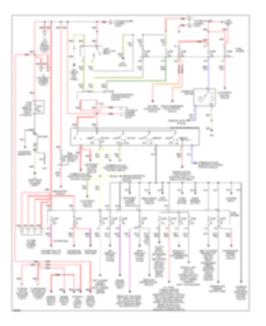
Power Distribution Wiring Diagram, Convertible (1 of 2) for Audi RS 4 2008
List of elements for Power Distribution Wiring Diagram, Convertible (1 of 2) for Audi RS 4 2008:
- 10a
- 11a
- 16a
- 18a
- 22a
- 30a
- 31a
- 33a
- 36a
- 37a
- 43a
- Abs
- Abs control module
- Acc
- Air quality sensor & high pressure sensor
- Backup light switch, data link connector (dlc), automatic day/ night interior mirror & shift lock solenoid
- Battery
- Button
- Cigarette lighter
- Climatronic control module
- Clutch pedal switch, esp sensor unit, abs control module, anti-slip control switch & brake pedal switch
- Control module fuse 1
- Convertible
- Convertible top control module
- Driver's door control module
- Engine control module (ecm)
- Engine control module (ecm) & starter lock/clutch pedal switch relay
- Engine control module (ecm) 2
- Front passenger's door control module
- Fuse 10a
- Fuse 150a
- Fuse 15a
- Fuse 20a
- Fuse 30a
- Fuse 40a
- Fuse 5a
- Fuse holder
- Fuse strip (rear of engine compt, in plenum)
- G11 (right rear of engine compt)
- G33
- G44 (above left kick panel)
- G701
- Garage door opener control head
- Garage door opener control module
- Headlight adjuster, left headlight beam adjusting motor & right headlight beam adjusting motor
- Headlight range control module
- Ignition/starter switch
- Instrument cluster control module
- Interior lights system
- Left headlight power output stage
- Left washer nozzle heater & right washer nozzle heater
- Light switch
- Load reduction relay
- Lock
- Nca
- Oil level thermal sensor, navigation w/ cd mechanism control module, left & right rear heated seat control module, board computer function selector switch 2, parking aid control module & tiptronic switch
- Red
- Right headlight power output stage
- Seat occupied recognition control module, front passenger's airbag disabled indicator lamp & air bag control module
- Servotronic control module
- Sport program
- Start
- Start system
- Starter & generator
- Starter relay
- Steering column electronic systems control module
- T10b
- T32b
- Telephone amplifier
- Telephone transceiver
- To 4-pin relay carrier (diagram 2 of 2)
- To brake vacuum pump fuse (diagram 2 of 2)
- To fuse holder (diagram 2 of 2)
- To secondary air injection pump fuse (diagram 2 of 2)
- Trans- mission control module (tcm)
- Vehicle electrical system control module
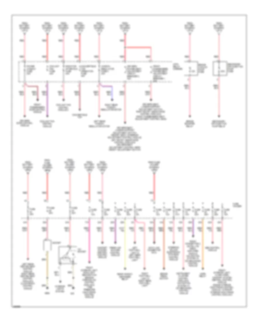
Power Distribution Wiring Diagram, Convertible (2 of 2) for Audi RS 4 2008
List of elements for Power Distribution Wiring Diagram, Convertible (2 of 2) for Audi RS 4 2008:
- 12a
- 12v socket
- 13a
- 14a
- 15a
- 17a
- 24a
- 25a
- 26a
- 34a
- 35a
- 38a
- 39a
- 4-pin relay carrier
- 40a
- 42a
- 44a
- 50a
- Abs control module
- Brake booster relay
- Brake pedal switch
- Brake vacuum pump fuse
- Comfort system central control module
- Convertible top
- Convertible top operation fuse 40a
- Coolant fan control module
- Coolant fan control module 2
- Coolant fan fuse 40a
- Data link connector (dlc)
- Driver's door control module
- Driver's power seat adjustment circuit breaker 2 30a
- Driver's seat lumbar support adjustment switch, memory seat/ steering adjustment control module, left entry assistance control module & driver's seat adjustment control head height adjustment switch
- Driver's seat lumbar support adjustment switch, right entry assistance control module & front passenger's seat adjustment control head
- Fresh air blower control module
- From battery (diagram 1 of 2)
- From battery holder (diagram 1 of 2)
- From fuse holder (diagram 1 of 2)
- Front interior light, alarm horn, comfort system central control module, radar interior monitoring control module 1 & radar interior monitoring control module 2
- Front interior light, rain/light recognition sensor, parking aid control module & tire pressure monitoring control module
- Front passenger's door control module
- Front passenger's power seat adjustment circuit breaker 1 30a
- Fuse 10a
- Fuse 15a
- Fuse 20a
- Fuse 25a
- Fuse 30a
- Fuse 35a
- Fuse 5a
- Fuse holder
- G33
- G663
- Horn relay
- Instrument cluster control module & navigation system w/ cd mechanism control module
- Interior lights system
- Left footwell light & left rear footwell light
- Left rear heated seat control module, right rear heated seat control module & climatronic control module
- Left rear window regulator motor
- Power window fuse 30a
- Radiator after run fuse 40a
- Radio connector 3, satellite radio, amplifier, radio & navigation system w/ cd mechanism control module
- Rear window defogger relay
- Red
- Right footwell light & right rear footwell light
- Right rear window regulator motor
- Secondary air injection pump fuse
- Secondary air injection pump relay
- Socket
- Steering column electronic systems control module
- Window regulator fuse 2 30a
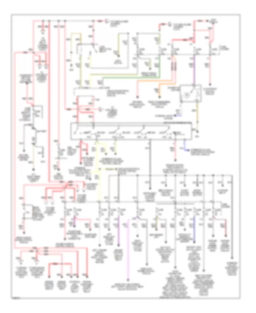
Power Distribution Wiring Diagram, Except Convertible (1 of 2) for Audi RS 4 2008
List of elements for Power Distribution Wiring Diagram, Except Convertible (1 of 2) for Audi RS 4 2008:
- 10a
- 11a
- 16a
- 18-pin connector, oil level thermal sensor, rear window shade switch, left rear heated seat control module, right rear heated seat control module, parking aid control module & tiptronic switch
- 18a
- 22a
- 30a
- 31a
- 33a
- 36a
- 37a
- 4-pin relay
- 43a
- Abs control module
- Abs control module fuse 1
- Acc
- Air quality sensor & high pressure sensor
- Anti-slip control switch, abs control module & brake pedal switch
- Backup light switch, shift lock solenoid, data link connector (dlc) & automatic day/night interior mirror
- Batter interrupt igniter
- Battery
- Carrier (diagram 2 of 2)
- Cigarette lighter
- Climatronic control module
- Driver's door control module
- Engine control module (ecm)
- Engine control module (ecm) & ecm 2
- Engine control module (ecm) & starter lock/clutch pedal switch relay
- Engine control module (ecm) 2
- Esp sensor unit
- Front passenger's door control module
- Fuse 10a
- Fuse 150a
- Fuse 15a
- Fuse 20a
- Fuse 30a
- Fuse 40a
- Fuse 5a
- Fuse holder
- Fuse strip (rear of engine compt, in plenum)
- G11 (right rear of engine compt)
- G33
- G49
- G701
- Garage door opener control head
- Garage door opener control module
- Headlight adjuster & left & right headlight beam adjusting motor
- Headlight range control module
- Ignition/starter switch
- Instrument cluster control module
- Interior lights system
- Left headlight power output stage
- Left washer nozzle heater & right washer nozzle heater
- Light switch
- Load reduction relay
- Lock
- Nca
- Power sunroof control module
- Rear shade circuit breaker (left side of dash)
- Rear window shade control module
- Rear window wiper motor
- Red
- Right headlight power output stage
- Seat occupied recognition control module, front passenger's airbag disabled indicator lamp & air bag control module
- Servotronic control module
- Sport program button
- Start
- Start system button
- Starter relay
- Steering column electronic systems control module
- T10b
- T32b
- Telephone amplifier
- Telephone transceiver & 18-pin connector
- To 4-pin relay carrier (diagram 2 of 2)
- To brake vacuum pump fuse (diagram 2 of 2)
- To fuse holder (diagram 2 of 2)
- To secondary air injection pump fuse (diagram 2 of 2)
- Vehicle electrical system control module
- Windshield heating voltage converter
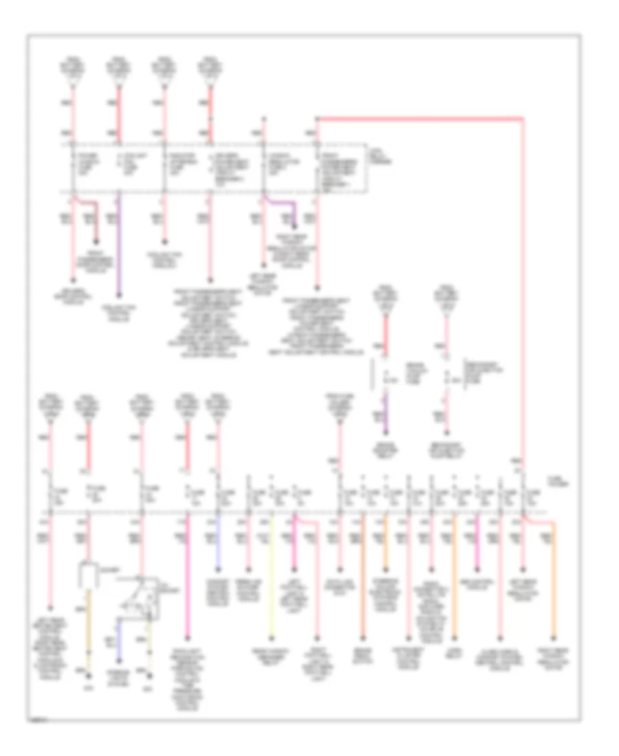
Power Distribution Wiring Diagram, Except Convertible (2 of 2) for Audi RS 4 2008
List of elements for Power Distribution Wiring Diagram, Except Convertible (2 of 2) for Audi RS 4 2008:
- 12a
- 12v socket
- 13a
- 14a
- 15a
- 17a
- 23a
- 24a
- 25a
- 26a
- 34a
- 35a
- 38a
- 39a
- 4-pin relay carrier
- 40a
- 42a
- 44a
- 50a
- Abs control module
- Alarm horn & comfort system central control module
- Brake booster relay
- Brake pedal switch
- Brake vacuum pump fuse
- Comfort system central control module
- Coolant fan control module
- Coolant fan control module 2
- Coolant fan fuse 40a
- Data link connector (dlc)
- Driver's door control module
- Driver's power seat adjustment circuit breaker 2 10a
- Fresh air blower control module
- From battery (diagram 1 of 2)
- From fuse holder (diagram 1 of 2)
- Front passenger's door control module
- Front passenger's power seat adjustment circuit breaker 1 10a
- Front passenger's seat adjustment switch, front passenger's seat lumbar support adjustment switch, driver's seat lumbar support adjustment switch, memory seat/ steering adjustment control module, & driver's seat adjustment module
- Front passenger's seat lumbar support adjustment switch, front passenger's power seat control module, & front passenger's seat adjustment switch front passenger's seat adjustment control module
- Fuse 10a
- Fuse 15a
- Fuse 20a
- Fuse 25a
- Fuse 30a
- Fuse 35a
- Fuse 5a
- Fuse holder
- G33
- G78
- Horn relay
- Instrument cluster control module
- Interior lights system
- Left footwell light & left rear footwell light
- Left rear heated seat control module, right rear heated seat control module & climatronic control module
- Left rear window regulator motor
- Power window fuse 30a
- Radiator after-run fuse 40a
- Radio connector 3 satellite radio, amplifier, radio & navigation system w/ cd drive control module
- Rain/light recognition sensor, parking aid control module & tire pressure monitoring control module
- Rear window defogger relay
- Red
- Right footwell light & right rear footwell light
- Right rear window regulator motor
- Right rear window regulator motor & right rear door control module
- Secondary air injection pump fuse
- Secondary air injection pump relay
- Socket
- Steering column electronic systems control module
- Window regulator fuse 2 30a

 Čeština
 Dansk
Dansk Deutsch
 Ελληνικά
 English
 English
 Español
 Suomi
Suomi Français
 עברית
עברית Hrvatski
 Magyar
 Italiano
 日本語
日本語 한국어
한국어 Nederlands
 Polski
 Português
 Português
 Română
 Русский
 Slovenčina
 Slovenščina
 Svenska
 Türkçe
 中文 (中国)