TRANSMISSION
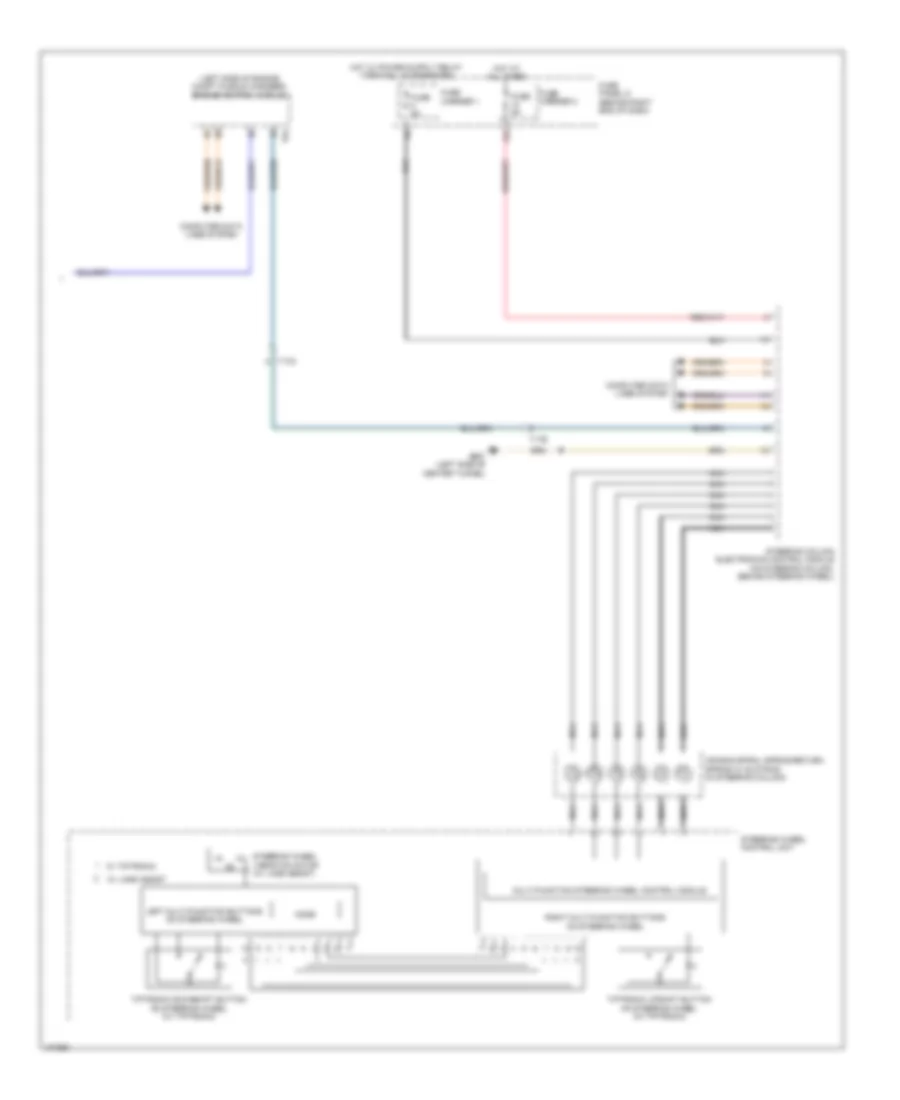
A/T Wiring Diagram, 8 Speed A/T (1 of 2) for Audi A4 Premium Plus 2013


List of elements for A/T Wiring Diagram, 8 Speed A/T (1 of 2) for Audi A4 Premium Plus 2013:
- 10a
- 12a
- Automatic transmission pressure regulating valve 1
- Automatic transmission pressure regulating valve 2
- Automatic transmission pressure regulating valve 3
- Automatic transmission pressure regulating valve 4
- Automatic transmission pressure regulating valve 5
- Automatic transmission pressure regulating valve 6
- Automatic transmission pressure regulating valve 7
- Comfort system central control module (right side of trunk)
- Computer data lines system
- Drive position sensor
- Fuse 15a
- Fuse 5a
- Fuse carrier 1
- Fuse panel c (behind left end of dash)
- G12 (left rear of engine compt)
- G688 (right side of center tunnel)
- Hot at all times
- Power distribution system
- Relay/ fuse panel b (in plenum chamber electronics box)
- Selector lever sensor system control module (on shifter unit)
- Solenoid valve 1
- T17q
- T32b
- T32d
- Transmission control module (tcm) (in mechatronic unit)
- Transmission fluid temperature sensor
- Transmission input speed sensor
- Transmission output speed sensor
- Transmission park selector switch & shift lock solenoid (shift lock solenoid: on shifter unit)
- Vehicle electrical system control module (under left side of dash)
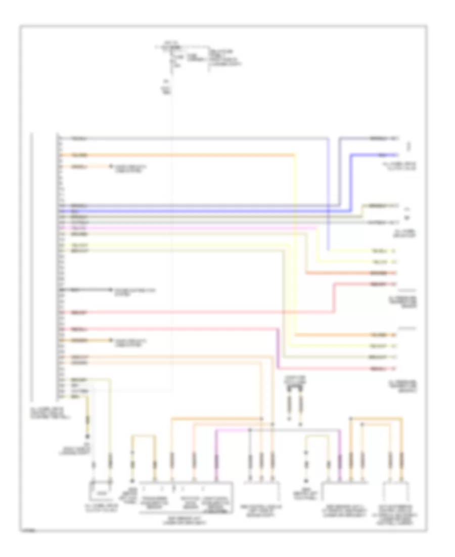
A/T Wiring Diagram, 8 Speed A/T (2 of 2) for Audi A4 Premium Plus 2013
List of elements for A/T Wiring Diagram, 8 Speed A/T (2 of 2) for Audi A4 Premium Plus 2013:
- (left side of engine compt plenum chamber) engine control module
- 12a
- Air bag spiral spring/return spring w/ slip ring (in steering column)
- Computer data lines system
- Fuse 5a
- Fuse carrier 1
- Fuse carrier 2
- Fuse panel d (behind right end of dash)
- G687 (left side of center tunnel)
- Hot at all times
- Left multi-function buttons on steering wheel
- Mode
- Multi-function steering wheel control module
- Nca
- Right multi-function buttons on steering wheel
- Steering column electronics control module (on steering column, behind steering wheel)
- Steering wheel control unit
- Steering wheel vibration motor (w/ lane assist)
- T17b
- T17q
- T94
- Tiptronic downshift button on steering wheel (w/ tiptronic)
- Tiptronic upshift button on steering wheel (w/ tiptronic)
- W/ lane assist
- W/ tiptronic
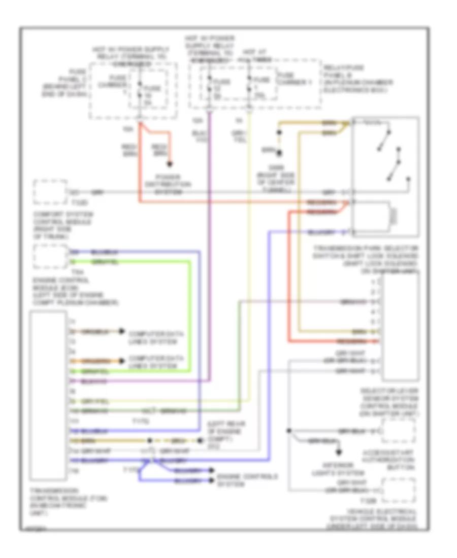
A/T Wiring Diagram, CVT for Audi A4 Premium Plus 2013
List of elements for A/T Wiring Diagram, CVT for Audi A4 Premium Plus 2013:
- (left rear of engine compt) g12
- 10a
- 12a
- Access/start authorization button
- Comfort system control module (right side of trunk)
- Computer data lines system
- Engine control module (ecm) (left side of engine compt plenum chamber)
- Engine controls system
- Fuse 15a
- Fuse 5a
- Fuse carrier
- Fuse carrier 1
- Fuse panel c (behind left end of dash)
- G688 (right side of center tunnel)
- Hot at all times
- Interior lights system
- Power distribution system
- Relay/fuse panel b (in plenum chamber electronics box)
- Selector lever sensor system control module (on shifter unit)
- T17q
- T32b
- T32d
- T94
- Transmission control module (tcm) (in mechatronic unit)
- Transmission park selector switch & shift lock solenoid (shift lock solenoid: on shifter unit)
- Vehicle electrical system control module (under left side of dash)
AWD Wiring Diagram for Audi A4 Premium Plus 2013
List of elements for AWD Wiring Diagram for Audi A4 Premium Plus 2013:
- Abs control module (left side of engine compt)
- Active steering control module (w/ special equipment) (under driver's footwell carpet)
- All wheel drive clutch valve
- All wheel drive clutch valve 2
- All wheel drive control module (in spare tire well)
- All wheel drive pump
- Computer data lines system
- Esp sensor unit (under driver's seat)
- Esp sensor unit 2 (w/ special equipment) (under driver's seat)
- Fuse 35a
- Fuse carrier 2
- G51 (right side of luggage compt)
- G639 (behind left kick panel)
- Hot at all times
- Longitudinal acceleration sensor (if equipped)
- Oil pressure/ temperature sensor
- Oil pressure/ temperature sensor 2
- Power distribution system
- Relay/fuse panel f (right side of luggage compt)
- Rotation rate sensor
- Transverse acceleration sensor

 Čeština
 Dansk
Dansk Deutsch
 Ελληνικά
 English
 English
 Español
 Suomi
Suomi Français
 עברית
עברית Hrvatski
 Magyar
 Italiano
 日本語
日本語 한국어
한국어 Nederlands
 Polski
 Português
 Português
 Română
 Русский
 Slovenčina
 Slovenščina
 Svenska
 Türkçe
 中文 (中国)