WARNING SYSTEMS
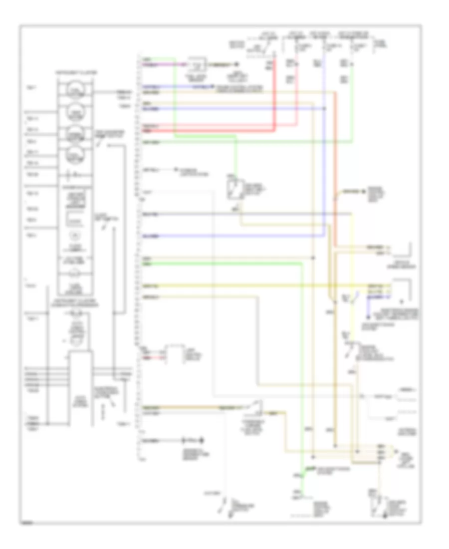
Warning Systems Wiring Diagram for Audi A6 1997
List of elements for Warning Systems Wiring Diagram for Audi A6 1997:
- (6 bulbs)
- 86s
- Air conditioning system
- Antenna amplifier
- Auto check system
- Auto- check control lights
- C10
- Center console light booster
- Clock
- Clock light
- Clock set button
- Cruise control system (vehicle speed output)
- Dimmer switch
- Driver's door contact switch
- Driver's seat belt switch
- Electronic engine coolant temperature (ect) thermal switch
- Electronic voice check button
- Engine control module (ecm)
- Engine coolant level (elc) warning switch
- Engine oil
- Fluid level
- Fuel gauge
- Fuel level sensor
- Fuse 15 5a
- Fuse 7 5a
- Fuse 8 15a
- Fuse panel
- G404 (near left taillight)
- G900 (lower left "a"pillar)
- Hot at all times
- Hot in run or acc
- Hot w/ park or headlights on
- Ignition switch
- Illum. lights
- Instrument cluster
- Instrument cluster combination processor
- Interior lights system
- Key switch
- Lamp control module
- Oil pressure switch
- Radio
- Red
- Sensor
- Speed- ometer
- Switch
- T14
- T14-1
- T14-11
- T14-12
- T14-2
- T14-8
- T26
- T26-10
- T26-11
- T26-14
- T26-15
- T26-17
- T26-18
- T26-2
- T26-22
- T26-26
- T26-3
- T26-7
- T26-8
- T26a
- T26a-11
- T26a-12
- T26a-16
- T26a-3
- T26a-6
- T26a-7
- T26a-9
- T4m
- T4m-2
- T8/5
- Tach- ometer
- Temp gauge
- Temperature
- Trip odometer reset switch
- Vehicle speed sensor
- Voltage stabilizer
- Washer
- Windshield
 Čeština
 Dansk
Dansk Deutsch
 Ελληνικά
 English
 English
 Español
 Suomi
Suomi Français
 עברית
עברית Hrvatski
 Magyar
 Italiano
 日本語
日本語 한국어
한국어 Nederlands
 Polski
 Português
 Português
 Română
 Русский
 Slovenčina
 Slovenščina
 Svenska
 Türkçe
 中文 (中国)
 Français