AUTOMOTIVE ELECTRICIANS PORTAL

WARNING SYSTEMS – Lexus GS 350 2014 – SYSTEM WIRING DIAGRAMS

WARNING SYSTEMS

Seat Belt Warning Wiring Diagram for Lexus GS 350 2014

Seat Belt Warning Wiring Diagram for Lexus GS 350 2014 https://portal-diagnostov.com/license.html
https://portal-diagnostov.com/license.html Automotive Electricians Portal FZCO Automotive Electricians Portal FZCO
Download PDF file

List of elements for Seat Belt Warning Wiring Diagram for Lexus GS 350 2014:

  • (behind right end of dash) right cowl side j/b
  • (inboard side of left front seat) left front seat inner belt
  • 5v ic
  • 5v+b
  • A50
  • Air bag fuse 10a
  • Air bag sensor assembly (under rear of center floor console)
  • Altb
  • Auto
  • Becu
  • Buckle switch
  • C17
  • C44
  • C47
  • Can i/f
  • Canh
  • Canl
  • Combination meter assembly
  • Computer data lines system
  • Cpu
  • D32
  • Engine room r/b 1 (right rear of engine compt)
  • Engine room r/b 2 (left side of engine compt)
  • Flcy
  • Fsr+
  • Fsr-
  • Gauge fuse 5a
  • Gnd
  • Gnd1
  • Head
  • Headlight dimmer switch assembly
  • Hot at all times
  • Hot w/ ig2 relay energized
  • Hot w/ lh-ig1 1 relay energized
  • I/f
  • Ig+
  • Ig2
  • Lbe+
  • Lbe-
  • Led driver
  • Left cowl side j/b (behind left end of dash)
  • Left front door courtesy light switch (in left front "b" pillar)
  • Left rear outer weight detection sensor
  • Lh j/b-b fuse 7.5a
  • Lh-ig fuse 10a
  • Light control switch
  • Main body ecu
  • Mpx-b fuse 10a
  • N1 (left kick panel)
  • N12
  • N3 (under center console)
  • N40
  • N52
  • N6 (left side of dash)
  • N7 (right kick panel)
  • Na1
  • Na2
  • Nn1
  • Nt1
  • Occupant detection ecu (under front passenger's seat)
  • Ods fuse 5a
  • Off
  • Pnk
  • Red
  • Right cowl side j/b (behind right end of dash)
  • Right front seat inner belt assembly (inboard side of right front seat)
  • Right rear outer weight detection sensor
  • Speaker
  • T12
  • Tail
  • Telltales
  • U12
  • Z12
  • Z13

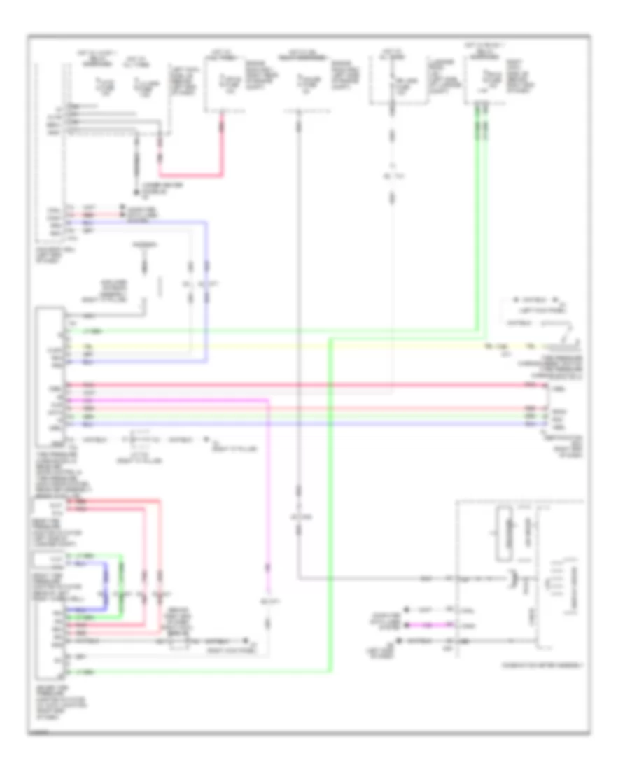
Tire Pressure Monitoring Wiring Diagram for Lexus GS 350 2014

Tire Pressure Monitoring Wiring Diagram for Lexus GS 350 2014 https://portal-diagnostov.com/license.html
https://portal-diagnostov.com/license.html Automotive Electricians Portal FZCO Automotive Electricians Portal FZCO
Obtenez l'accès à tous les schémas de câblage de la voitureDownload PDF file

List of elements for Tire Pressure Monitoring Wiring Diagram for Lexus GS 350 2014:

  • (behind right end of dash) right cowl side j/b
  • (under center console) n3
  • 5v ic
  • 5v+b
  • A21
  • A38
  • Alsi
  • Altb
  • Amplifier antenna assembly (right "c" pillar)
  • Antenna
  • Asel
  • Becu
  • C39
  • Can i/f
  • Canh
  • Canl
  • Certification ecu (right end of dash)
  • Clsw
  • Combination meter assembly
  • Computer data lines system
  • Cpu
  • Csel
  • D32
  • Data
  • Display driver
  • Driver tire pressure monitor initiator (w/ auto location) (right end of dash)
  • Engine room r/b 1 (right rear of engine compt)
  • Engine room r/b 2 (left side of engine compt)
  • F in
  • F ot
  • Fr+
  • Fr-
  • Front tire pressure monitor initiator (rear of left front wheelwell)
  • Gauge fuse 5a
  • Gnd
  • Gnd1
  • Hot at all times
  • Hot w/ ig2 relay energized
  • Hot w/ lh-ig1 1 relay energized
  • Hot w/ rh-ig1 1 relay energized
  • Ig+
  • J/c t44 (right "c" pillar)
  • Led driver
  • Left cowl side j/b (behind left end of dash)
  • Lh j/b-b fuse 7.5a
  • Lh-ig fuse 10a
  • Luggage room j/b 1 (left side of luggage compt)
  • Main body ecu (left end of dash)
  • Mpx-b fuse 10a
  • N1 (left kick panel)
  • N12
  • N40
  • N6 (left side of dash)
  • N7 (right kick panel)
  • Na2
  • Nca
  • Nt1
  • Nu1 red
  • Pnk
  • Prg
  • R in
  • R ot
  • Rco
  • Rda
  • Rdam
  • Rear tire pressure monitor initiator (left side of luggage compt)
  • Red
  • Rh-ig fuse 10a
  • Right cowl side j/b (behind right end of dash)
  • Rr j/b-b fuse 10a
  • Rr+
  • Rr-
  • Sil
  • T2 (right "c" pillar)
  • T32
  • T51
  • Telltales
  • Tire pressure warning ecu & receiver (door control & tire pressure monitoring system receiver assembly) (right "c" pillar)
  • Tire pressure warning reset switch (tire pressure warning switch 1)
  • Tu1