ENGINE PERFORMANCE
4.2L
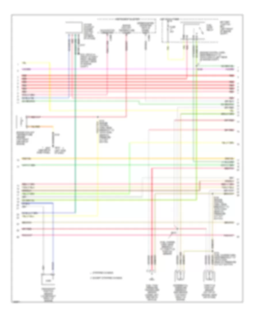
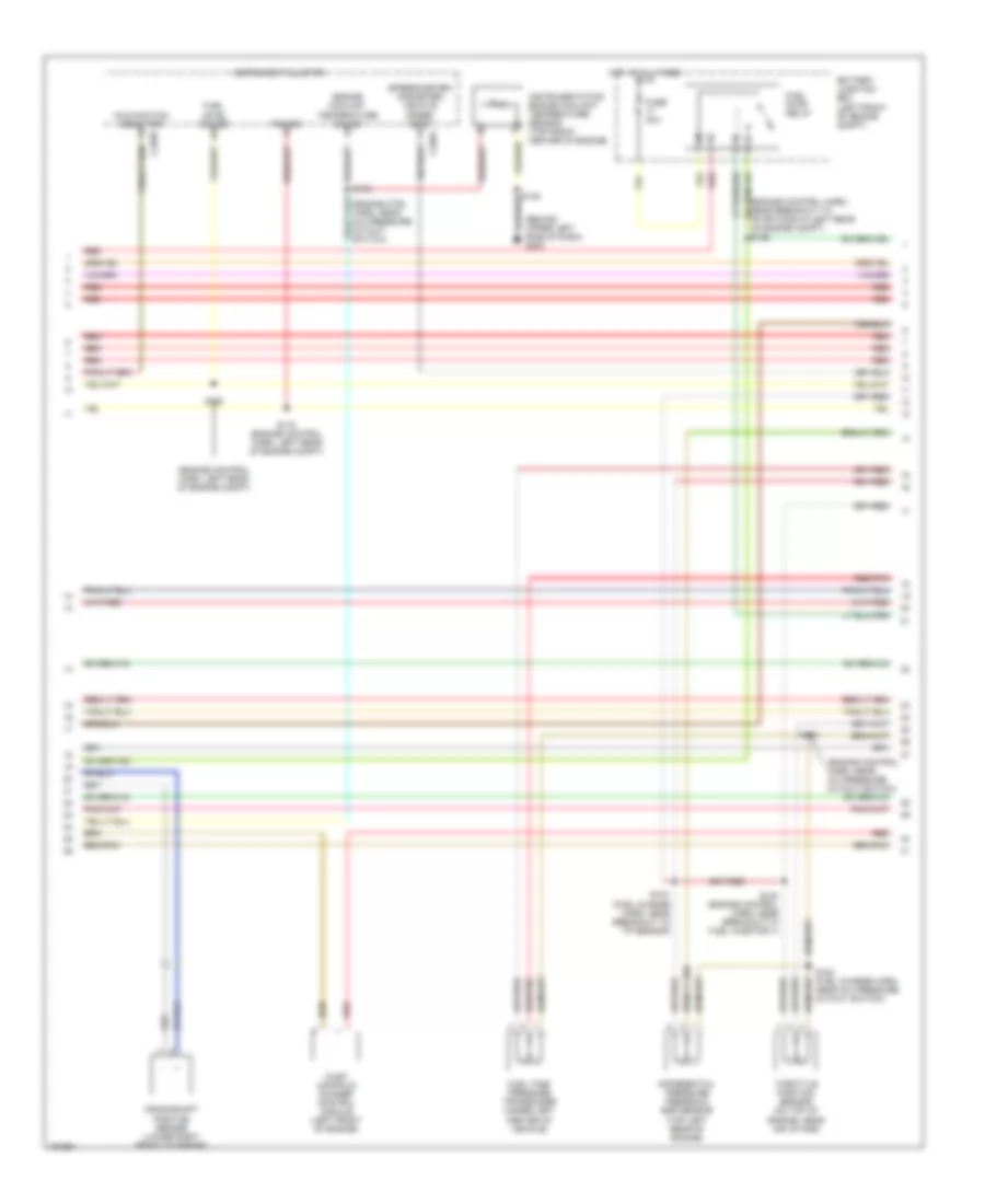
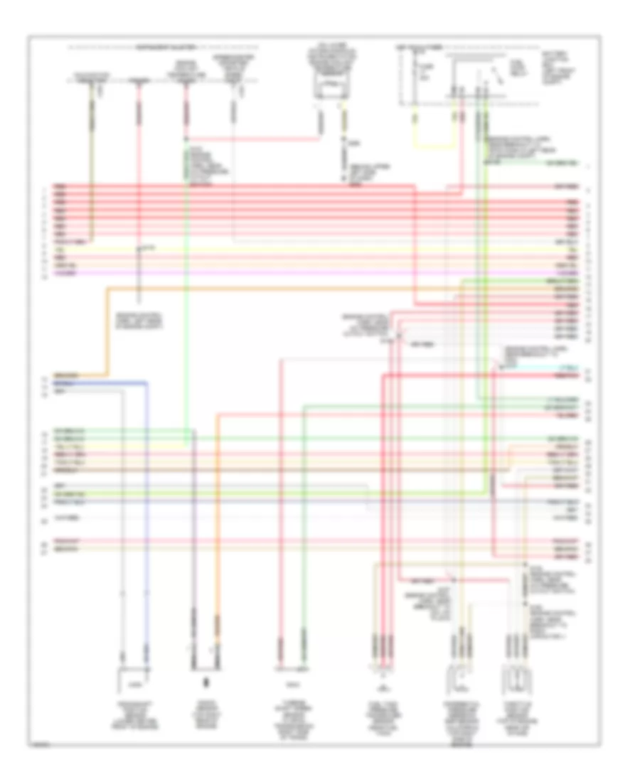
4.2L, Engine Performance Wiring Diagrams (1 of 4) for Ford Econoline E350 Super Duty 2002


List of elements for 4.2L, Engine Performance Wiring Diagrams (1 of 4) for Ford Econoline E350 Super Duty 2002:
- (ends in harness)
- (front of left front fender)
- (front of right front fender)
- A/c on sig
- Air conditioning system
- Battery junction box (left front of engine compt)
- Central junction box (below left side of dash, near left kick panel)
- Ckp sensor (+)
- Ckp sensor (-)
- Cylinder head temperature sensor (left rear of engine compt, on heater outlet elbow)
- Data link connector (partial) (left side of dash)
- Digital transmission range sensor (dtr sensor) (left side of transmission)
- Dtr-tr1
- Dtr-tr2
- Dtr-tr4
- Egr sol ctrl
- F gauge sender
- Fuel pump out
- Fuse 10a
- Fuse 30a
- Fuse 5a
- G100
- G101
- G101 (front of right front fender)
- Ground
- Ho2s 12 input
- Hot at all times
- Hot in run or start
- Iat input
- Ign coil
- Ign coil 1
- Ignition coil (left front of engine)
- Imrc
- Imrc monitor
- Instrument cluster system
- Ks -
- Maf rtn
- Mil ctrl
- Nca
- Not used
- O/d off
- Od cancel sw
- Overdrive cancel switch
- Pcm power diode
- Pcm power relay
- Powertrain control module (left rear of engine compt, near brake master cylinder)
- Prgrm signal
- R n
- Radio capacitor (attached to ignition coil)
- Red
- S110
- S127
- S140
- S142 (eng ctrl harn, near breakout to maf sensor)
- S169
- S175
- Scp bus (+)
- Scp bus (-)
- Shift sol b
- Spark plugs
- Tcil
- Tfts input
- To dtr sensor (diagram 4 of 4)
- Transmission control indicator lamp
- Water temp sens
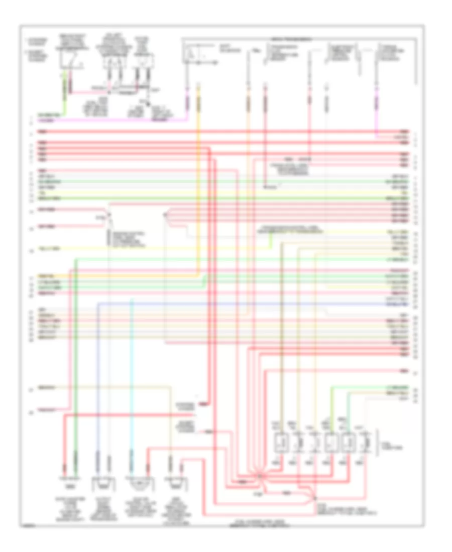
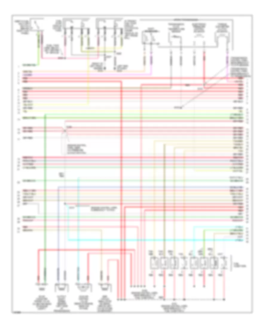
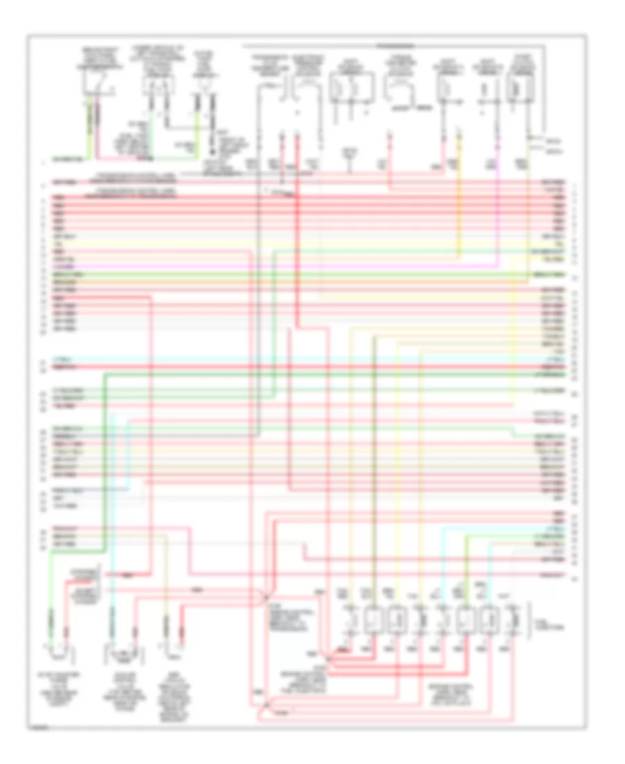
4.2L, Engine Performance Wiring Diagrams (2 of 4) for Ford Econoline E350 Super Duty 2002
List of elements for 4.2L, Engine Performance Wiring Diagrams (2 of 4) for Ford Econoline E350 Super Duty 2002:
- (engine control harn, near breakout to 76-pin conn in left rear of engine compt)
- (fuel charge harn, near breakout to throttle position sensor)
- (left side of dash)
- (speedometer/ odometer) vehicle speed input
- Battery junction box (left front of engine compt)
- C220a
- C220b
- Crankshaft position sensor (lower right front of engine)
- Differential pressure feedback egr sensor (top right front of engine)
- Engine coolant temperature gauge
- Engine coolant temperature sender (top front center of engine)
- Except stripped chassis
- Fuel pump relay
- Fuel tank pressure transducer sensor (under left center of vehicle)
- Fuse 30a
- G101 (or g114) (front of right front fender or right rear of engine compt)
- G203
- G207 (center of dash panel)
- Hot at all times
- Instrument cluster
- Intake manifold runner control module (on rear of intake)
- Malfunction indicator
- Red
- Red/pnk
- S103
- S107
- S126
- S133 (engine control harn, near breakout to 16-pin conn near a/c pressure cut out switch)
- S138 (engine control harn, near breakout to 16-pin conn near a/c pressure cut out switch)
- Stripped chassis
- Throttle position sensor (on top of engine, near air intake)
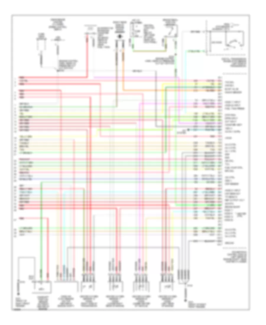
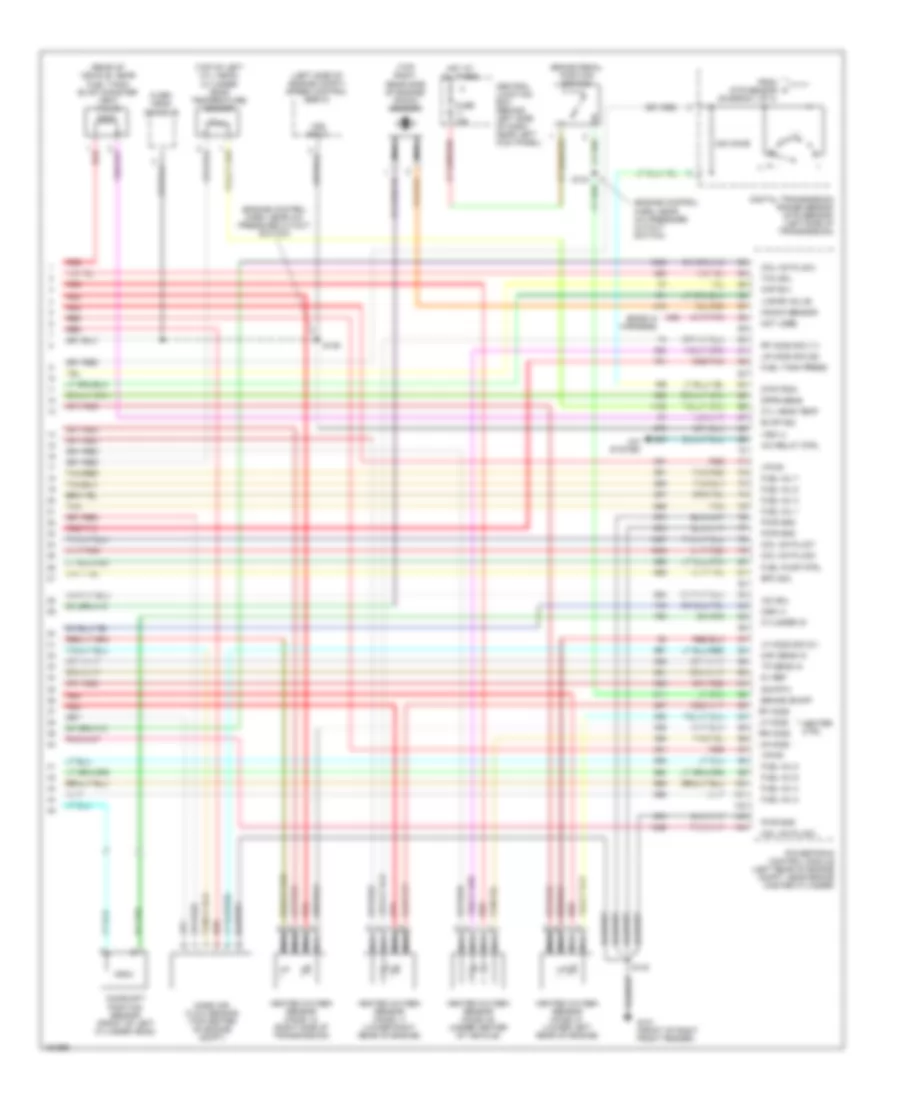
4.2L, Engine Performance Wiring Diagrams (3 of 4) for Ford Econoline E350 Super Duty 2002
List of elements for 4.2L, Engine Performance Wiring Diagrams (3 of 4) for Ford Econoline E350 Super Duty 2002:
- (behind right kick panel) inertia fuel shut-off switch
- (engine control harn, near a/c pressure cut out switch)
- (fuel charge harn, near breakout to fuel injector 2)
- (in center rear of engine compt)
- (in fuel tank) fuel pump module
- (on left frame rail) (cutaways/ stripped chassis) in transit fuel pump module
- (trans cntrl harn, near breakout to dtr sensor)
- (transmission control harn, near breakout to transmission)
- 4r70w transmission
- Chassis
- Egr vacuum regulator solenoid (above center of right valve cover)
- Electronic pressure control solenoid
- Evap canister purge valve
- Except stripped chassis
- Fuel injectors
- G100 (front of left front fender)
- G207 (center of dash)
- Idle air control valve (right side of engine, near ignition coil)
- Nca
- Output shaft speed sensor (left side of transmission)
- Red
- Red/pnk
- S100
- S102
- S105 (fuel charge harn, near breakout to fuel injector 3)
- S106
- S136
- S307
- S309 (fuel tank harn, below left center of vehicle)
- Shift solenoids
- Stripped
- Stripped chassis
- Tan
- Torque converter clutch solenoid
- Transmission fluid temperature sensor
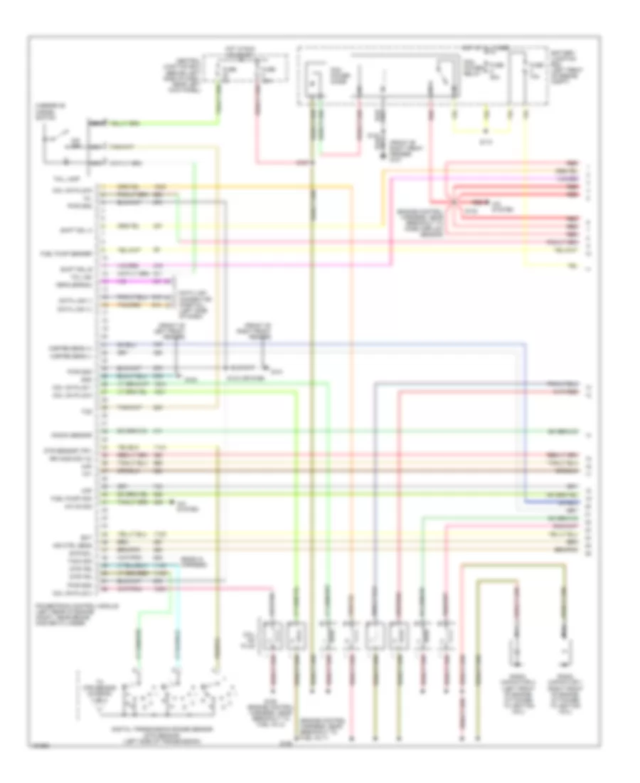
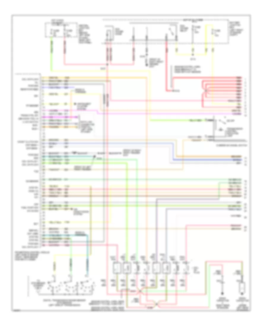
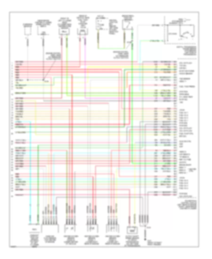
4.2L, Engine Performance Wiring Diagrams (4 of 4) for Ford Econoline E350 Super Duty 2002
List of elements for 4.2L, Engine Performance Wiring Diagrams (4 of 4) for Ford Econoline E350 Super Duty 2002:
- (engine control harn, near a/c pressure cut out switch) s135
- (near brake master cylinder) speed control servo
- (right rear side of engine) knock sensor
- 240 ohms
- A/c rly cntrl
- A/c system
- Brake on/off
- Brake pedal position switch
- Camshaft position sensor (on front center of engine)
- Canister vent
- Central junction box (below left side of dash, near left kick panel)
- Cht input
- Cmp sensor
- Digital transmission range (dtr) sensor (left side of transmission)
- Dpfe input
- Dtr-tr3a
- Epc sol
- Evap valve
- Evaporative emissions canister vent solenoid (rear of vehicle, near fuel tank)
- From dtr sensor (diagram 1 of 4)
- Fuel pump ctrl
- Fuel tank press
- Fuse 15a
- G101 (front of right front fender)
- Gnd
- Ground
- Heated oxygen sensor 11 (ho2s) (lower right rear of engine)
- Heated oxygen sensor 12 (ho2s) (right side of transmission)
- Heated oxygen sensor 21 (ho2s) (left rear of engine)
- Heated oxygen sensor 22 (ho2s) (under center of vehicle)
- Heater ctrl
- Ho2s 11
- Ho2s 11 input
- Ho2s 12
- Ho2s 21
- Ho2s 21 input
- Ho2s 22
- Ho2s 22 input
- Hot at all times
- Iac ctrl
- Ign coil
- Inj 1 ctrl
- Inj 2 ctrl
- Inj 3 ctrl
- Inj 4 ctrl
- Inj 5 ctrl
- Inj 6 ctrl
- Kap b(+)
- Knock sensor
- Maf sens out
- Mass air flow sensor (on top center of engine compt)
- Nca
- Oss (-)
- Over- head console
- Powertrain control module (left rear of engine compt, near master cylinder)
- Red
- Red/pnk
- Ref output volt
- S134 (engine control harn, near a/c pressure cut out switch)
- S140
- Sig rtn
- Tan
- Tcc sol
- Tcil
- Tp sens in
- Vpwr
- Vss (+)
- Vss input
4.6L
4.6L, Engine Performance Wiring Diagrams (1 of 4) for Ford Econoline E350 Super Duty 2002
List of elements for 4.6L, Engine Performance Wiring Diagrams (1 of 4) for Ford Econoline E350 Super Duty 2002:
- (ends in harness)
- (engine control harness, near breakout to fuel inj 7)
- (engine control harness, near breakout to mass airflow sensor)
- (front of left front fender)
- (front of right front fender)
- (front of right front fender) g101
- A/c on sig
- A/c system
- Air ctrl sens
- Battery junction box (left front of engine compt)
- Central junction box (behind left side of dash, near left kick panel)
- Coil on plug
- Coil on plug 1
- Coil on plug 3
- Coil on plug 5
- Coil on plug 6
- Data link (+)
- Data link (-)
- Data link connector (partial) (left side of dash)
- Digital transmission range sensor (dtr sensor) (left side of transmission)
- Dtr sensor (tr1)
- Dtr-tr2
- Dtr-tr4
- Ect
- Evr sol
- Feps (eprom)
- Fuel pump mon
- Fuel pump sender
- Fuse 10a
- Fuse 30a
- Fuse 5a
- G100
- G101
- Gnd
- Hot at all times
- Hot in run or start
- Knock sensor
- Maf
- Mil
- Misfire sens (+)
- Misfire sens (-)
- Nca
- O/d off
- Overdrive cancel switch
- Pcm power diode
- Pcm power relay
- Powertrain control module (left rear of engine compt, near brake master cylinder)
- Pwr gnd
- R n
- Radio capacitor 1 (right front of engine, attached to ignition coil)
- Radio capacitor 2 (left front of engine, attached to ignition coil)
- Red
- Rr ho2s sig (12)
- S110
- S127
- S140 (or s169)
- S142
- S150 (engine control harness, near breakout to fuel inj 2)
- S193
- Shift sol a
- Shift sol b
- Tach sig
- Tcil ind
- Tcil lamp
- Tcs
- Tft
- To dtr sensor (diagram 4 of 4)
4.6L, Engine Performance Wiring Diagrams (2 of 4) for Ford Econoline E350 Super Duty 2002
List of elements for 4.6L, Engine Performance Wiring Diagrams (2 of 4) for Ford Econoline E350 Super Duty 2002:
- (behind upper left side of dash) g203
- (engine control harn, left rear of engine compt)
- (engine control harn, near a/c pressure cutout switch)
- (engine control harn, near breakout to 76-pin conn in left rear of engine compt) s126
- (speedometer/ odometer) vehicle speed input
- Battery junction box (left front of engine compt)
- Crankshaft position sensor (lower right front of engine)
- Differential pressure feedback egr sensor (top left rear of engine)
- Engine coolant temperature gauge
- Fuel level gauge
- Fuel pump relay
- Fuel tank pressure transducer (under left center of vehicle)
- Fuse 30a
- Hot at all times
- Inlet manifold runner control module (left front of engine)
- Instrument cluster
- Instrumentation engine coolant temperature sensor (top front center of engine)
- Malfunction indicator
- Power
- Red
- Red/pnk
- S103 (fuel charge harn, near breakout to tp sensor)
- S120
- S133
- S138
- S153 (fuel charge harn, near a/c pressure cutout switch)
- S154 (engine control harn, near breakout to fuel injector 7)
- S175 (engine control harn, left rear of engine compt)
- Throttle position sensor (on top of engine, near air intake)
4.6L, Engine Performance Wiring Diagrams (3 of 4) for Ford Econoline E350 Super Duty 2002
List of elements for 4.6L, Engine Performance Wiring Diagrams (3 of 4) for Ford Econoline E350 Super Duty 2002:
- (engine control harn, in breakout to pcm)
- (engine control harn, near a/c pressure cutout switch)
- (front of left front fender) g100
- (fuel tank harn, below left center of vehicle)
- (in center rear of engine compt)
- (left end of dash) g203
- (transmission control harn, near breakout to dtr sensor)
- (transmission control harn, near breakout to transmission)
- 4r70w transmission
- Egr vacuum regulator solenoid (above left valve cover, on bracket)
- Electronic pressure control solenoid
- Evap canister purge valve
- Fuel injectors
- Fuel pump module (in fuel tank)
- Idle air control valve (rear of engine, near air intake)
- In transit fuel pump module (cutaways) (under vehicle, on left frame rail)
- Inertia fuel shut-off switch (behind right kick panel)
- Nca
- Output shaft speed sensor (left side of transmission)
- Red
- Red/pnk
- S100
- S102
- S136
- S137
- S151 (engine control harn, near breakout to fuel injector 4)
- S152 (engine control harn, near breakout to fuel injector 8)
- S268
- S309
- S310
- Shift solenoids
- Tan
- Tan/ red
- Tan/red
- Torque converter clutch solenoid
- Transmission fluid temperature sensor
4.6L, Engine Performance Wiring Diagrams (4 of 4) for Ford Econoline E350 Super Duty 2002
List of elements for 4.6L, Engine Performance Wiring Diagrams (4 of 4) for Ford Econoline E350 Super Duty 2002:
- (ends in harness)
- (engine control harn, near a/c pressure cutout switch)
- (left side of engine compt) speed control servo
- (rear of vehicle, near fuel tank) evap canister vent valve
- (top of left cyl head) cylinder head temperature sensor
- (top right rear side of engine) knock sensor
- 240 ohms
- 5v ref
- A/c relay ctrl
- A/c system
- Brake on/off
- Brake pedal position switch
- Camshaft position sensor (front of left cylinder head)
- Central junction box (behind left side of dash, near left kick panel)
- Coil on plug 2
- Coil on plug 4
- Coil on plug 7
- Coil on plug 8
- Cyl head temp
- Cylinder id
- Digital transmission range sensor (dtr sensor) (left side of transmission)
- Dpfe sens
- Dtr-tr3a
- Epc sol
- Evap sol
- From dtr sensor (diagram 1 of 4)
- Fuel inj 1
- Fuel inj 2
- Fuel inj 3
- Fuel inj 4
- Fuel inj 5
- Fuel inj 6
- Fuel inj 7
- Fuel inj 8
- Fuel pump ctrl
- Fuel tank press
- Fuse 15a
- G101 (front of right front fender)
- Heated oxygen sensor (ho2s) 11 (lower right rear of engine)
- Heated oxygen sensor (ho2s) 12 (right side of transmission)
- Heated oxygen sensor (ho2s) 21 (lower left rear of engine)
- Heated oxygen sensor (ho2s) 22 (under center of vehicle)
- Heater ctrl
- Hot at all times
- Iac sol
- Kap b(+)
- Knock sensor
- Lf ho2s
- Lf ho2s sig (21)
- Lr ho2s
- Lr ho2s sig (22)
- Maf sens in
- Mass air- flow sensor (top center of engine compt)
- Nca
- Not used
- Oss (+)
- Over- head console
- Powertrain control module (left rear of engine compt, near brake master cylinder)
- Pwr gnd
- Red
- Red/pnk
- Rf ho2s
- Rf ho2s sig (11)
- Rr ho2s
- S135
- S140
- Sig rtn
- Tan
- Tan/red
- Tcc sol
- Tp sens in
- Vapor valve
- Vpwr
- Vss (+)
- Vss input
5.4L
5.4L, Engine Performance Wiring Diagrams (1 of 4) for Ford Econoline E350 Super Duty 2002
List of elements for 5.4L, Engine Performance Wiring Diagrams (1 of 4) for Ford Econoline E350 Super Duty 2002:
- (ends in harness)
- (engine control harn, near breakout to coil on plug 6)
- (engine control harn, near breakout to fuel injector 1)
- (engine control harn, near breakout to mass air flow sensor)
- (front of left front fender)
- (front of right front fender) g101
- 4 low switch
- A/c on sig
- Air conditioning system
- Battery junction box (left front of engine compt)
- Bus +
- Bus -
- Central junction box (behind left side of dash, near left kick panel)
- Ckp sens +
- Ckp sens -
- Coast clutch sw
- Coil on plug
- Coil on plug 1
- Coil on plug 3
- Coil on plug 5
- Coil on plug 6
- Data link connector (partial) (left side of dash)
- Digital transmission range sensor (dtr sensor) (left side of transmission)
- Dtr-tr1
- Dtr-tr2
- Dtr-tr4
- Ect
- Egr sol
- Fp sender
- Fuel pump mon
- Fuse 10a
- Fuse 30a
- Fuse 5a
- G100
- Gen scan tool in
- Gnd
- Ho2s (12)
- Hot at all times
- Hot in run or start
- Instrument cluster system
- Ks sensor
- Maf
- Mil
- Nca
- Not used
- O/d off
- Overdrive cancel switch
- Pcm power diode
- Pcm power relay
- Powertrain control module (left side of engine compt, near brake master cylinder)
- Pwr gnd
- R n
- Radio capacitor (right rear of engine)
- Radio capacitor (upper left rear of engine)
- Rear pwr feed
- Red
- S110
- S127
- S140
- S142
- S156
- S161
- S169
- Ss1
- Ss2
- Tcs
- Tft
- To dtr sensor (diagram 4 of 4)
- Trans ctrl sw
- Transmission control indicator lamp
5.4L, Engine Performance Wiring Diagrams (2 of 4) for Ford Econoline E350 Super Duty 2002
List of elements for 5.4L, Engine Performance Wiring Diagrams (2 of 4) for Ford Econoline E350 Super Duty 2002:
- (behind upper left side of dash) g202
- (engine control harn, left rear of engine compt)
- (engine control harn, near a/c pressure cutout switch)
- (engine control harn, near breakout to 76-pin conn in left rear of engine compt) s126
- (engine control harn, near breakout to pcm) s137
- (on lower intake manifold) instrumentation engine coolant temperature sensor
- (speedometer/ odometer) vehicle speed input
- Battery junction box (left front of engine compt)
- C224
- C225
- Crankshaft position sensor (lower center front of engine)
- Differential pressure feedback egr sensor (california) (top right side of engine)
- Engine coolant temperature gauge
- Fuel pump relay
- Fuel tank pressure transducer sensor (near fuel tank)
- Fuse 30a
- Hot at all times
- Instrument cluster
- Knock sensor (top right rear of engine)
- Malfunction indicator
- Nca
- Power
- Red
- Red/pnk
- S136
- S138 (engine control harn, near a/c pressure cutout switch)
- S157 (engine control harn, near breakout to coil on plug 9)
- S158 (engine control harn, near breakout to radio capacitor 1)
- S175
- S268
- Throttle position sensor (top of engine, near air intake)
- Turbine shaft speed sensor (w 4r100 transmission) (right side of trans)
5.4L, Engine Performance Wiring Diagrams (3 of 4) for Ford Econoline E350 Super Duty 2002
List of elements for 5.4L, Engine Performance Wiring Diagrams (3 of 4) for Ford Econoline E350 Super Duty 2002:
- (behind right kick panel) inertia fuel shut-off switch
- (center rear of engine compt)
- (engine control harn, near breakout to coil on plug 2)
- (front of left front fender) g100
- (fuel tank harn, below left center of vehicle) s309
- (in fuel tank) fuel pump module
- (or g104) (left rear of eng compt)
- (transmission control harn, near breakout to dtr sensor)
- (transmission control harn, near breakout to transmission)
- (under vehicle, on left frame rail) (cutaway/stripped) in transit fuel pump module
- 4r100
- 4r100 only
- 4r70w
- Coast clutch solenoid (4r100)
- Egr vacuum regulator solenoid (california) (above left rear of engine, on bracket)
- Electronic pressure control solenoid
- Evap canister purge valve
- Except stripped chassis
- Fuel injectors
- Idle air control valve (top center rear of engine, near air intake)
- Nca
- Red
- Red/pnk
- S100
- S102
- S155 (engine control harn, near breakout to fuel injector 6)
- S159 (engine control, harn, near breakout to transmission)
- S160
- S307
- Shift solenoid (4r70w)
- Shift solenoid a (4r100)
- Shift solenoid b (4r100)
- Stripped chassis
- Tan
- Tan/ red
- Tan/red
- Torque converter clutch solenoid
- Transmission
- Transmission fluid temperature sensor
5.4L, Engine Performance Wiring Diagrams (4 of 4) for Ford Econoline E350 Super Duty 2002
List of elements for 5.4L, Engine Performance Wiring Diagrams (4 of 4) for Ford Econoline E350 Super Duty 2002:
- (engine control harn, near a/c pressure cutout switch)
- (front of left cylinder head) cylinder head temperature sensor
- (near brake master cylinder) speed control servo
- (rear of vehicle, near fuel tank) evap canister vent valve
- 270 ohms
- Brake on/off
- Brake pedal position switch
- Camshaft position sensor (on front of left cylinder head)
- Central junction box (behind left side of dash, near kick panel)
- Cmp
- Coil on plug 2
- Coil on plug 4
- Coil on plug 7
- Coil on plug 8
- Cyl head temp
- Digital transmission range sensor (dtr sensor) (left side of transmission)
- Dpfe sens
- Dtr-tr3a
- Epc sol
- Evap can purge
- Evap sol
- From dtr sensor (diagram 1 of 4)
- Fuel inj 1
- Fuel inj 2
- Fuel inj 3
- Fuel inj 4
- Fuel inj 5
- Fuel inj 6
- Fuel inj 7
- Fuel inj 8
- Fuel pump ctrl
- Fuel tank press
- Fuse 15a
- G101 (front of right front fender)
- Heated oxygen sensor (ho2s) 11 (lower right rear of engine)
- Heated oxygen sensor (ho2s) 21 (lower left rear of engine)
- Heated oxygen sensor (ho2s) 22 (under center of vehicle)
- Heater ctrl
- Hego 11
- Hego 21
- Hego 22
- Hot at all times
- Idle air ctrl
- Kap b(+)
- Knock sensor
- Maf sens in
- Mass air- flow sensor (top center of engine)
- Nca
- Oss
- Output shaft speed sensor (w/ 4r70w transmission) (on left side of transmission)
- Overhead console
- Powertrain control module (left rear of engine compt, near brake master cylinder)
- Pwr gnd
- Red
- Red/pnk
- Ref voltage
- S135
- S140
- Sig rtn
- Tan
- Tan/red
- Tcc sol
- Tp sens in
- Tss sensor
- Vpwr
- Vss
- Vss input

 Čeština
 Dansk
Dansk Deutsch
 Ελληνικά
 English
 English
 Español
 Suomi
Suomi Français
 עברית
עברית Hrvatski
 Magyar
 Italiano
 日本語
日本語 한국어
한국어 Nederlands
 Polski
 Português
 Português
 Română
 Русский
 Slovenčina
 Slovenščina
 Svenska
 Türkçe
 中文 (中国)