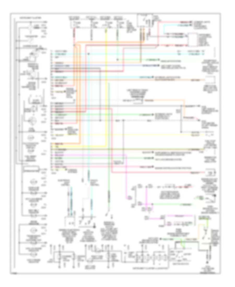
INSTRUMENT CLUSTER
Instrument Cluster Wiring Diagram for Ford Ranger Splash 1996
List of elements for Instrument Cluster Wiring Diagram for Ford Ranger Splash 1996:
- 4wd low range indicator
- check gauge
- speedometer
- (left rear of trans./ transfer case) vehicle speed sensor (vss)
- 3.0l/4.0l only
- 4.32k ohms
- 4w- abs
- 4wd hi range indicator
- 4x4 indicator switch (top front of transfer case assembly)
- Acc
- Air bag indi- cator
- Anti-lock brake indicator
- Anti-lock brakes system
- Anti-lock brakes system (rabs module pin2)
- Anti-theft system (rap module c409, pin 16)
- Body computer system (gem/ctm)
- Brake fluid level switch (brake fluid reser- voir)
- Brake indicator
- C168
- C214
- C215
- C216
- C223
- Charge gauge
- Charge indi- cator
- Daytime running lamps (drl) module (left side of lower radiator support)
- Door ajar indicator
- Electronic shift control
- Engine controls system (pcm pin 48)
- Engine controls system (pcm pin2)
- Engine coolant temperature gauge
- Engine coolant temperature sender (3.0l/4.0l: top front of engine; 2.3l: left rear of engine)
- Engine oil pressure gauge
- Engine oil pressure switch (4.0l: lower left front of engine; 3.0l: right rear of engine; 2.3l: left rear of cylinder head)
- Exterior lights (system multi- function sw)
- Exterior lights system multi-function sw)
- Fuel gauge
- Fuel pump module (top center of fuel tank)
- Fuel reset switch indicator
- Fuse 15a
- Fuse 7.5a
- G104 (top center of left fender apron)
- G108 (left side of upper radiator support)
- Generator/ voltage regulator
- Generic electronic module (gem)/ central timer module (ctm) (behind center of i/p)
- Gnd
- Head
- Headlights system
- High beam indi- cator
- Hot at all times
- Hot in hi or pass
- Hot in run or start
- I/p fuse panel (behind left side of i/p)
- Ignition switch
- Inertia fuel shut-off (ifs) (below glove box)
- Instrument cluster
- Instrument cluster illumination
- Instrument illumination dimming module (top left side of i/p)
- Interior lights system (instrument illumination)
- Left turn indicator
- Lock
- Main light switch
- Manual shift control
- Multi-function indicator lamp (mil)
- Off
- Ohms
- Park
- Park brake switch (on park brake assembly)
- Powertrain control module (pcm) (right rear of engine compt., through saftey wall)
- Rabs
- Rabs diode (engine compartment fuse/relay box)
- Red
- Right turn indicator
- Run
- Seat belt indicator
- Slosh module
- Start
- Tachometer
- Theft indi- cator
- Transmission control indicator lamp
- W/ drl
- W/o drl
- Warning systems
 Čeština
 Dansk
Dansk Deutsch
 Ελληνικά
 English
 English
 Español
 Suomi
Suomi Français
 עברית
עברית Hrvatski
 Magyar
 Italiano
 日本語
日本語 한국어
한국어 Nederlands
 Polski
 Português
 Português
 Română
 Русский
 Slovenčina
 Slovenščina
 Svenska
 Türkçe
 中文 (中国)
 Français