POWER DISTRIBUTION
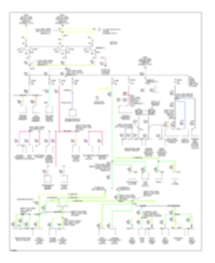
Power Distribution Wiring Diagram (1 of 3) for Ford Mustang Cobra 1998
 https://portal-diagnostov.com/license.html
Automotive Electricians Portal FZCO
Automotive Electricians Portal FZCO
https://portal-diagnostov.com/license.html
https://portal-diagnostov.com/license.html
Automotive Electricians Portal FZCO
Automotive Electricians Portal FZCO
List of elements for Power Distribution Wiring Diagram (1 of 3) for Ford Mustang Cobra 1998:
- (console panel harn, in fog lamp switch breakout) s305
- (dash panel to headlamp junction harn, near engine compt fuse box breakout)
- (eng cntrl sens harn, near air injection pump breakout) s145
- (radio amp harn, below side of rear seat)
- (radio amp harn, left side of trunk)
- 3.8l
- 4.6l
- Abs fuse 20a
- Abs fuse 40a
- Air injection reaction bypass
- Air injection reaction relay
- Alt fuse 20a
- Amplifier
- Anti-lock brake control module
- Audio fuse 25a
- Auxiliary power socket
- Battery
- Brake pedal position switch
- Brake pressure switch
- C282
- Cig illum fuse 30a
- Cigar lighter
- Constant control relay module
- Conv top fuse 25a
- Daytime running lights module
- Driver's seat control switch
- Drl, fog, horns fuse 20a
- Eec fuse 20a
- Electronic flasher
- Engine compartment fuse box (left side of engine compt)
- Fan circuit breaker 30a
- Fan fuse 60a
- Fog lamps relay (engine compt. fuse box)
- Front speaker subwoofer amplifier
- Fuel pump fuse 20a
- Fuse 15a
- G300 (below rear of center console)
- Generator/ voltage regulator
- Hd lps fuse 50a
- Horn relay (engine compt fuse box)
- Htd bl fuse 40a
- I/p fuse panel (below left side of dash)
- Ign sw fuse 40a
- Int lps fuse 25a
- Left power lumbar seat switch
- Lower relay
- Main light switch
- Power seat fuse 25a
- Powertrain control module
- Premium sound
- Raise relay
- Rear speaker subwoofer amplifier
- Rear window defrost control switch
- Red
- S102
- S108 (eng control sens harn, right side of eng compt)
- S109 (dash panel to headlamp junction harn, lower left side of eng compt)
- S111
- S207 (body main harn, behind right side of dash)
- S212 (radio amp harn, center of dash)
- S303
- S409 (near convert top motor breakout)
- S431
- S432
- Starter motor/ solenoid
- Starter relay
- Super sound
- Tan/ red
- Therm fuse 30a
- To fuse 8 (i/p fuse block) (diagram 2 of 3)
- To ignition switch (diagram 2 of 3)
- To ignition switch (diagram 3 of 3)
- To splice s215 (diagram 2 of 3)
- W/ drl only
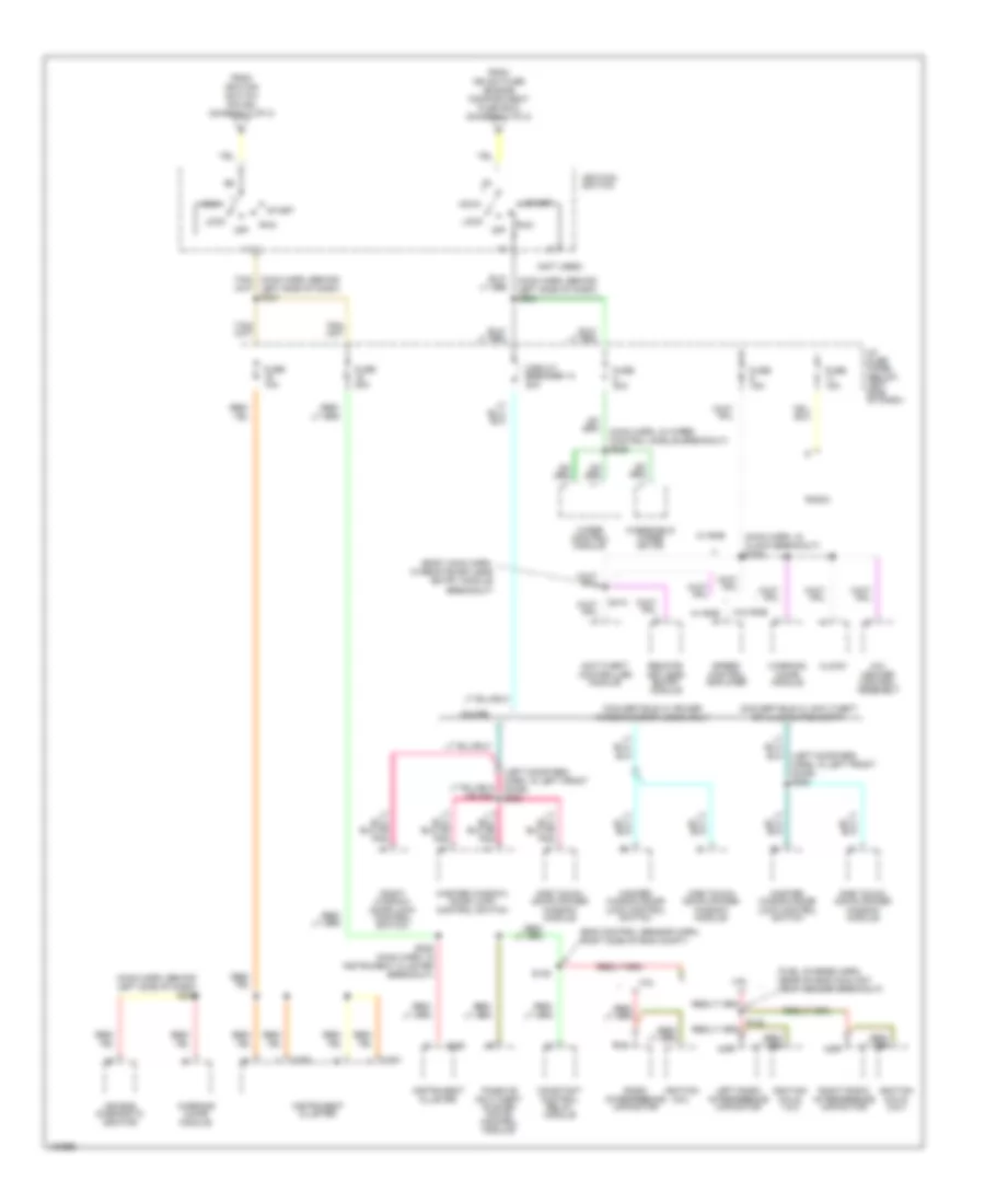
Power Distribution Wiring Diagram (2 of 3) for Ford Mustang Cobra 1998
List of elements for Power Distribution Wiring Diagram (2 of 3) for Ford Mustang Cobra 1998:
- (body main harn, behind left side of dash)
- (body main harn, behind left side of dash) s219
- (body main harn, left rear of trunk) s412
- (body main harn, left side of trunk)
- (body main harn, left side of trunk) s410
- (interior lamp harn, center of windshield header) s902
- (main harn, behind left side of dash) s210
- (main harn, near ignition switch breakout)
- (main harn, near lock breakout) s218
- A/c- heater control assembly
- A/t
- Acc
- Air bag diagnostic monitor
- Anti-lock brake control module
- Anti-theft controller module
- Backup lamp switch
- C250
- C257
- C276
- C281
- C401
- C404
- Cd player
- Circuit breaker 12 20a
- Convertible
- Convertible only
- Convertible top switch
- Coupe
- Coupe only
- Data link connector
- Daytime running lamps module
- Dome/ map lamp
- Dome/map lamp
- Electronic flasher
- From hd lps fuse (engine compt fuse box) (diagram 1 of 3)
- From ign sw fuse (engine compt fuse box) (diagram 1 of 3)
- Fuse 10a
- Fuse 15a
- Fuse 20a
- Fuse 30a
- Heater control assembly
- I/p fuse panel (below left side of dash)
- Ignition switch
- Instrument cluster
- Intake manifold runner control
- Left courtesy lamp switch
- Left vanity mirror lamp
- Lock
- Luggage compartment lamp switch
- M/t
- Main light switch
- Master window/ door lock control switch
- Module
- Multi- function switch
- Nca
- Off
- Passive anti- theft system control
- Power mirror switch
- Radio
- Rear window defrost control switch
- Remote/keyless entry module
- Right courtesy lamp switch
- Right vanity mirror lamp
- Right window/ door lock control switch
- Run
- S214 (main harn, near main light switch breakout)
- S215
- S216
- S220 (main harn, near multi- function sw breakout)
- S221 (main harn, near rear window defrost control switch breakout)
- S306
- S411
- S504 (left door window rag harn, in left front door)
- S902
- Shift lock actuator
- Sta
- Start
- Starting/ charging system
- To ignition switch (pin b5) (diagram 3 of 3)
- Transmission control switch
- Transmission range sensor
- Trunk lid release switch
- W/ a/c
- W/ remote keyless entry
- W/ remote/ keyless entry
- W/o a/c
- W/o remote keyless entry
- W/o remote/ keyless entry
Power Distribution Wiring Diagram (3 of 3) for Ford Mustang Cobra 1998
List of elements for Power Distribution Wiring Diagram (3 of 3) for Ford Mustang Cobra 1998:
- (body main harn, in remote/keyless entry module breakout)
- (eng control sensor harn, right side of eng compt)
- (fuel charge harn, near on eng coolant temp sender breakout)
- (left door reg harn, in left front door) s505
- (main harn, behind left side of dash) s224
- (main harn, behind left side of dash) s229
- (main harn, in clock breakout) s226
- (main harn, in wiper control module breakout) s225
- (not used)
- 3.8l
- 4.6l
- A/c- heater control assembly
- Acc
- Air bag diagnostic monitor
- Anti-theft controller module
- C250
- C251
- Circuit breaker 14 20a
- Clock
- Constant control relay module
- Convertible w/ anti-theft or illuminated entry
- Convertible w/ power windows/door locks only
- Coupe
- From ign sw fuse (engine compartment fuse box) (diagram 1 fo 3)
- From ignition switch (pin b4) (diagram 2 of 3)
- Fuse 10a
- Fuse 15a
- Fuse 20a
- Fuse 30a
- I/p fuse panel (below left side of dash)
- Ignition coil
- Ignition coils 1 & 2
- Ignition coils 3 & 4
- Ignition switch
- Instrument cluster
- Left radio interference capacitor
- Lock
- Master window/ door lock control switch
- Master window/door lock control switch
- Nca
- Off
- One touch down power window module
- Passive anti-theft system (pats) control module
- Radio
- Radio interference capacitor
- Remote/ keyless entry module
- Right radio interference capacitor
- Right window/ door lock control switch
- Run
- S105
- S228 (main harn, in instrument cluster breakout)
- S413
- Speed control amplifier
- Start
- W/ rke
- W/o rke
- Warning chime module
- Windshield wiper motor
- Wiper control module

 Čeština
 Dansk
Dansk Deutsch
 Ελληνικά
 English
 English
 Español
 Suomi
Suomi Français
 עברית
עברית Hrvatski
 Magyar
 Italiano
 日本語
日本語 한국어
한국어 Nederlands
 Polski
 Português
 Português
 Română
 Русский
 Slovenčina
 Slovenščina
 Svenska
 Türkçe
 中文 (中国)