POWER DISTRIBUTION
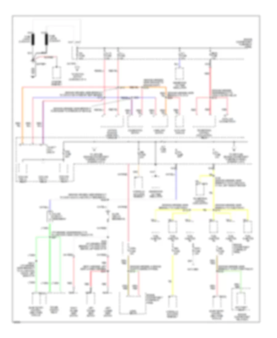
Power Distribution Wiring Diagram (1 of 4) for Mercury Villager LS 1997
List of elements for Power Distribution Wiring Diagram (1 of 4) for Mercury Villager LS 1997:
- (body harness, left seat jumper harness) s307
- (engine harness, in engine compt fuse/relay panel) s115
- (engine harness, near breakout to anti-theft relay) s133
- (engine harness, near breakout to conn c106 pcm relay) s112
- (engine harness, near breakout to conn c196 intake air temp sensor) s111
- (engine harness, near breakout to conn c242 in-line circuit breaker #1) s226
- (engine harness, near breakout to grommet to interior of vehicle)
- (engine harness, near breakout to injector #1) s114
- (engine harness, near breakout to injector #1) s118
- (engine harness, near grommet to engine compt) s123
- (i/p harness, near breakout to in-line conn c255m, right side of i/p) s227
- A/light (h/l) relay
- Abs fuse 20a
- Abs fuse 30a
- Alt fuse 10a
- Alt fuse 120a
- Anti-theft relay
- Autolamp module
- Battery
- Breakout to j/c 2) s225
- C2032
- C275
- Combination switch
- Cooling fan hi 1 relay
- Cooling fan hi 2 relay
- Cooling fan lo relay
- Data link connector #1
- Daytime running lamps (drl) module
- Eecs fuse 10a
- Engine compartment fuse/relay panel
- Engine compartment relay box
- Fuel injector #1
- Fuel injector #2
- Fuel injector #3
- Fuel injector #4
- Fuel injector #5
- Fuel injector #6
- Generator/ voltage regulator
- H/l l fuse 15a
- H/l r fuse 15a
- Headlamp switch
- Horn fuse 15a
- Horn relay
- Hydraulic actuator assembly
- Ign fuse 30a
- Inj fuse 10a
- Inline circuit breaker #1
- Inline circuit breaker #2
- Insp l fuse 15a
- Left lumbar seat switch
- Left power seat switch
- Nca
- Not used
- P/w fuse 30a
- Power window relay
- Powertrain control module (pcm)
- Powertrain control module (pcm) relay
- Rad fuse 65a
- Red
- Right power seat switch
- S113
- S129 (engine harness, near breakout to in-line conn c118m, left side of engine)
- S2012 (i/p harness, near breakout to in-line conn c2021m, left side of i/p)
- S223
- S228 (i/p harness, near breakout to conn c242, behind left side of i/p)
- Sec fuse 7.5a
- Smart entry control (sec)/timer module
- Starter assembly
- To def fuse (engine compartment fuse/relay panel) (diagram 3 of 4)
- To ignition switch (diagram 2 of 4)
- To j/b fuse (engine compartment fuse/relay panel) (diagram 2 of 4)
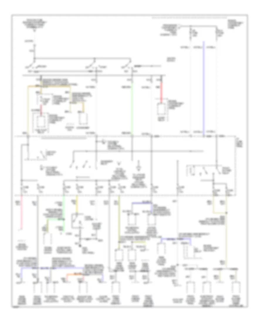
Power Distribution Wiring Diagram (2 of 4) for Mercury Villager LS 1997
List of elements for Power Distribution Wiring Diagram (2 of 4) for Mercury Villager LS 1997:
- (body harness, breakout to conn c254 power mirror switch) s279
- (engine harness, near breakout to conn c152 ignition coil) s120
- (engine harness, near breakout to conn c20204m, on anti-theft indicator) s241
- (i/p harness, near breakout to conn c2011 j/c #2) s250
- (i/p harness, near breakout to in-line conn c2021m, center of i/p) s2013
- (i/p harness, near breakout to in-line conn c255m, right side of i/p) s242
- A/c relay
- Acc
- Accessory relay
- Air bag diagnostic monitor
- Autolamp module
- Auxiliary power outlet
- Blw fuse 65a
- C202
- C2032
- C204
- C206
- C275
- Cigar lighter
- Condenser
- Daytime running lamps (drl) module
- Electronic automatic temperature control (eatc) assembly
- Engine compartment fuse/relay panel
- Engine compartment relay box
- Exhaust gas recirculation (egr) valve
- F pump fuse 15a
- From engine compartment c fuse/relay panel (diagram 1 of 4)
- From ign fuse (engine compartment fuse/relay panel) (diagram 1 of 4)
- Front blower motor
- Front blower motor/ speed controller
- Front blower relay
- Front climate control panel
- Front heated oxygen sensor
- Front washer motor
- Front wiper motor assembly
- Front wiper/ washer amplifier assembly
- Fuel pump relay
- Fuse 10a
- Fuse 20a
- Fuse 7.5a
- G200 (left kick panel)
- I/p fuse/ relay panel
- Idle air control (iac) valve #2
- Ignition coil
- Ignition relay
- Ignition switch
- Inhibit relay
- J/b fuse 100a
- Nca
- Nca (engine harness, near breakout to conn c202 engine compt fuse/relay panel) s119
- Off
- Power mirror switch
- Powertrain control module (pcm)
- Rear climate control panel
- Rear heated oxygen sensor
- Rear washer motor
- Rear wiper motor assembly
- Rear wiper/ washer amplifier
- Red
- Run
- S127
- S205
- S236 (i/p harness, near breakout to conn c256 front blower motor)
- S249 (i/p harness, near breakout to in-line conn c255m, right side of i/p)
- Smart entry control (sec)/ timer module
- Start
- Throttle position (tp) switch
- To fuse 10 (i/p fuse/ relay panel) (diagram 4 of 4)
- To fuse 27 (i/p fuse/ relay panel) (diagram 4 of 4)
- To liftgate defroster relay (i/p fuse/ relay panel) (diagram 3 of 4)
- To tail lamp relay (i/p fuse/ relay panel) (diagram 3 of 4)
- W/ eatc
- W/o eatc
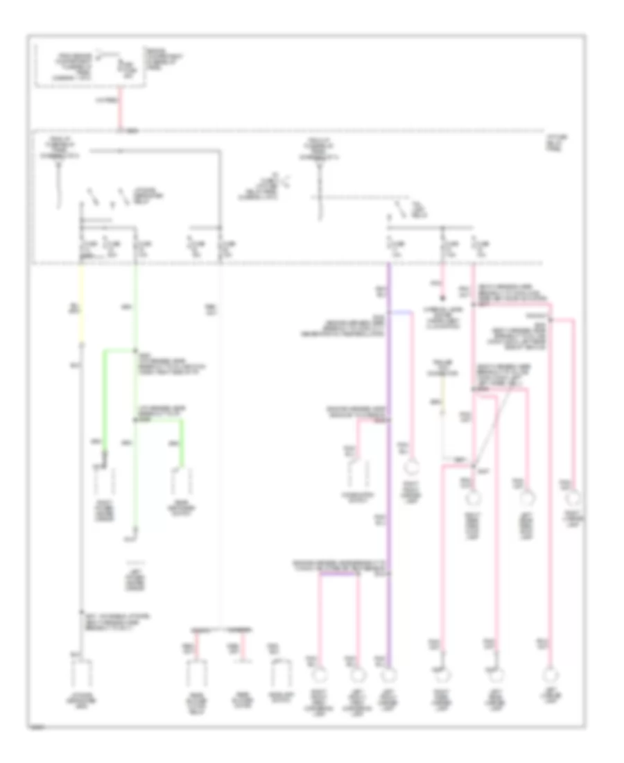
Power Distribution Wiring Diagram (3 of 4) for Mercury Villager LS 1997
List of elements for Power Distribution Wiring Diagram (3 of 4) for Mercury Villager LS 1997:
- (body harness, near breakout to conn c328, rear vent door actuator) s317
- (body harness, near breakout to in-line conn c332m, left left wheel well) s406
- (engine harness, near breakout to conn c196 intake air temp sensor) s124
- (engine harness, near grommet to interior) s125
- (i/p harness, near breakout to i/p) s255
- (moveable liftgate)
- C202
- Combination switch
- Def fuse 45a
- Engine compartment fuse/relay panel
- From engine compartment fuse/relay panel (diagram 1 of 4)
- From i/p fuse/relay panel (diagram 2 of 4)
- Fuse 10a
- Fuse 15a
- Fuse 20a
- Fuse 7.5a
- Headlamp switch
- I/p fuse/ relay panel
- Interior lamps system (instrument illumination)
- Left front marker lamp
- Left front park/ cornering lamp
- Left license lamp
- Left power/ heated mirror
- Left rear marker lamp
- Left rear park/ stop lamp
- Liftgate defroster grid
- Liftgate defroster relay
- Nca
- Pnk
- Rear blower motor
- Rear blower motor relay
- Rear defogger switch
- Right front marker lamp
- Right front park/ cornering lamp
- Right license lamp
- Right power/ heated mirror
- Right rear marker lamp
- Right rear park/ stop lamp
- S126 (engine harness, near breakout to conn c117 generator/voltage regulator)
- S252 (i/p harness, near breakout to in-line conn c255m, right side of i/p)
- S337 (body harness, near breakout to g411)
- S407
- S408 (body harness, near breakout to in-line conn c367m, left rear side of vehicle)
- Tail lamp relay
- To fuse 2 (i/p fuse/ relay panel (diagram 4 of 4)
- Trailer tow connector
- W/ eatc
- W/o eatc
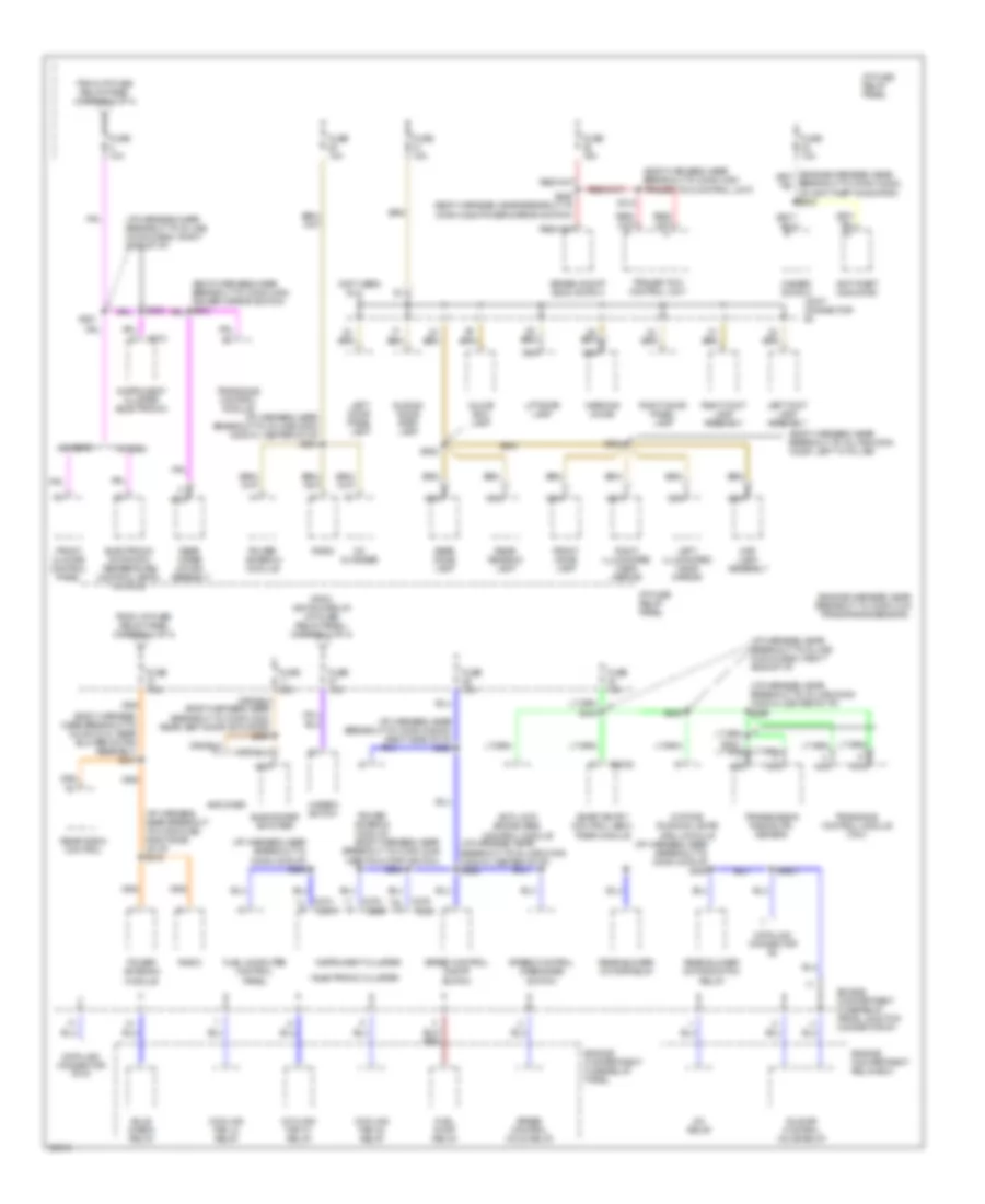
Power Distribution Wiring Diagram (4 of 4) for Mercury Villager LS 1997
List of elements for Power Distribution Wiring Diagram (4 of 4) for Mercury Villager LS 1997:
- (body harness, near breakout to conn c246 inertia cutoff switch)
- (body harness, near breakout to conn c318, rear blower motor assembly) s213
- (body harness, near breakout to conn c361 trailer tow control unit)
- (body harness, near breakout to in-line conn c238f, left "a" pillar)
- (engine harness, near breakout to conn c161 trans range sensor)
- (i/p harness, near breakout to conn c2024f, right side of i/p) s224
- (i/p harness, near breakout to conn c263, right side of i/p) s316
- (i/p harness, near breakout to conn c276 i/p) s259
- (i/p harness, near breakout to in-line conn c2021m, center of i/p) s234
- (i/p harness, near breakout to in-line conn c2021m, center of i/p) s258
- (i/p harness, near breakout to in-line conn c2021m, center of i/p) s296
- (i/p harness, near breakout to in-line conn c255m, right side of i/p)
- (not used)
- * electronic cluster
- A/c relay
- Amplifier
- Anti-lock brake (abs) control module
- Anti-theft indicator
- Brake on/off (boo) switch
- Bulb check relay
- C2032
- C266
- C268
- C270
- C272
- C274
- C276
- Cd changer
- Cooling fan h1 relay
- Cooling fan h2 relay
- Cooling fan lo relay
- Data link connector #2
- Data link connector (dlc)
- Daytime running lamps (drl) module
- Electronic automatic temperature control (eatc) module
- Engine compartment fuse/relay panel
- Engine compartment fuse/relay panel junction connector #1
- Engine compartment relay box
- From i/p fuse/ relay panel (diagram 2 of 4)
- From i/p fuse/ relay panel (diagram 3 of 4)
- From ignition relay (i/p fuse/ relay panel) (diagram 2 of 4)
- Front climate control panel
- Front dome lamp
- Fuel computer control panel
- Fuel pump relay
- Fuse 10a
- Fuse 15a
- Fuse 20a
- Fuse 7.5a
- Glove box lamp
- Hazard switch
- I/p fuse/ relay panel
- Idle air control valve relay
- Instrument cluster
- Instrument cluster (electronic)
- Joint connector #3
- Left door panel lamp
- Left foot lamp assembly
- Left illuminated visor mirror
- Liftgate lamp
- Map lamp assembly
- Nca
- Power antenna module
- Radio
- Rear blower motor relay
- Rear blower motor switch relay
- Rear dome lamp
- Rear radio control
- Rear reading lamp
- Rear wiper motor assembly
- Right door panel lamp
- Right foot lamp assembly
- Right illuminated visor mirror
- S200
- S231
- S232
- S239 (body harness, near breakout to conn c254 power mirror switch)
- S245
- S2621
- S312
- S902
- S904
- Sliding door step lamp
- Smart entry control (sec)/ timer module
- Speed control disengage switch
- Speed control hold relay
- Speed control on/off switch
- Subwoofer amplifier
- Trailer tow control unit
- Transaxle control module
- Transaxle control module (tcm)
- Transmission range (tr) sensor
- W/ eatc
- W/o eatc
- Warning chime

 Čeština
 Dansk
Dansk Deutsch
 Ελληνικά
 English
 English
 Español
 Suomi
Suomi Français
 עברית
עברית Hrvatski
 Magyar
 Italiano
 日本語
日本語 한국어
한국어 Nederlands
 Polski
 Português
 Português
 Română
 Русский
 Slovenčina
 Slovenščina
 Svenska
 Türkçe
 中文 (中国)