ELECTRONIC POWER STEERING
Active Power Steering Wiring Diagram for BMW 535i GT 2014


List of elements for Active Power Steering Wiring Diagram for BMW 535i GT 2014:
- (left kick panel) z10 5b
- Activation servomotor
- Active steering module (right footwell, under carpet)
- Active steering servo motor
- Central gateway module (left end of dash)
- Electric servo motor lock
- Flexray bus sig
- Fuse 40a
- Fuse 5a
- Gnd
- Hot at all times
- Hot w/ terminal 15n relay energized
- Junction box (right side of dash)
- Lock out
- Nca
- Pnk/red
- Rear axle king pin inclination control (on rear axle assembly)
- Servomotor sig
- Servomotor sig activation servomotor lock out
- Servomotor sply
- Terminal 15 sply
- Terminal 30 sply
- X87 1b
- Z10 50b
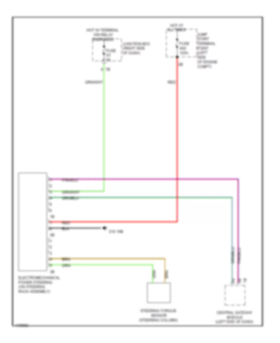
Electromechanical Power Steering Wiring Diagram for BMW 535i GT 2014
List of elements for Electromechanical Power Steering Wiring Diagram for BMW 535i GT 2014:
- Central gateway module (left end of dash)
- Electromechanical power steering (on steering rack assembly)
- Fuse 125a
- Fuse 5a
- Hot at all times
- Hot w/ terminal 15n relay energized
- Jump start terminal point (left side of engine compt)
- Junction box (right side of dash)
- Red
- Steering-torque sensor (steering column)
- Z10 19b
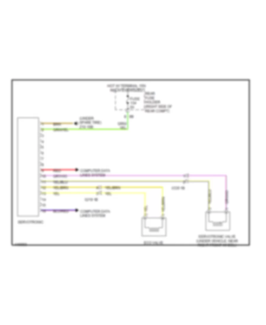
Servotronic Wiring Diagram for BMW 535i GT 2014
List of elements for Servotronic Wiring Diagram for BMW 535i GT 2014:
- (under spare tire) z10 16b
- Computer data lines system
- Eco valve
- Fuse 5a
- Hot w/ terminal 15n relay energized
- Rear fuse holder (right side of rear compt)
- Red
- Servotronic
- Servotronic valve (under vehicle, near right front wheel)
- X219 1b
- X335 1b

 Čeština
 Dansk
Dansk Deutsch
 Ελληνικά
 English
 English
 Español
 Suomi
Suomi Français
 עברית
עברית Hrvatski
 Magyar
 Italiano
 日本語
日本語 한국어
한국어 Nederlands
 Polski
 Português
 Português
 Română
 Русский
 Slovenčina
 Slovenščina
 Svenska
 Türkçe
 中文 (中国)