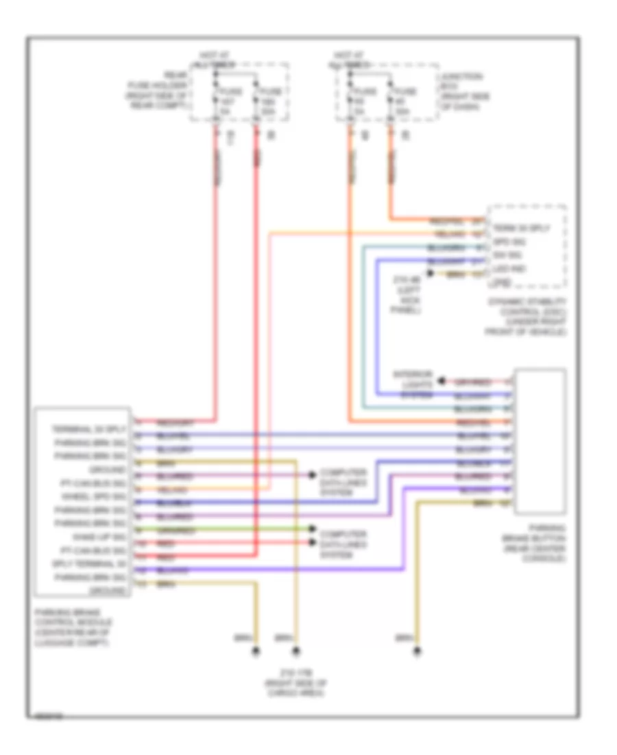
SHIFT INTERLOCK
Shift Interlock Wiring Diagram for BMW 535i GT 2014
List of elements for Shift Interlock Wiring Diagram for BMW 535i GT 2014:
- 11b
- Computer data lines system
- Dynamic stability control (dsc) (under right front of vehicle)
- Fuse 30a
- Fuse 5a
- Gnd
- Ground
- Hot at all times
- Interior lights system
- Junction box (right side of dash)
- Led ind
- Parking brake button (rear center console)
- Parking brake control module (center rear of luggage compt)
- Parking brk sig
- Pt-can bus sig
- Rear fuse holder (right side of rear compt)
- Red
- Spd sig
- Sply terminal 30
- Sw sig
- Term 30 sply
- Terminal 30 sply
- Wake-up sig
- Wheel spd sig
- Z10 17b (right side of cargo area)
- Z10 4b (left kick panel)
 Čeština
 Dansk
Dansk Deutsch
 Ελληνικά
 English
 English
 Español
 Suomi
Suomi Français
 עברית
עברית Hrvatski
 Magyar
 Italiano
 日本語
日本語 한국어
한국어 Nederlands
 Polski
 Português
 Português
 Română
 Русский
 Slovenčina
 Slovenščina
 Svenska
 Türkçe
 中文 (中国)
 Français