SUPPLEMENTAL RESTRAINTS
Supplemental Restraint Wiring Diagram, with Side Airbag for Mazda 626 ES 2002
 https://portal-diagnostov.com/license.html
Automotive Electricians Portal FZCO
Automotive Electricians Portal FZCO
https://portal-diagnostov.com/license.html
https://portal-diagnostov.com/license.html
Automotive Electricians Portal FZCO
Automotive Electricians Portal FZCO
List of elements for Supplemental Restraint Wiring Diagram, with Side Airbag for Mazda 626 ES 2002:
- A/b & abs fuse 8 10a
- Air bag indicator
- Clock spring
- Driver-side air bag module
- Driver-side side air bag module
- Driver-side side air bag sensor (at base of left "b" pillar)
- Engine fuse 19 10a
- G13 (behind right side of dash)
- G8 (behind left kick panel)
- G9 (under driver's seat)
- Hot in run or start
- Inflator
- Instrument cluster
- Jb-01
- Jb-07
- Jb-08
- Jc05
- Jc06
- Joint box (behind left side of dash)
- Meter fuse 4 10a
- Nca
- Note: a shorting bar connector is used on sas control module when module is disconnected from harness between pins q & s
- Passenger side-side air bag module
- Passenger-side air bag module
- Passenger-side side air bag sensor (at base of right "b" pillar)
- Red
- Sas control module (under center of dash)
- Shorting bar
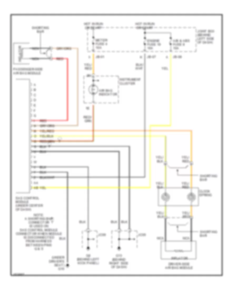
Supplemental Restraint Wiring Diagram, without Side Airbag for Mazda 626 ES 2002
List of elements for Supplemental Restraint Wiring Diagram, without Side Airbag for Mazda 626 ES 2002:
- (under driver's seat) g10
- A/b & abs fuse 8 10a
- Air bag indicator
- Clock spring
- Driver-side air bag module
- Engine fuse 19 10a
- G13 (behind right side of dash)
- G8 (behind left kick panel)
- Hot in run or start
- Inflator
- Instrument cluster
- Jb-01
- Jb-07
- Jb-08
- Jc05
- Jc06
- Joint box (behind left side of dash)
- Meter fuse 4 10a
- Nca
- Note: a shorting bar connector is used on sas control module connector when module is disconnected from harness between pins q & s
- Passenger-side air bag module
- Red
- Sas control module (under center of dash)
- Shorting bar

 Čeština
 Dansk
Dansk Deutsch
 Ελληνικά
 English
 English
 Español
 Suomi
Suomi Français
 עברית
עברית Hrvatski
 Magyar
 Italiano
 日本語
日本語 한국어
한국어 Nederlands
 Polski
 Português
 Português
 Română
 Русский
 Slovenčina
 Slovenščina
 Svenska
 Türkçe
 中文 (中国)