СИСТЕМА ПЕРЕДАЧИ ДАННЫХ
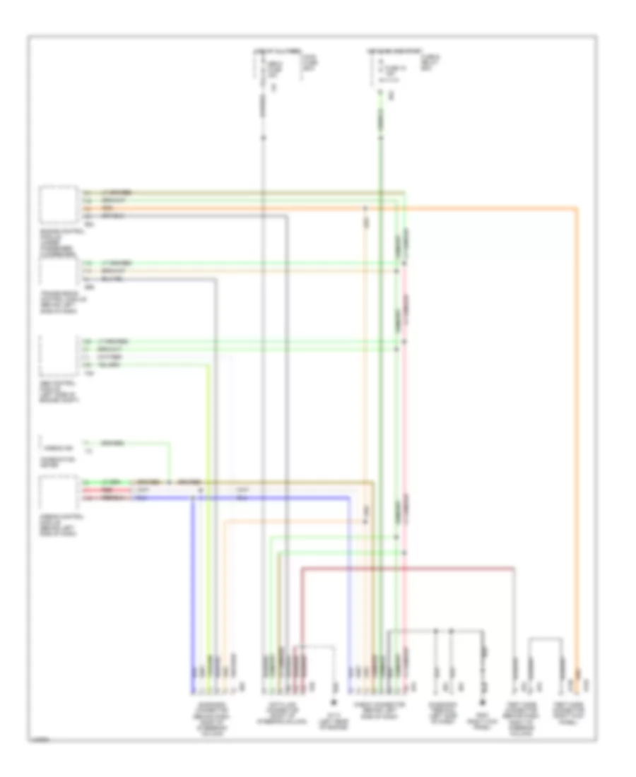
Электросхема компьютерной линии передачи данных CAN для Subaru Impreza RS 1998
Электросхема компьютерной линии передачи данных CAN для Subaru Impreza RS 1998 - Список элементов:
- (behind dash, right of steeering column)
- Abs control module (left side of engine compt)
- Airbag control module (behind left side of dash)
- Airbag ind
- B125
- B126
- B40
- B52
- B56
- B75
- B76
- B79
- B81
- B82
- B84
- Check connector (behind left side of dash)
- Combination meter
- Data link connector (right of steering column)
- Diagnosis connector
- Diagnosis terminal (left side of dash)
- Engine control module (under passenger floorboard)
- F37
- F49
- Fuse & relay box
- Fuse 18 15a
- G114 (left rear of engine)
- G203 (right kick panel)
- Hot at all times
- Hot in on and start
- I12
- Main fuse box
- Red
- Sbf-5 fuse 30a
- Test mode connector (behind dash, right of steering column)
- Test mode connector (right kick panel)
- Transmission control module (behind left side of dash)
 Čeština
 Dansk
Dansk Deutsch
 Ελληνικά
 English
 English
 Español
 Suomi
Suomi Français
 עברית
עברית Hrvatski
 Magyar
 Italiano
 日本語
日本語 한국어
한국어 Nederlands
 Polski
 Português
 Português
 Română
 Русский
 Slovenčina
 Slovenščina
 Svenska
 Türkçe
 中文 (中国)
 Français