ENGINE PERFORMANCE
1.4L TURBO HYBRID
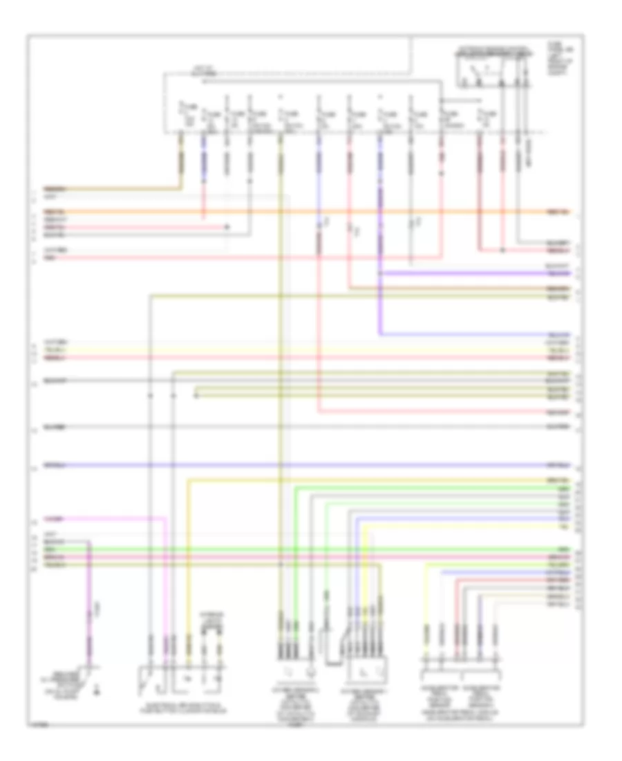
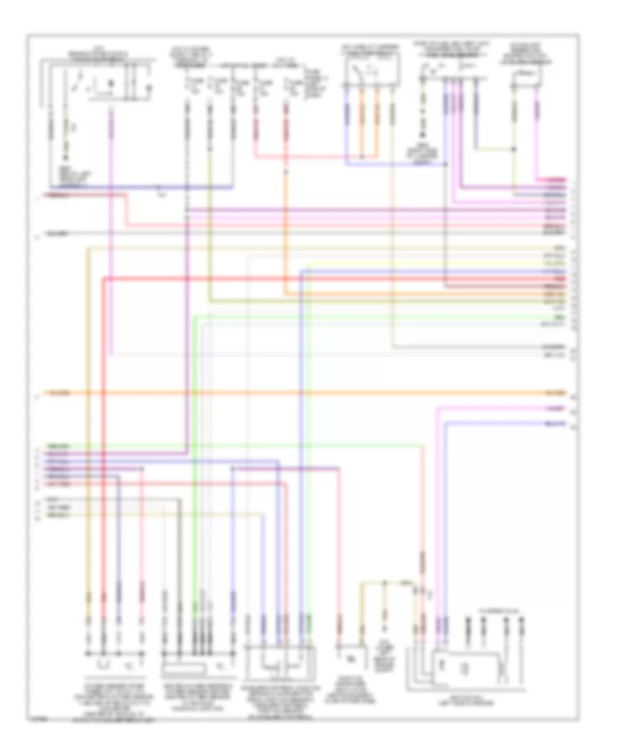
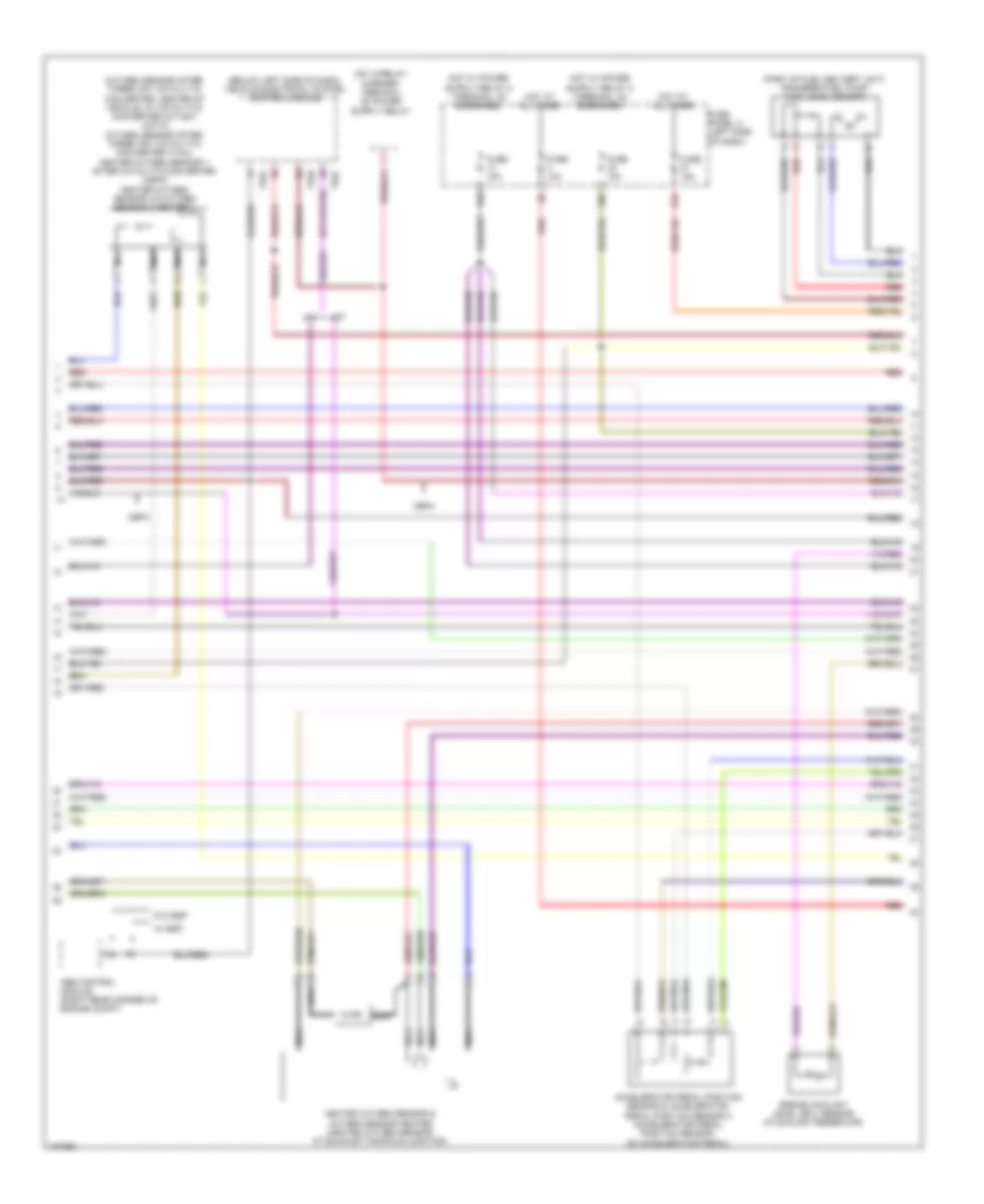
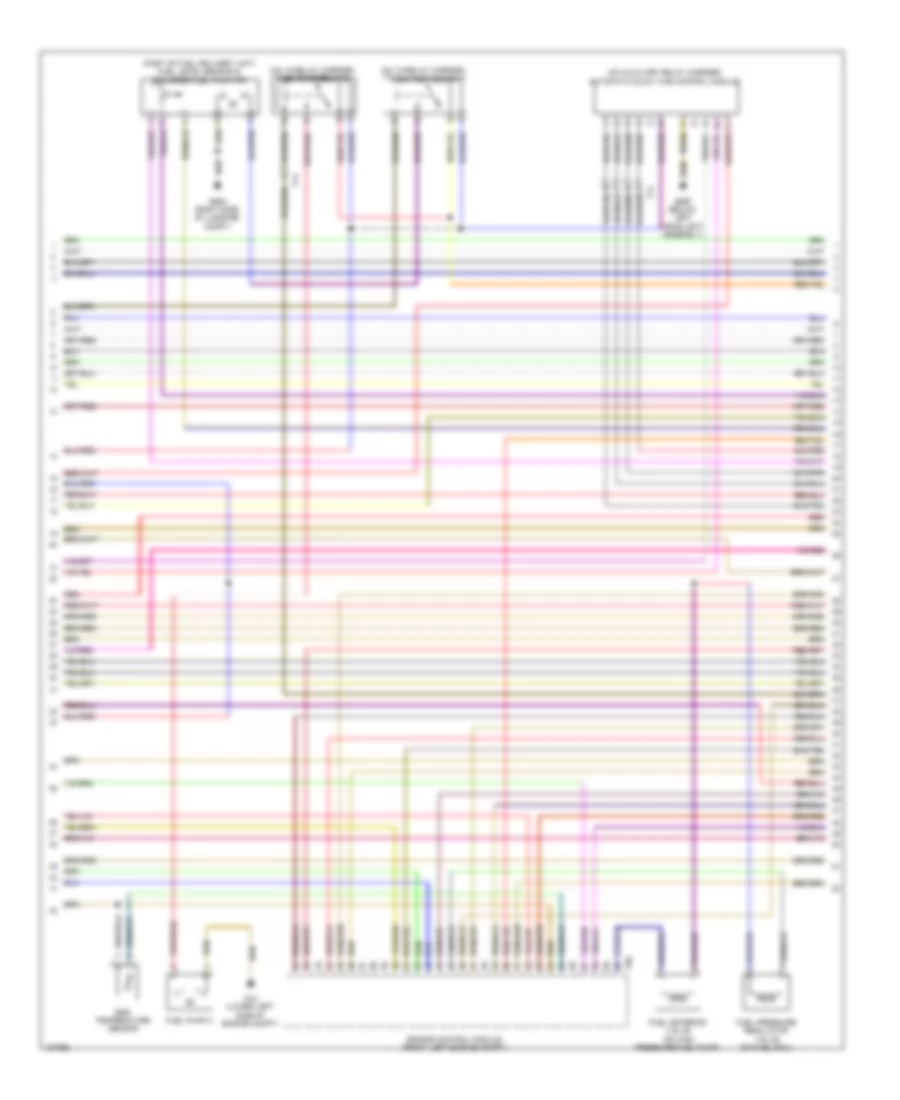
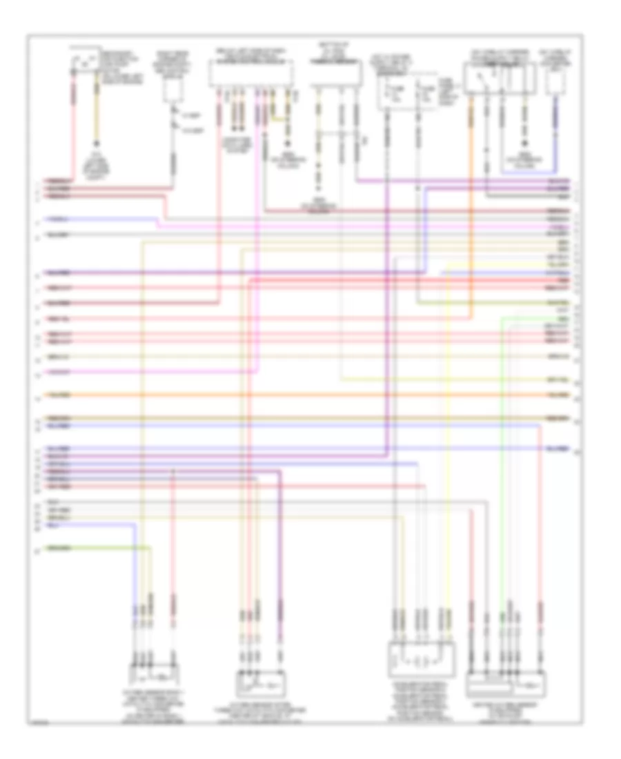
1.4L Turbo Hybrid, Engine Performance Wiring Diagram (1 of 8) for Volkswagen Jetta S 2013
 https://portal-diagnostov.com/license.html
Automotive Electricians Portal FZCO
Automotive Electricians Portal FZCO
https://portal-diagnostov.com/license.html
https://portal-diagnostov.com/license.html
Automotive Electricians Portal FZCO
Automotive Electricians Portal FZCO
List of elements for 1.4L Turbo Hybrid, Engine Performance Wiring Diagram (1 of 8) for Volkswagen Jetta S 2013:
- (below left headlight assembly) g655
- (if equipped) brake booster relay
- (integral to brake lamp switch) brake pedal switch
- (lower left side of engine compt) g12
- (on intake air duct) charge air pressure sensor
- (on lower left side of engine) secondary air injection pump motor
- (relay carrier on electronics box) secondary air injection pump relay
- (right side of transmission) brake system vacuum pump
- Abs control module (right rear corner of engine compt)
- Brake booster pressure sensor (left rear corner of engine compt)
- Cooling fans system
- Engine control module (front left engine compt)
- Engine coolant temperature sensor (radiator)
- Evap canister purge regulator valve 2
- Fuel tank pressure sensor (on fuel rail)
- G12 (lower left side of engine compt)
- G44 (lower left "a" pillar)
- Leak detection pump (in right rear wheelwell, near fuel filler door)
- Nca
- Oxygen sensor 1 after catalytic converter (at catalytic converter 2 outlet)
- Red
- T14
- T14hy
- T2kh
- T94
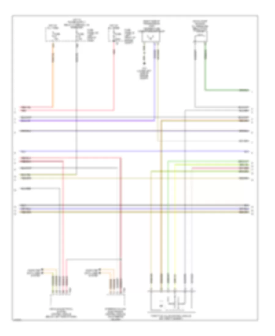
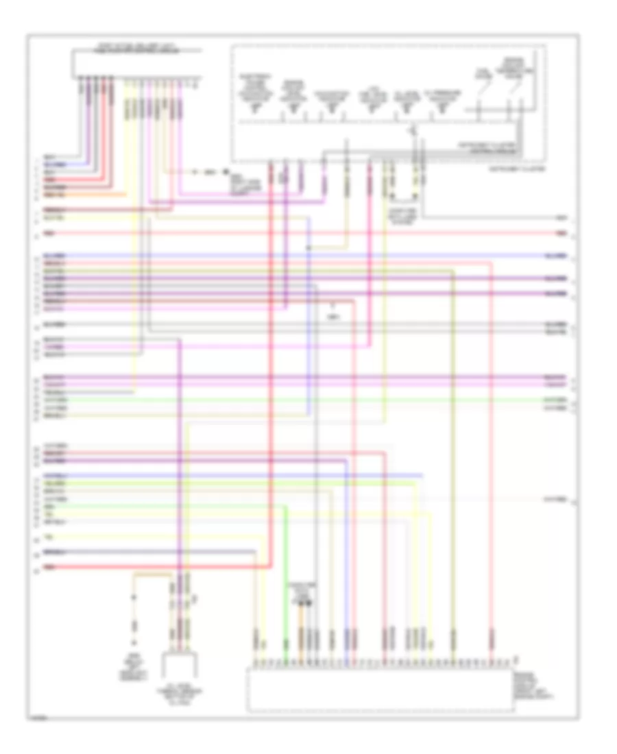
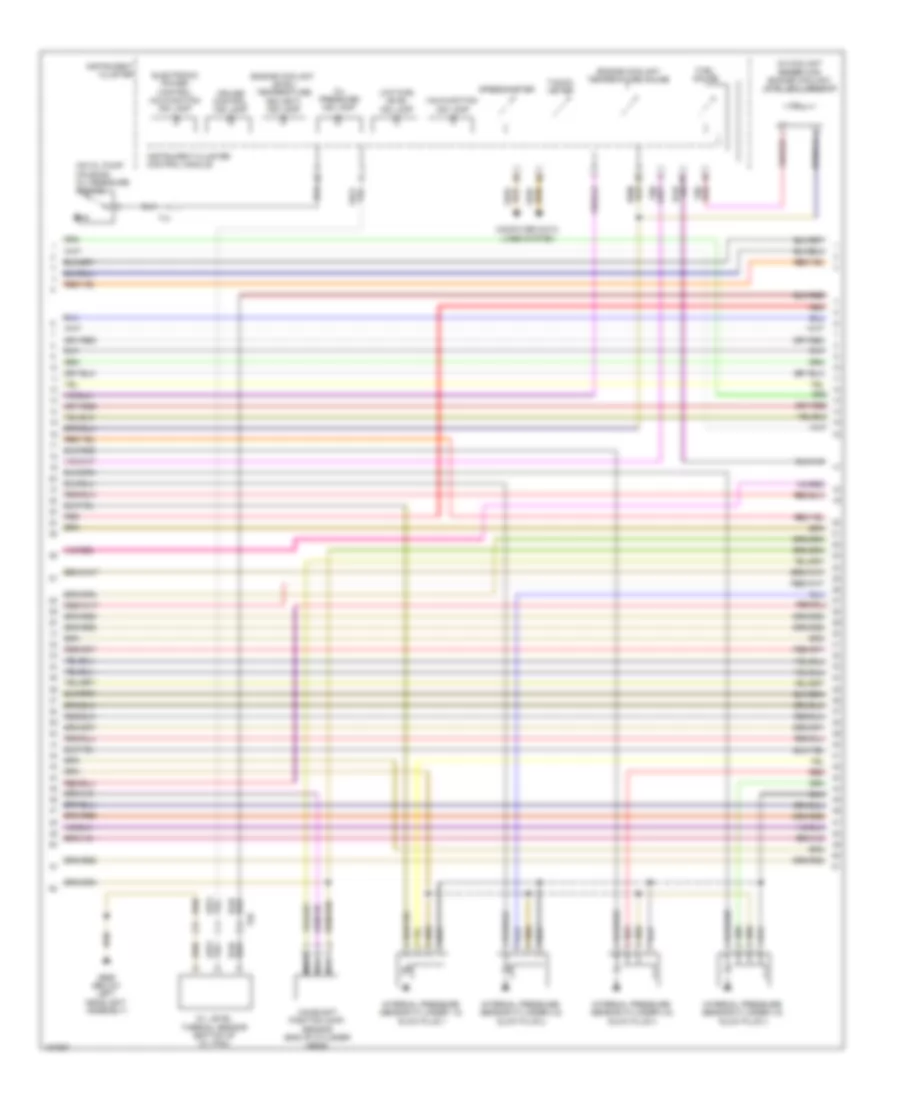
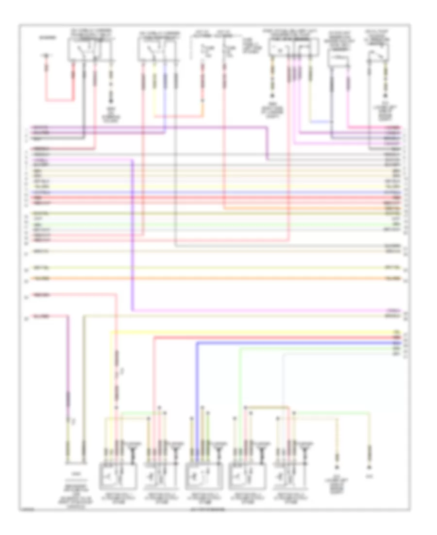
1.4L Turbo Hybrid, Engine Performance Wiring Diagram (2 of 8) for Volkswagen Jetta S 2013
List of elements for 1.4L Turbo Hybrid, Engine Performance Wiring Diagram (2 of 8) for Volkswagen Jetta S 2013:
- (not used)
- 10a
- 13a
- 14a
- 26a
- Accelerator pedal module (on accelerator pedal)
- Accelerator pedal position sensor
- Accelerator pedal position sensor 2
- Electrical drive button & push button illumination bulb
- Fuse 10a
- Fuse 10a/ 15a
- Fuse 20a
- Fuse 40a/50a
- Fuse 5a
- Fuse 5a/ 20a
- Fuse 5a/10a/ 15a
- Fuse 5a/10a/ 15a/20a
- Fuse 5a/10a/ 20a
- Fuse panel sb (left front of engine compt)
- Hot at all times
- Interior lights system
- Nca
- Oxygen sensor 1 before catalytic converter (at exhaust manifold)
- Oxygen sensor 2 before catalytic converter (at catalytic converter 2 inlet)
- Red
- Reduced oil pressure switch (on oil pump housing)
- T14
- T14hy
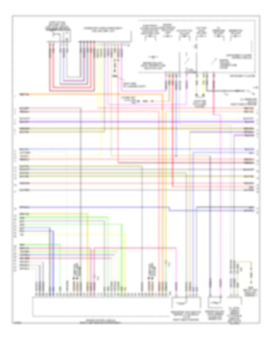
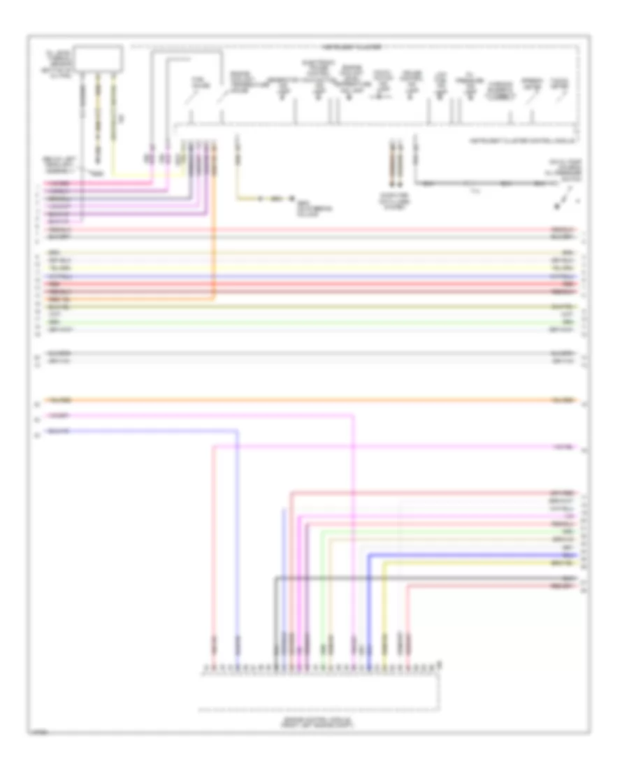
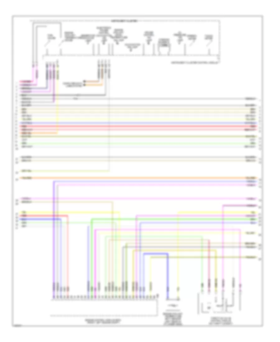
1.4L Turbo Hybrid, Engine Performance Wiring Diagram (3 of 8) for Volkswagen Jetta S 2013
List of elements for 1.4L Turbo Hybrid, Engine Performance Wiring Diagram (3 of 8) for Volkswagen Jetta S 2013:
- (lower left "a" pillar) g44
- (part of fuel delivery unit) fuel level sensor/ transfer fuel pump
- (right side of luggage compt)
- (under right side of rear seat) fuel delivery unit
- Computer data lines system
- Data lines computer
- Electronic power control malfunction indicator lamp
- Engine control module (front left engine compartment)
- Engine coolant level sensor (in coolant reservoir)
- Engine coolant level/temperature indicator lamp
- Engine coolant temperature gauge
- Engine electronics indicator lamp
- Fuel gauge
- G655 (below left headlight assembly)
- G682
- Generator ind lamp
- Instrument cluster
- Instrument cluster control module
- Low fuel level ind lamp
- Malfunction ind lamp
- Oil level thermal sensor (w/ flexible service) (bottom of oil pan)
- Oil pressure ind lamp
- Oil pressure switch (right side of engine)
- Red
- Secondary air injection sensor 1 & solenoid valve (right side of engine)
- System
- System data lines computer
- T14
- T6z
- T94
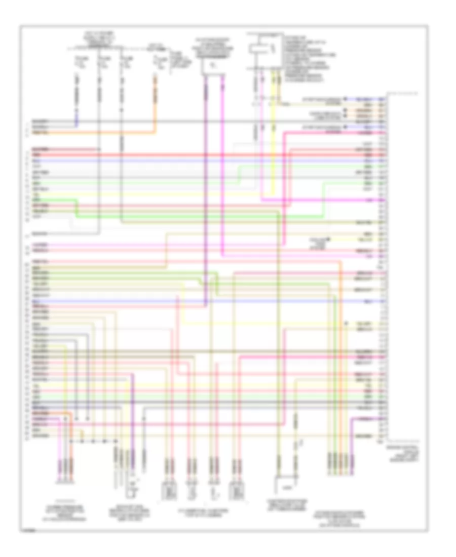
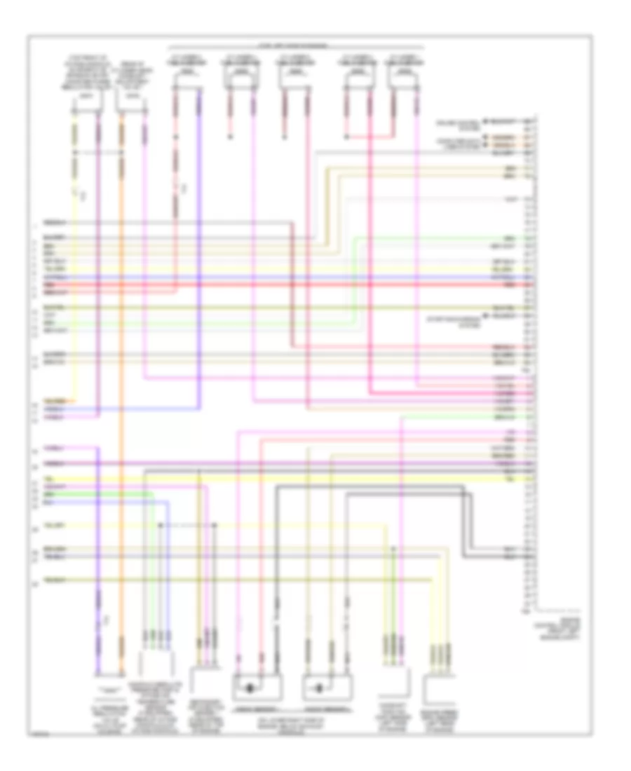
1.4L Turbo Hybrid, Engine Performance Wiring Diagram (4 of 8) for Volkswagen Jetta S 2013
List of elements for 1.4L Turbo Hybrid, Engine Performance Wiring Diagram (4 of 8) for Volkswagen Jetta S 2013:
- (left front of engine) low temperature circuit coolant pump
- 13b
- 14b
- 56a
- 56b
- 59a
- 59b
- Battery fan 1
- Battery fuse panel terminal 30 wire junction
- C1s
- Computer data lines system
- D1s
- Fan activation relay
- Fuel pressure regulator valve (left rear of engine)
- Fuse 10a
- Fuse 15a
- Fuse 5a
- Fuse 80a b1a
- Fuse panel sc (left side of dash)
- G12 (lower left side of engine compt)
- G662 (left side of luggage compt)
- G701
- High voltage system fuse
- High voltage system maintenance connector
- Hot at all times
- Hybrid battery unit (luggage compt)
- Nca
- Pilot line connector 1
- Red
- T14ax
- T4lh
- T8ax
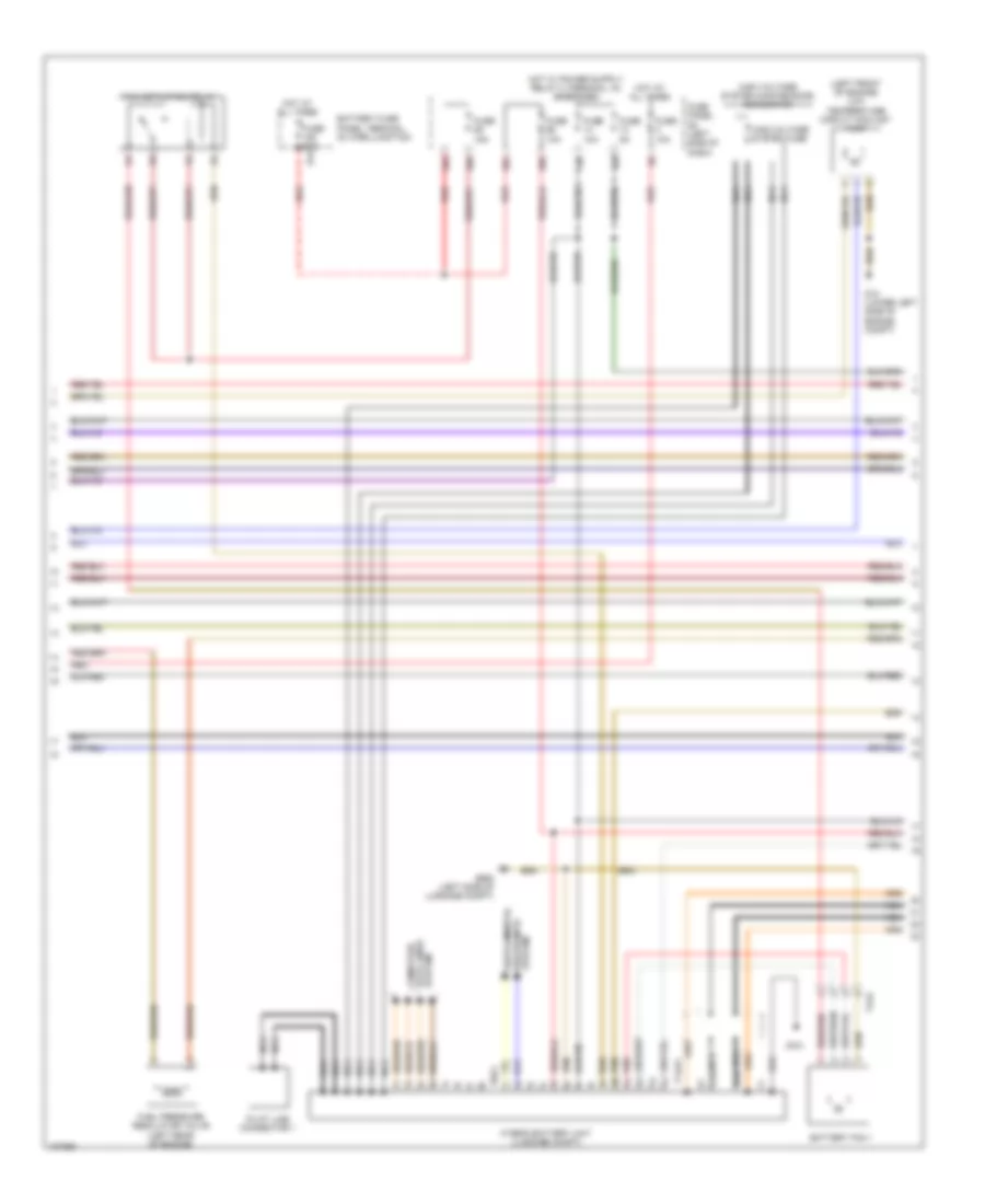
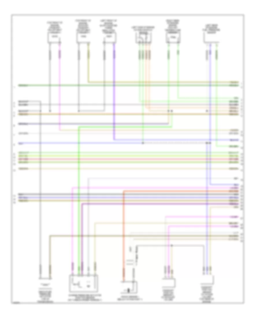
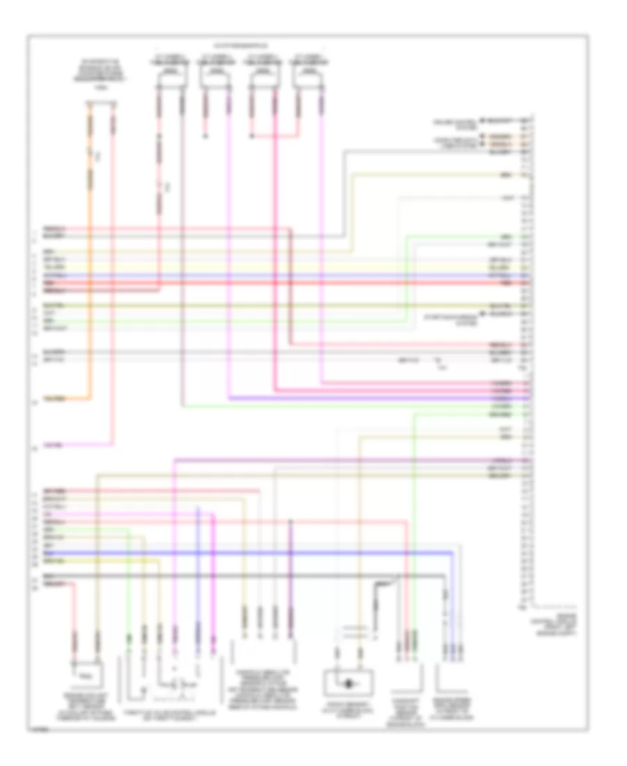
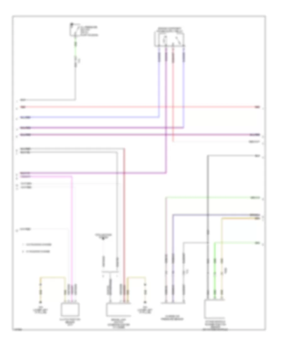
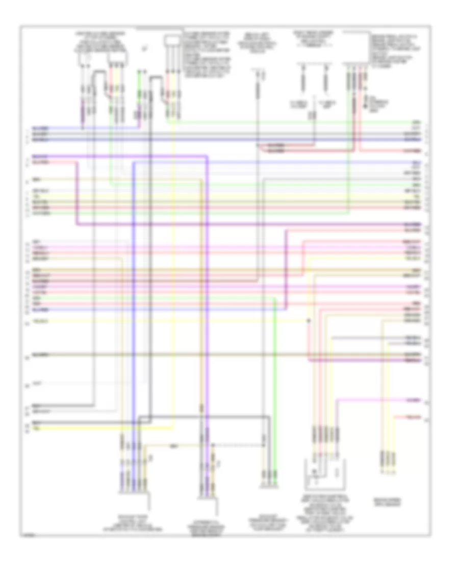
1.4L Turbo Hybrid, Engine Performance Wiring Diagram (5 of 8) for Volkswagen Jetta S 2013
List of elements for 1.4L Turbo Hybrid, Engine Performance Wiring Diagram (5 of 8) for Volkswagen Jetta S 2013:
- (left side of transmission) three-phase current drive
- (on electric air conditioner compressor) a/c compressor control module
- B1s
- C1s
- Climatronic control module
- Computer data lines system
- D1s
- D2s
- Data lines computer
- E1s
- E2s
- E3s
- Electric drive power & control electronics
- G12 (lower left side of engine compt)
- G655 (below left headlight assembly)
- Nca
- Red
- System
- T14hy
- T20c
- T28jx
- T2va
- T2vx
- T4bk
- T4hy
- T4jx
- T4vx
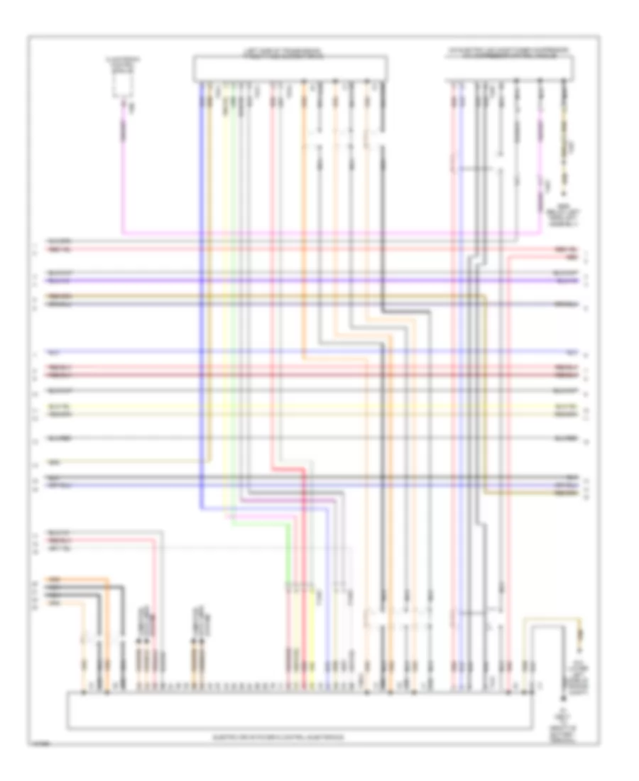
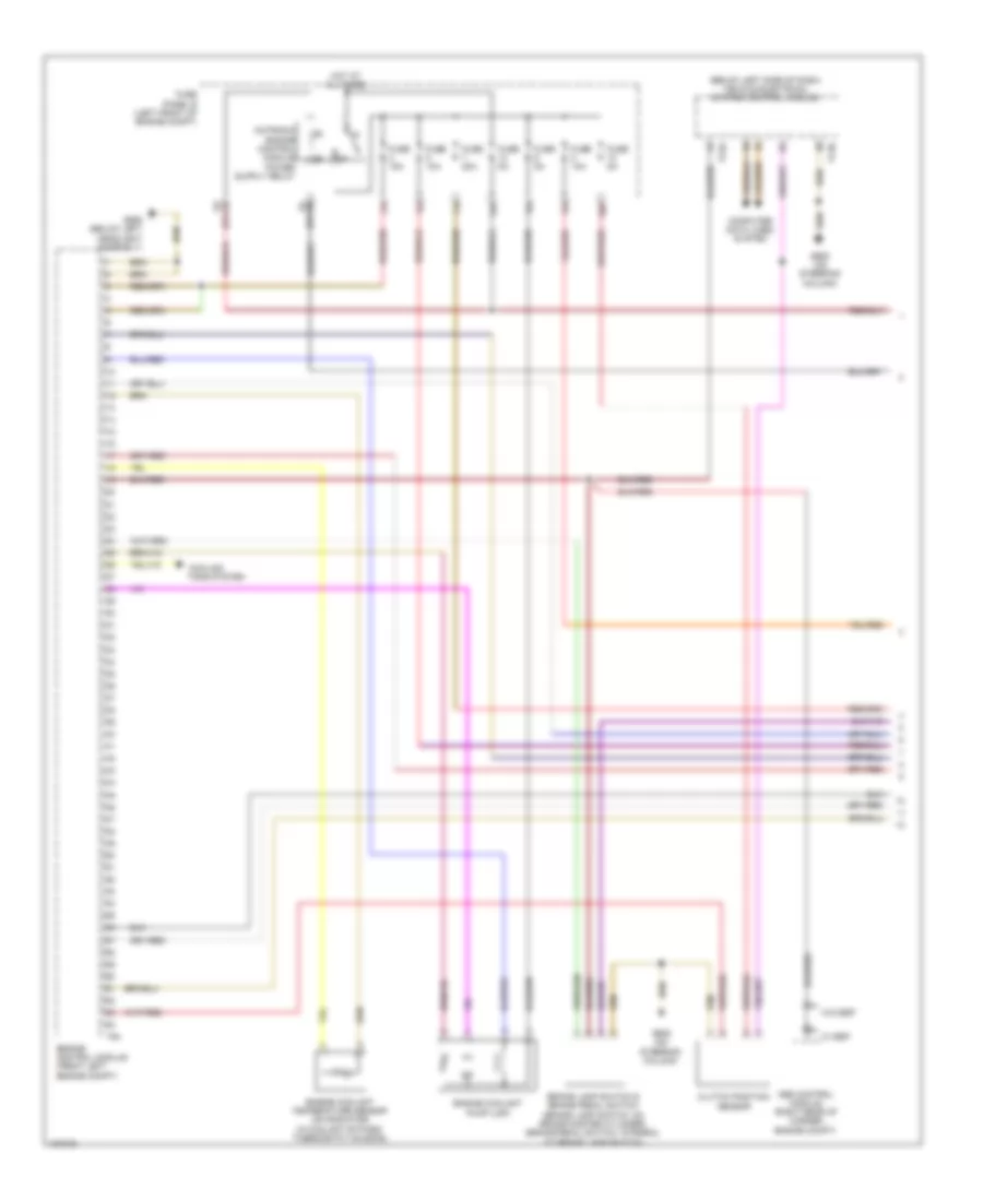
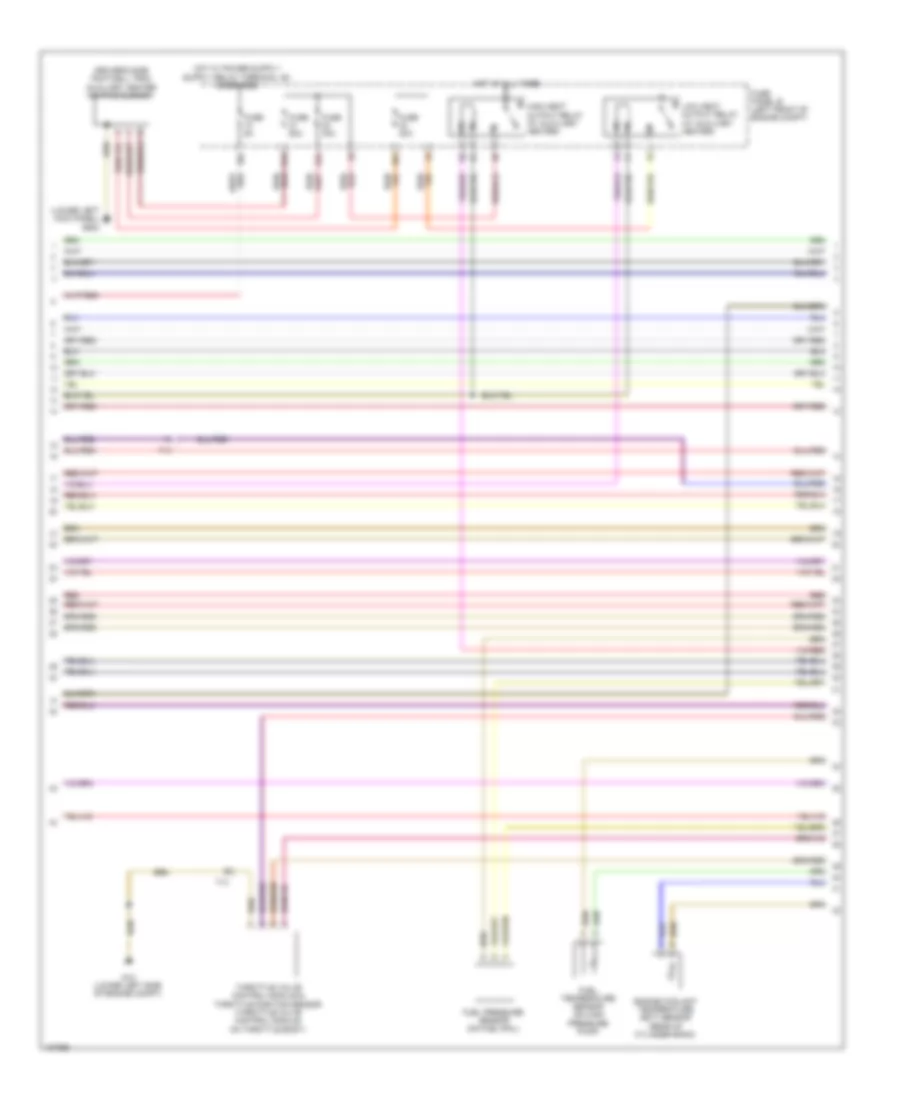
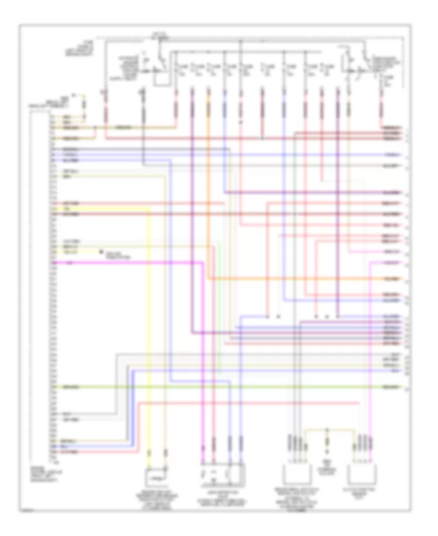
1.4L Turbo Hybrid, Engine Performance Wiring Diagram (6 of 8) for Volkswagen Jetta S 2013
List of elements for 1.4L Turbo Hybrid, Engine Performance Wiring Diagram (6 of 8) for Volkswagen Jetta S 2013:
- (on oil pump housing) oil pressure regulation valve
- (right side of transmission) high temperature circuit coolant pump
- 16b
- 47b
- Computer data lines system
- Fuse 10a
- Fuse 15a
- Fuse 200a
- Fuse panel b (left front of engine compt)
- Fuse panel sc (left side of dash)
- G12 (lower left side of engine compt)
- Hot at all times
- Red
- Steering column electronics control module (on steering column)
- T16l
- T52c
- Throttle valve control module (on throttle body)
- Vehicle electrical system control module (below left side of dash)
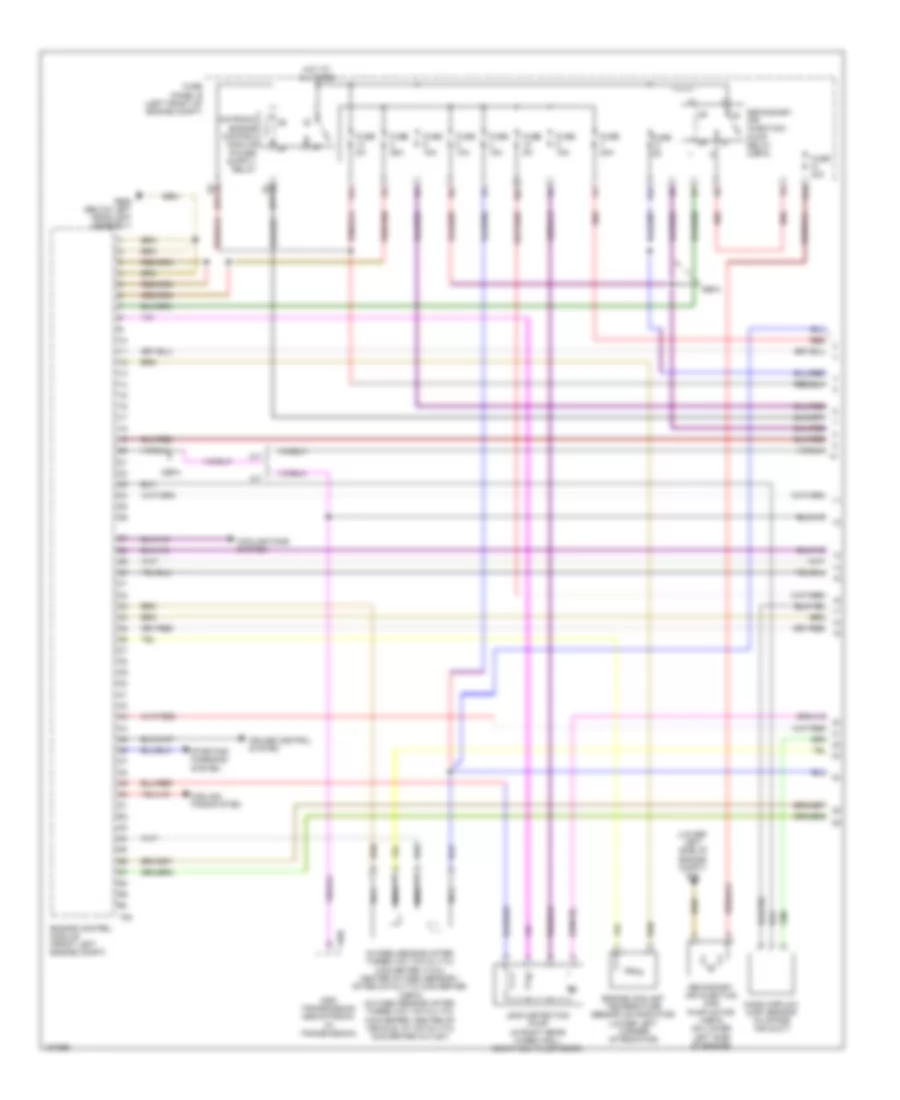
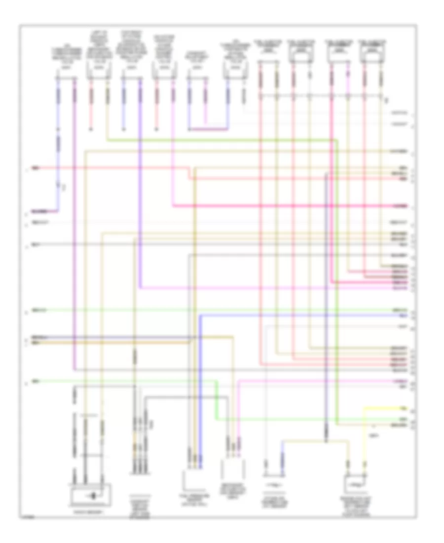
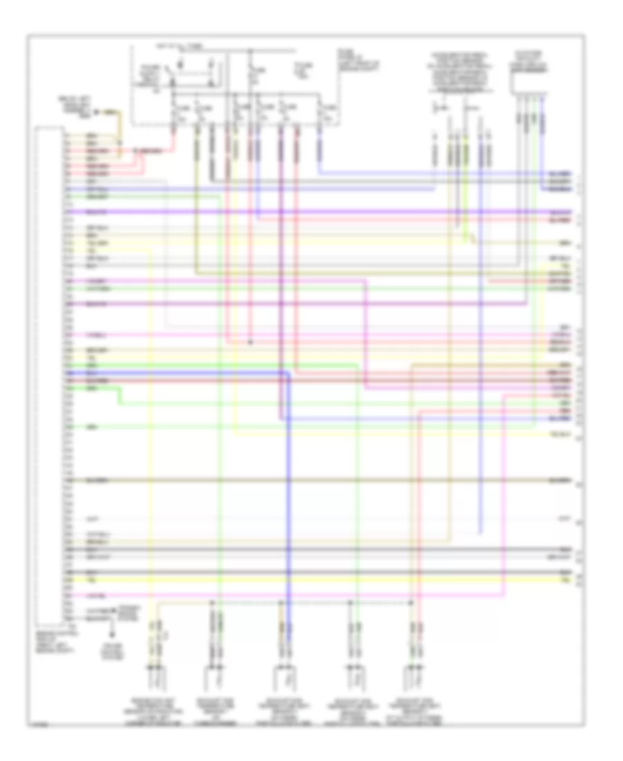
1.4L Turbo Hybrid, Engine Performance Wiring Diagram (7 of 8) for Volkswagen Jetta S 2013
List of elements for 1.4L Turbo Hybrid, Engine Performance Wiring Diagram (7 of 8) for Volkswagen Jetta S 2013:
- (left front of engine) evap canister purge regulator valve 1
- (left rear of engine) fuel pressure sensor
- (left side of engine)
- (right rear of engine) engine coolant temperature sensor
- (top front of engine) camshaft adjustment valve 1
- (top front of engine) exhaust camshaft adjustment valve 1
- Camshaft position sensor (w/ intake valves) (top rear of engine)
- Camshaft position sensor 3 (w/ exhaust valves)
- Charge pressure actuator position sensor (on turbocharger assembly)
- Decoupler pressure actuator (top of transmission)
- Intake manifold sensor
- Knock sensor 1 (below intake port 1)
- Nca
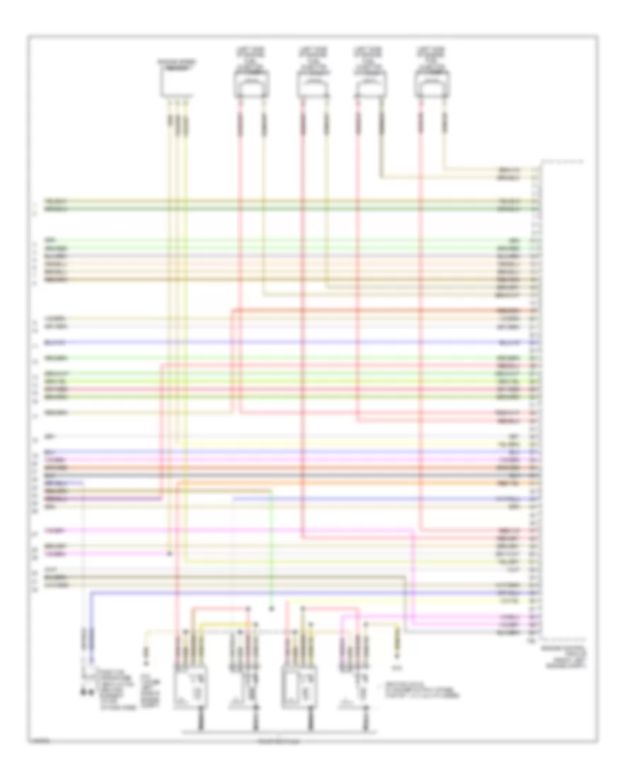
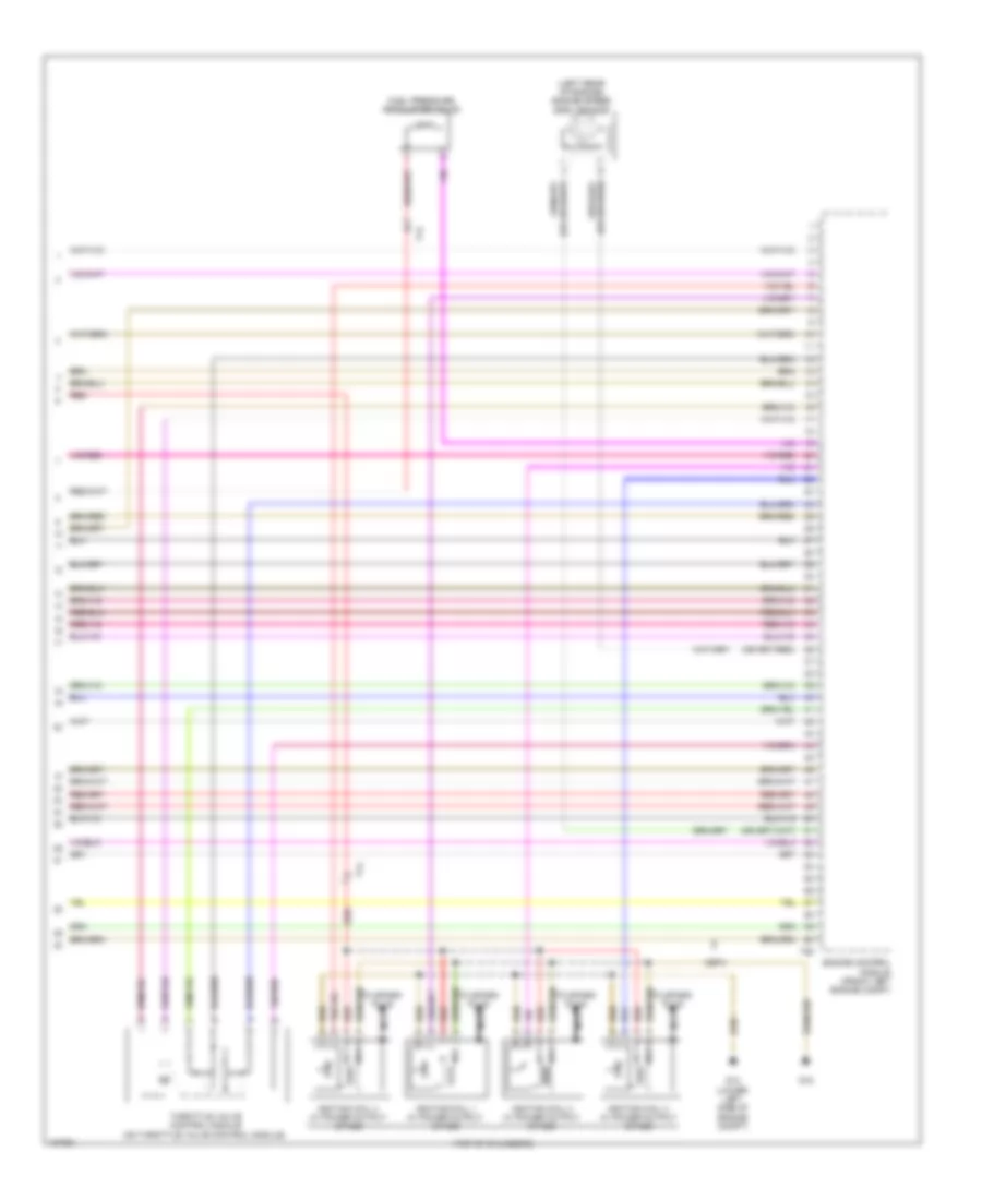
1.4L Turbo Hybrid, Engine Performance Wiring Diagram (8 of 8) for Volkswagen Jetta S 2013
List of elements for 1.4L Turbo Hybrid, Engine Performance Wiring Diagram (8 of 8) for Volkswagen Jetta S 2013:
- (left side of engine)
- (left side of engine) fuel injector cylinder 2
- (left side of engine) fuel injector cylinder 3
- (left side of engine) fuel injector cylinder 4
- Engine control module (front left engine compt)
- Engine speed sensor
- Fuel injector cylinder 1
- G12 (lower left side of engine compt)
- G15
- Ignition coils w/ power output stage (top of 1, 2, 3, & 4 cylinder)
- Nca
- Positive crankcase ventilation heating element (in air intake hose)
- T60
- To spark plug
2.0L
2.0L, Engine Performance Wiring Diagram (1 of 4) for Volkswagen Jetta S 2013
List of elements for 2.0L, Engine Performance Wiring Diagram (1 of 4) for Volkswagen Jetta S 2013:
- (below left side of dash) vehicle electrical system control module
- (or 61)
- (or 62)
- 10a
- 14a
- Abs control module (right rear of corner engine compt)
- Brake lamp switch & brake pedal switch (brake lamp switch: on brake master cylinder) (brake pedal switch: integral to brake lamp switch)
- Clutch position sensor
- Computer data lines system
- Cooling fans system
- Engine control module (front left engine compt)
- Engine coolant pump (ldp)
- Engine coolant temperature sensor (on radiator) (in coolant bypass/ thermostat housing)
- Fuse 10a
- Fuse 15a
- Fuse 20a
- Fuse 5a
- Fuse panel b (left front of engine compt)
- G605 (on steering column)
- G655 (below left headlight assembly)
- Hot at all times
- T73a
- T73b
- T94
- W/ esp
- W/o esp
2.0L, Engine Performance Wiring Diagram (2 of 4) for Volkswagen Jetta S 2013
List of elements for 2.0L, Engine Performance Wiring Diagram (2 of 4) for Volkswagen Jetta S 2013:
- (a/t) brake system pump & vacuum pump relay
- (in coolant reservoir) engine coolant level (ecl) sensor
- (on 12-relay carrier) fuel pump relay
- (part of fuel delivery unit) transfer fuel pump/ fuel level sensor
- 14b
- 16b
- 26b
- 35b
- 47b
- Accelerator pedal position sensor & accelerator pedal position sensor 2 (accelerator pedal position sensor: on accelerator pedal)
- Fuse 10a
- Fuse 15a
- Fuse panel c (left side of dash)
- G12 (lower left rear of engine compt)
- G655 (below left headlight assembly)
- G682 (right side of luggage compt)
- Heated oxygen sensor & oxygen sensor heater (heated oxygen sensor: at exhaust manifold junction)
- Hot at all times
- Ignition coil (left side of engine)
- Nca
- Oxygen sensor after three way catalytic converter & oxygen sensor 1 heater after catalytic converter (center of vehicle, at catalytic converter outlet)
- Positive crankcase ventilation heating element (in air intake hose)
- Red
- T14
- T44
- T4y
- To spark plug
2.0L, Engine Performance Wiring Diagram (3 of 4) for Volkswagen Jetta S 2013
List of elements for 2.0L, Engine Performance Wiring Diagram (3 of 4) for Volkswagen Jetta S 2013:
- (below left headlight assembly)
- (on oil pump housing) oil pressure switch
- Computer data lines system
- Cruise control ind lamp
- Electronic power control malfunction ind lamp
- Engine control module (front left engine compt)
- Engine coolant level/ temperature ind lamp
- Engine coolant temperature gauge
- Fuel gauge
- G605 (on steering column)
- G655
- Generator ind lamp
- Instrument cluster
- Instrument cluster control module
- Low fuel ind lamp
- Malfu- nction ind lamp
- Oil level thermal sensor (bottom of oil pan)
- Oil pressure ind lamp
- Red
- Speedo- meter
- T14
- T60
- T6z
- Tacho- meter
- Warning buzzer & tone
2.0L, Engine Performance Wiring Diagram (4 of 4) for Volkswagen Jetta S 2013
List of elements for 2.0L, Engine Performance Wiring Diagram (4 of 4) for Volkswagen Jetta S 2013:
- (in intake manifold)
- Camshaft position sensor (in front of engine block)
- Computer data lines system
- Cruise control system
- Cylinder 1 fuel injector
- Cylinder 2 fuel injector
- Cylinder 3 fuel injector
- Cylinder 4 fuel injector
- Engine control module (front left engine compt)
- Engine coolant temperature (ect) sensor (in coolant bypass/ thermostat housing)
- Engine speed (rpm) sensor (in front of cylinder block)
- Evaporative emission (evap) canister purge regulator valve 1
- Knock sensor 1 (in cylinder block, in front)
- Manifold absolute pressure (map) sensor & intake air temperature sensor (manifold absolute pressure (map) sensor: rear of intake manifold)
- Red
- Starting/charging system
- T14
- T4y
- T60
- T94
- Throttle valve control module (on throttle body)
2.0L TURBO
2.0L Turbo, Engine Performance Wiring Diagram (1 of 6) for Volkswagen Jetta S 2013
List of elements for 2.0L Turbo, Engine Performance Wiring Diagram (1 of 6) for Volkswagen Jetta S 2013:
- (lower left side of engine compt) g12
- (or 61)
- (or 62)
- 10a
- 13a
- 14a
- 21a
- A/t
- Cbfa
- Cooling fans system
- Cruise control system
- Dsg transmission mechatronic (in transmission)
- Engine control module (front left engine compt)
- Engine coolant temperature sensor (on radiator) (lower left corner of radiator)
- Fuse 10a
- Fuse 15a
- Fuse 20a
- Fuse 25a
- Fuse 40a
- Fuse 5a
- Fuse panel b (left front of engine compt)
- G655 (below left headlight assembly)
- Hot at all times
- Leak detection pump (in right rear wheelwell, near fuel filler door)
- M/t
- Mass airflow (maf) sensor (in intake air duct)
- Nca
- Oxygen sensor after three way catalytic converter (twc)/ heater oxygen sensor 1 after catalytic converter (cbfa) (oxygen sensor after three way catalytic converter: center of vehicle, at catalytic converter outlet)
- Red
- Secondary air injection (air) pump motor (cbfa) (on lower left side of engine)
- Secondary air injection pump relay (cbfa)
- Starting/ charging system
- T20e
- T94
2.0L Turbo, Engine Performance Wiring Diagram (2 of 6) for Volkswagen Jetta S 2013
List of elements for 2.0L Turbo, Engine Performance Wiring Diagram (2 of 6) for Volkswagen Jetta S 2013:
- (below left side of dash) vehicle electrical system control module
- (oxygen sensor after three way catalytic converter: center of vehicle, at catalytic converter outlet) (ccta) oxygen sensor after three way catalytic converter (twc)/ heater oxygen sensor 1 after catalytic converter (cbfa) heater oxygen sensor 2 & oxygen sensor 2 heater 2
- (part of fuel delivery unit) transfer fuel pump/ fuel level sensor
- 14b
- 16b
- 47b
- A/t
- Abs control module (right rear corner of engine compt)
- Accelerator pedal position sensor & accelerator pedal position sensor 2 (accelerator pedal position sensor: on accelerator pedal)
- Cbfa
- Engine coolant level (ecl) sensor (in coolant reservoir)
- Fuse 10a
- Fuse 15a
- Fuse panel c (left side of dash)
- Heated oxygen sensor & oxygen sensor heater (heated oxygen sensor: at exhaust manifold junction)
- Hot at all times
- M/t
- Nca
- Red
- T52b
- T52c
- W/ esp
- W/o esp
2.0L Turbo, Engine Performance Wiring Diagram (3 of 6) for Volkswagen Jetta S 2013
List of elements for 2.0L Turbo, Engine Performance Wiring Diagram (3 of 6) for Volkswagen Jetta S 2013:
- (part of fuel delivery unit) fuel pump (fp) control module
- Cbfa
- Computer data lines system
- Electronic power control malfunction indicator lamp
- Engine control module (front left engine compt)
- Engine coolant level indicator lamp
- Engine coolant temperature gauge
- Fuel gauge
- G655 (below left headlight assembly)
- G682 (right side of luggage compt)
- Instrument cluster
- Instrument cluster control module
- Low fuel level indicator lamp
- Malfunction indicator lamp
- Oil level indicator lamp
- Oil level thermal sensor (bottom of oil pan)
- Oil pressure indicator lamp
- Red
- T6z
- T94
2.0L Turbo, Engine Performance Wiring Diagram (4 of 6) for Volkswagen Jetta S 2013
List of elements for 2.0L Turbo, Engine Performance Wiring Diagram (4 of 6) for Volkswagen Jetta S 2013:
- Brake lamp switch (on brake master cylinder)
- Charge air pressure sensor
- Clutch position sensor (m/t)
- Cooling fans system
- G44 (lower left "a" pillar)
- Intake manifold runner position sensor (on intake manifold)
- Oil pressure switch (on oil pump housing)
- Red
- T14
- T6aq
- W/ running change
- W/o running change
2.0L Turbo, Engine Performance Wiring Diagram (5 of 6) for Volkswagen Jetta S 2013
List of elements for 2.0L Turbo, Engine Performance Wiring Diagram (5 of 6) for Volkswagen Jetta S 2013:
- (left of exhaust manifold) (cbfa) secondary air injection (air) solenoid valve
- (on intake manifold) intake manifold runner control valve
- (on turbocharger) turbocharger recirculating valve
- (on turbocharger) wastegate bypass regulator valve
- (top front of intake manifold) evaporative emission (evap) canister purge regulator valve
- Camshaft adjustment valve 1
- Camshaft position sensor (left side of engine)
- Cbfa
- Engine coolant temperature (ect) sensor (in coolant pump housing)
- Fuel injector cylinder 1
- Fuel injector cylinder 2
- Fuel injector cylinder 3
- Fuel injector cylinder 4
- Fuel pressure sensor (on fuel rail)
- Intake air temperature (iat) sensor
- Knock sensor 1
- Nca
- Red
- Secondary air injection (air) sensor 1 (cbfa)
- T14
- T6aq
- T8i
2.0L Turbo, Engine Performance Wiring Diagram (6 of 6) for Volkswagen Jetta S 2013
List of elements for 2.0L Turbo, Engine Performance Wiring Diagram (6 of 6) for Volkswagen Jetta S 2013:
- (left rear of engine) engine speed (rpm) sensor
- (top of cylinders)
- Cbfa
- Engine control module (front left engine compt)
- Fuel pressure regulator valve
- G12 (lower left side of engine compt)
- G15
- Ignition coil 1 w/ power output stage
- Ignition coil 2 w/ power output stage
- Ignition coil 3 w/ power output stage
- Ignition coil 4 w/ power output stage
- Nca
- Red
- T14
- T60
- Throttle valve control module (on throttle valve control module)
- To spark plug
2.0L TURBO DIESEL
2.0L Turbo Diesel, Engine Performance Wiring Diagram (1 of 6) for Volkswagen Jetta S 2013
List of elements for 2.0L Turbo Diesel, Engine Performance Wiring Diagram (1 of 6) for Volkswagen Jetta S 2013:
- (accelerator pedal position sensor: on accelerator pedal) accelerator pedal position sensor 2 & accelerator pedal position sensor
- (below left headlight assembly) g655
- (in intake air duct) mass airflow (maf) sensor
- (or 61)
- (or 62)
- 14a
- 26a
- Cruise control system
- Engine control module (front left engine compt)
- Engine coolant temperature sensor (on radiator) (lower left corner of radiator)
- Exhaust gas temperature (egt) sensor 2 (on diesel particulate filter)
- Exhaust gas temperature (egt) sensor 3 (on diesel particulate filter)
- Exhaust gas temperature (egt) sensor 4 (at output of diesel particulate filter)
- Exhaust gas temperature sensor 1 (on turbocharger)
- Fuse 15a
- Fuse 5a
- Fuse 60a
- Fuse panel b (left front of engine compt)
- Hot at all times
- Red
- T14
- T94
- Transmi- ssions system
2.0L Turbo Diesel, Engine Performance Wiring Diagram (2 of 6) for Volkswagen Jetta S 2013
List of elements for 2.0L Turbo Diesel, Engine Performance Wiring Diagram (2 of 6) for Volkswagen Jetta S 2013:
- (below left side of dash) vehicle electrical system control module
- (heated oxygen sensor: at top of diesel particulate filter) heated oxygen sensor & oxygen sensor heater
- (on steering column) g605
- (right rear corner of engine compt) abs control module
- Brake pedal switch & brake lamp switch (brake pedal switch: integral to brake lamp switch) (brake lamp switch: on brake master cylinder)
- Differential pressure sensor (center rear of engine compt)
- Egr potentiometer & egr vacuum regulator solenoid valve (egr potentiometer: part of egr vacuum regulator solenoid valve) (egr vacuum regulator solenoid valve: on throttle body)
- Engine speed (rpm) sensor
- Exhaust door control unit (center of vehicle, after catalytic converter)
- Exhaust pressure sensor 1 (on auxiliary fuel pump bracket)
- Nca
- Oxygen sensor after three way catalytic converter & oxygen sensor 1 after catalytic converter heater (oxygen sensor after three way catalytic converter: center of vehicle, at catalytic converter outlet)
- Red
- T14
- T5k
- T73a
- W/ abs & esp
- W/ abs & w/o esp
2.0L Turbo Diesel, Engine Performance Wiring Diagram (3 of 6) for Volkswagen Jetta S 2013
List of elements for 2.0L Turbo Diesel, Engine Performance Wiring Diagram (3 of 6) for Volkswagen Jetta S 2013:
- (driver's side footwell trim)
- (lower left kick panel) g602
- 10a
- 21a
- 22a
- 32a
- Auxiliary heater heating element
- Engine coolant temperature (ect) sensor (rear of cylinder bank)
- Fuel pressure sensor (on fuel rail)
- Fuel temperature sensor (on high pressure pump)
- Fuse 40a
- Fuse 50a
- Fuse 5a
- Fuse panel b (left front of engine compt)
- G12 (lower left side of engine compt)
- High heat output relay (w/ auxiliary heater)
- Hot at all times
- Low heat output relay (w/ auxiliary heater)
- Red
- T14
- Throttle valve control module & throttle position sensor (throttle valve control module: on throttle body)
2.0L Turbo Diesel, Engine Performance Wiring Diagram (4 of 6) for Volkswagen Jetta S 2013
List of elements for 2.0L Turbo Diesel, Engine Performance Wiring Diagram (4 of 6) for Volkswagen Jetta S 2013:
- (on 12-relay carrier) fuel pump relay
- (on 12-relay carrier) fuel pump relay 2
- (on auxiliary relay carrier) automatic glow time control module
- (part of fuel delivery unit) fuel level sensor & transfer fuel pump (fp)
- Egr temperature sensor
- Engine control module (front left engine compt)
- Fuel metering valve (on high pressure fuel pump)
- Fuel pressure regulator valve (on fuel rail)
- Fuel pump 2
- G12 (lower left side of engine compt)
- G655 (below left headlight assembly)
- G682 (right side of luggage compt)
- Red
- T14
- T60
2.0L Turbo Diesel, Engine Performance Wiring Diagram (5 of 6) for Volkswagen Jetta S 2013
List of elements for 2.0L Turbo Diesel, Engine Performance Wiring Diagram (5 of 6) for Volkswagen Jetta S 2013:
- (in coolant reservoir) engine coolant level (ecl) sensor
- (on oil pump housing) oil pressure switch
- Camshaft position (cmp) sensor (end of cylinder head)
- Computer data lines system
- Cruise control ind lamp
- Electronic power control malfunction ind lamp
- Engine coolant level/ temperature (ecl/ect) ind lamp
- Engine coolant temperature gauge
- Fuel gauge
- G655 (below left headlight assembly)
- Instrument cluster
- Instrument cluster control module
- Internal pressure sensor cylinder 1 & glow plug 1
- Internal pressure sensor cylinder 2 & glow plug 2
- Internal pressure sensor cylinder 3 & glow plug 3
- Internal pressure sensor cylinder 4 & glow plug 4
- Low fuel level ind lamp
- Malfunction ind lamp
- Nca
- Oil level thermal sensor (bottom of oil pan)
- Oil pressure ind lamp
- Red
- Speedometer
- T14
- T6z
- Tacho- meter
2.0L Turbo Diesel, Engine Performance Wiring Diagram (6 of 6) for Volkswagen Jetta S 2013
List of elements for 2.0L Turbo Diesel, Engine Performance Wiring Diagram (6 of 6) for Volkswagen Jetta S 2013:
- (in intake scoop) (if equipped) positive crankcase ventilation (pcv) heating element
- 14b
- 15b
- 16b
- 47b
- Charge pressure actuator position sensor (in vacuum diaphragm)
- Computer data lines system
- Cooling fans system
- Cylinder fuel injectors (top of cylinders)
- Engine control module (front left engine compt)
- Exhaust gas recirculation (egr) position sensor 2 & egr valve 2
- Fuse 10a
- Fuse 15a
- Fuse panel c (left side of dash)
- Hot at all times
- Intake air temperature (iat) & charge air pressure sensor (intake air temperature (iat) sensor: integral to charge air pressure sensor) (charge air pressure sensor: in charge air duct)
- Intake manifold runner position sensor & intake flap motor (on intake manifold)
- Red
- Starting/charging system
- T14
- T4aj
- T60
- T94
- Wastegate bypass regulator valve (on turbocharger)
2.5L
2.5L, Engine Performance Wiring Diagram (1 of 5) for Volkswagen Jetta S 2013
List of elements for 2.5L, Engine Performance Wiring Diagram (1 of 5) for Volkswagen Jetta S 2013:
- (integral to brake lamp switch & on brake master cylinder)
- (or 61)
- (or 62)
- 10a
- 14a
- 21a
- 25a
- Brake pedal switch & brake lamp switch
- Clutch position sensor (m/t)
- Cooling fans system
- Engine control module (front left engine compt)
- Engine coolant temperature sensor (radiator outlet) (left rear of cylinder head)
- Fuse 10a
- Fuse 15a
- Fuse 20a
- Fuse 40a
- Fuse 5a
- Fuse panel b (left front of engine compt)
- G605 (on steering column)
- G655 (below left headlight assembly)
- Hot at all times
- Leak detection pump (in right rear wheelwell, near fuel filler door)
- Secondary air injection (air) pump relay
- T94
2.5L, Engine Performance Wiring Diagram (2 of 5) for Volkswagen Jetta S 2013
List of elements for 2.5L, Engine Performance Wiring Diagram (2 of 5) for Volkswagen Jetta S 2013:
- (below left side of dash) vehicle electrical system control module
- (bottom of oil pan) oil level thermal sensor
- (on 12-relay carrier) converter box
- (right rear corner of engine compt) abs control module
- 14b
- 16b
- Accelerator pedal position sensor & accelerator pedal position sensor 2 (accelerator pedal position sensor: on accelerator pedal)
- Computer data lines system
- Fuse 10a
- Fuse panel c (left side of dash)
- G12 (lower left side of engine compt)
- G605 (on steering column)
- Heated oxygen sensor (if equipped) (at exhaust manifold junction)
- Nca
- Oxygen sensor after three way catalytic converter (center of vehicle, at catalytic converter outlet)
- Oxygen sensor bank 1 center three way catalytic converter (if equipped) (in center of bank 1 catalytic converter)
- Red
- Secondary air injection (air) pump motor (on lower left side of engine)
- T6z
- T73a
- T73b
- W/ esp
- W/o esp
2.5L, Engine Performance Wiring Diagram (3 of 5) for Volkswagen Jetta S 2013
List of elements for 2.5L, Engine Performance Wiring Diagram (3 of 5) for Volkswagen Jetta S 2013:
- (in coolant reservoir) engine coolant level (ecl) sensor
- (on 12-relay carrier) fuel pump relay
- (on oil pump housing) oil pressure switch
- (on top of engine)
- (part of fuel delivery unit) transfer fuel pump/ fuel level sensor
- (right side of luggage compt)
- 35b
- 47b
- Fuse 10a
- Fuse 15a
- Fuse panel c (left side of dash)
- G12 (lower left side of engine compt)
- G15
- G605 (on steering column)
- G682
- Hot at all times
- Ignition coil 1 w/ power output stage
- Ignition coil 2 w/ power output stage
- Ignition coil 3 w/ power output stage
- Ignition coil 4 w/ power output stage
- Ignition coil 5 w/ power output stage
- Nca
- Red
- Secondary air injection (air) solenoid valve (right of exhaust manifold)
- Starter
- T14
- To spark plug
2.5L, Engine Performance Wiring Diagram (4 of 5) for Volkswagen Jetta S 2013
List of elements for 2.5L, Engine Performance Wiring Diagram (4 of 5) for Volkswagen Jetta S 2013:
- Computer data lines system
- Cruise control ind lamp
- Electronic power control malfunction ind lamp
- Engine control module (ecm) (front left engine compt)
- Engine coolant level/ temperature ind lamp
- Engine coolant temperature (ect) sensor (left rear of cylinder head)
- Engine coolant temperature gauge
- Fuel gauge
- Generator indicator lamp
- Instrument cluster
- Instrument cluster control module
- Malfunction ind lamp
- Oil pressure ind lamp
- Red
- Speedo- meter
- T14
- T60
- Tacho- meter
- Throttle valve control module (on throttle body)
- Warning buzzer & tone
2.5L, Engine Performance Wiring Diagram (5 of 5) for Volkswagen Jetta S 2013
List of elements for 2.5L, Engine Performance Wiring Diagram (5 of 5) for Volkswagen Jetta S 2013:
- (on lower right side of engine, below exhaust manifold)
- (rear of cylinder head) camshaft adjustment valve 1
- (top front of intake manifold) evaporative emission (evap) canister purge regulator valve 1
- (top left side of engine)
- Camshaft position (cmp) sensor (left side of engine)
- Computer data lines system
- Cruise control system
- Cylinder 1 fuel injector
- Cylinder 2 fuel injector
- Cylinder 3 fuel injector
- Cylinder 4 fuel injector
- Cylinder 5 fuel injector
- Engine control module (front left engine compt)
- Engine speed (rpm) sensor (left rear of engine)
- Knock sensor 1
- Knock sensor 2
- Manifold absolute pressure (map) & intake air temperature sensor (if equipped) (rear of intake manifold & on intake manifold)
- Nca
- Oil pressure regulation valve (on oil pump housing)
- Red
- Secondary air injection sensor 1 (if equipped) (rear of top of engine)
- Starting/charging system
- T14
- T60
- T94

 Čeština
 Dansk
Dansk Deutsch
 Ελληνικά
 English
 English
 Español
 Suomi
Suomi Français
 עברית
עברית Hrvatski
 Magyar
 Italiano
 日本語
日本語 한국어
한국어 Nederlands
 Polski
 Português
 Português
 Română
 Русский
 Slovenčina
 Slovenščina
 Svenska
 Türkçe
 中文 (中国)