POWER DISTRIBUTION
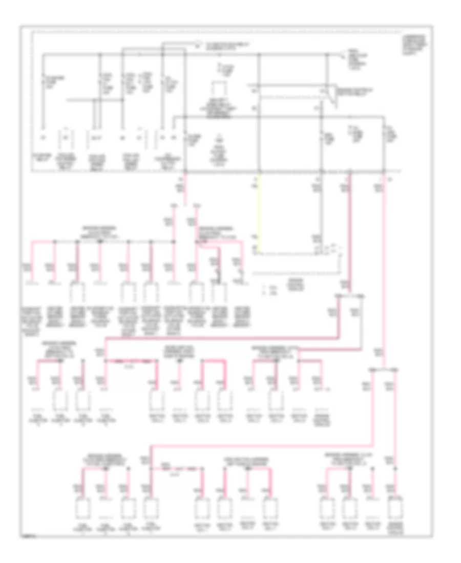
Power Distribution Wiring Diagram (1 of 5) for Chevrolet Camaro SS 2012


List of elements for Power Distribution Wiring Diagram (1 of 5) for Chevrolet Camaro SS 2012:
- (a/t)
- (driver door harness, 8.5 cm from brakeout to x501) j505
- (engine harness, 16.4 cm from breakout to x107) j129
- (engine harness, 5 cm from breakout to heated oxygen sensor bank 1 sensor 1) j115
- (m/t)
- (not used)
- (right front of engine compt) underhood fuse block
- 02 post fuse 10a
- 1 sensor 2) j117
- 3.6l
- 6.2l
- Abs pmp fuse 40a
- Abs valve fuse 25a
- Afl/ahl batt fuse 5a
- Automatic transmission assembly (a/t)
- Battery
- Battery cable junction block
- Battery fuse block (at battery)
- Bcm 6 fuse 20a
- Body control module
- Can vent sol fuse 10a
- Control solenoid valve assembly
- Convertible
- Coupe
- Driver window motor
- Driver window switch
- Electronic brake control module
- Evaporative emission vent solenoid valve
- Front fog lamp relay
- Frt htd seats fuse 25a
- Frt hvac fuse 40a
- Fusible link 2 100a
- Fusible link 3 60a
- Generator
- Head lamp leveling control module (if equipped)
- Headlamp high beam relay
- Headlamp low beam relay
- Heated oxygen sensor bank 1 sensor 2
- Heated oxygen sensor bank 2 sensor 2
- Horn relay
- J305 (body harness, 38 cm from breakout to x306)
- Left rear window motor
- Nca
- Osrvm fuse 7.5a
- Outside rearview mirror switch
- Passenger window motor
- Pwr wdo frt fuse 30a
- Pwr wdo rear fuse 30a
- Rear defogger relay
- Red
- Right rear window motor
- S roof fuse 25a
- Seat heating control module (w/ front seat heater)
- Starter motor
- Sunroof control module (w/ electric sliding sun glass roof)
- Tcm fuse 15a
- To ecm fuse (diagram 2 of 5)
- To instrument panel fuse block (diagram 3 of 5)
- To power- train relay (diagram 2 of 5)
- To splice j409 (diagram 5 of 5)
- Trans- mission control module
- Windshield washer pump relay
- X206
- X208
- X210
- X307
- X350
- X500
- X600
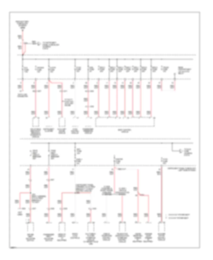
Power Distribution Wiring Diagram (2 of 5) for Chevrolet Camaro SS 2012
List of elements for Power Distribution Wiring Diagram (2 of 5) for Chevrolet Camaro SS 2012:
- (engine harness, 3.2 cm from breakout to fuel injector 5) j113
- (engine harness, 3.2 cm from breakout to ignition coil 3) j113
- (engine harness, 3.9 cm from breakout to ignition coil 6) j123
- (engine harness, 6.9 cm from breakout to x161) j119
- (engine harness, 9.4 cm from breakout to x102) j126
- (even ignition harness, right side of engine)
- (odd ignition harness, left side of engine) j142
- 02 pre fuse 10a
- 3.6l
- 6.2l
- A/c compressor clutch relay
- Ac cltch fuse 10a
- Atws fuse 7.5a
- Camshaft position actuator solenoid valve exhaust bank 1
- Camshaft position actuator solenoid valve exhaust bank 2
- Camshaft position actuator solenoid valve intake bank 1
- Camshaft position actuator solenoid valve intake bank 2
- Cool fan hi fuse 30a
- Cool fan low fuse 30a
- Cool fan rly fuse 10a
- Cooling fan high speed relay
- Cooling fan low speed relay
- Cooling fan speed control relay
- Ecm fuse 15a
- Engine control module
- Engine controls ignition relay
- Evaporative emission purge solenoid valve
- From abs pump fuse (diagram 1 of 5)
- From o2 post fuse (diagram 1 of 5)
- Fuel injector
- Heated oxygen sensor bank 1 sensor 1
- Heated oxygen sensor bank 2 sensor 1
- Ignition coil 1
- Ignition coil 2
- Ignition coil 3
- Ignition coil 4
- Ignition coil 5
- Ignition coil 6
- Ignition coil 7
- Ignition coil 8
- Inj even fuse 20a
- Inj odd fuse 20a
- J131
- Nca
- Pnk
- Security siren relay (w/content theft deterrent alarm horn)
- Starter fuse 30a
- Starter relay
- To ignition run relay (diagram 4 of 5)
- Underhood fuse block (right front of engine compt)
- X112
- X113
Power Distribution Wiring Diagram (3 of 5) for Chevrolet Camaro SS 2012
List of elements for Power Distribution Wiring Diagram (3 of 5) for Chevrolet Camaro SS 2012:
- (instrument panel harness, 5.6 cm from breakout to body control module) j208
- (not used)
- Air bag fuse 10a
- Aos fuse 5a
- Auxiliary gauge module
- Bat fuse 30a
- Bcm 1 fuse 20a
- Bcm 2 fuse 20a
- Bcm 3 fuse 30a
- Bcm 4 fuse 30a
- Bcm 5 fuse 25a
- Bcm 7 fuse 20a
- Bcm 8 fuse 30a
- Blower motor control module
- Body control module
- Clstr fuse 10a
- Data link connector
- Disply fuse 10a
- Dlc fuse 7.5a
- Driver seat adjuster switch
- Drvr seat circuit breaker 25a
- From battery fuse block (diagram 1 of 5)
- Garage door opener (if equipped)
- Head-up display (if equipped)
- Hvac control module
- Hvac fuse 15a
- Hvac fuse 40a
- Inflatable restraint sensing & diagnostic module
- Inside rearview mirror (if equipped)
- Instrument cluster
- Instrument panel fuse block (left side of dash)
- J301 (body harness, 27.8 cm from breakout to x307)
- Mobile telephone control module
- Multimedia player interface module (w/ receptacle usb)
- Onstar fuse 7.5a
- Pass seat circuit breaker 25a
- Passenger presence module
- Passenger seat adjuster switch
- Radio/ hvac controls
- Rear compartment lid unlatch relay
- Telematics communication interface control module
- To dlis fuse (diagram 5 of 5)
- To instrument panel fuse block (diagram 4 of 5)
- Trunk fuse 10a
- W/ 6 way power seat
- W/ gps 1 vehicle communication system
- W/ multi- function auxiliary gauge
- W/ sms voice rec & short range wireless interface
- W/o 6 way power seat
- X204
- X207
- X208
- X211
- X225
- X302
- X306
- X307
- X600
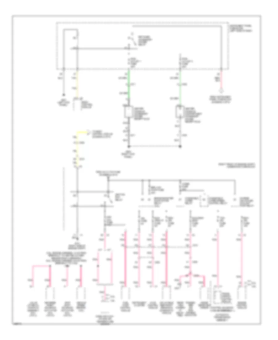
Power Distribution Wiring Diagram (4 of 5) for Chevrolet Camaro SS 2012
List of elements for Power Distribution Wiring Diagram (4 of 5) for Chevrolet Camaro SS 2012:
- (3.6l: engine harness, 10 cm from breakout to heated oxygen sensor bank 2 sensor 2) (6.2l: engine harness, 6.6 cm from breakout to x102) j116
- (right front of engine compt) underhood fuse block
- 3.6l
- 6.2l
- A/t
- Automatic transmission assembly
- Body control module
- Brake booster pump motor relay (3.6l)
- Brk vac pump fuse 20a
- Center console accessory power receptacle
- Center console compartment accessory power receptacle
- Charge air cooler coolant pump relay
- Control solenoid valve assembly
- Ecm/ ign fuse 15a
- Engine control module
- From ac cltch fuse (diagram 2 of 5)
- From instrument panel fuse block (diagram 3 of 5)
- Fuel pump control module
- G101 (right side of engine compt)
- G201 (left kick panel)
- G204 (right kick panel)
- Hvac control module
- Ign fuse 5a
- Ignition run relay
- Inflatable restraint sensing & diagnostic module
- Inside rearview mirror
- Instrument cluster
- Instrument panel fuse block (left side of dash)
- M/t
- Maf/ ccc fuse 7.5a
- Mass air flow/ intake air temperature sensor
- Nca
- Passen- ger air bag disable indicator
- Pnk
- Pwr outlet 1 fuse 20a
- Pwr outlet 2 fuse 20a
- Rear- view camera (if equip- ped)
- Retained accessory power relay
- Reverse inhibit solenoid actuator (6.2l (vin w))
- Run/ crnk ip fuse 5a
- Run/crnk body fuse 10a
- Sdm/ ign fuse 5a
- Skip shift solenoid actuator (6.2l (vin w))
- Tan
- Tcm/ ign fuse 20a
- To body control module (diagram 5 of 5)
- Trans- mission control module
- Valve lifter oil manifold assembly (6.2l (vin j))
- Vehicle speed sensor (3.6l)
- Windshield wiper relay
- Windshield wiper speed control relay
- Wiper fuse 30a
- X204
- X208
- X210
- X211
- X302
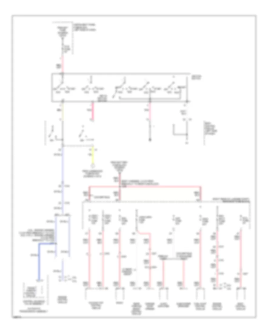
Power Distribution Wiring Diagram (5 of 5) for Chevrolet Camaro SS 2012
List of elements for Power Distribution Wiring Diagram (5 of 5) for Chevrolet Camaro SS 2012:
- (3.6l : engine harness, 7.2 cm from breakout to x102) (6.2l (vin j) : engine harness, 13.2 cm from breakout to x102) j111
- (body harness, 3.8 cm from breakout to rear fuse block) j409
- (right rear of luggage compt) rear body fuse block
- 3.6l
- 6.2l
- A/t
- A13
- Acc
- Amp fuse 30a
- Audio amplifier
- Automatic transmission assembly
- Body control module
- Body control module (left side of dash)
- Control solenoid valve assembly
- Conv/ top 1 fuse 30a
- Conv/ top 2 fuse 10a
- Convertible
- Convertible w/ enhanced audio
- Dlis fuse 5a
- Ecm batt fuse 20a
- Engine control module
- Folding top control module
- From bat fuse (diagram 3 of 5)
- From battery fuse block (diagram 1 of 5)
- From underhood fuse block (diagram 4 of 5)
- Fscm fuse 20a
- Fuel pump control module
- Garage door opener
- Ign
- Ignition switch
- Instrument panel fuse block (left side of dash)
- Key-in ignition switch
- M/t
- Off
- Pnk
- Premium audio
- Radio
- Rdo fuse 20a
- Rear parking assist control module
- Run
- Rvc fuse 5a
- Start
- Subwoofer speaker
- Trans- mission control module
- Ugdo/urpa fuse 7.5a
- W/ rear parking assist
- X102
- X103
- X104
- X204
- X207
- X208
- X210
- X403

 Čeština
 Dansk
Dansk Deutsch
 Ελληνικά
 English
 English
 Español
 Suomi
Suomi Français
 עברית
עברית Hrvatski
 Magyar
 Italiano
 日本語
日本語 한국어
한국어 Nederlands
 Polski
 Português
 Português
 Română
 Русский
 Slovenčina
 Slovenščina
 Svenska
 Türkçe
 中文 (中国)