SHIFT INTERLOCK
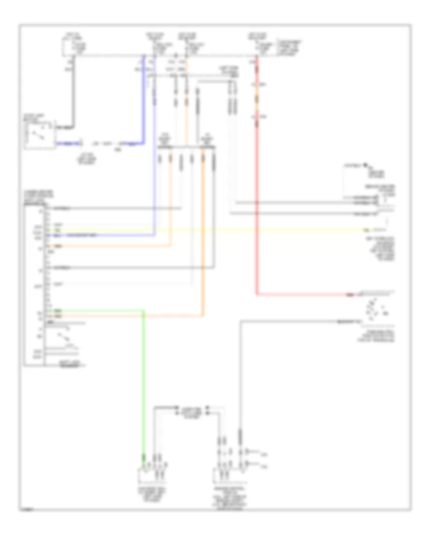
Shift Interlock Wiring Diagram, Except Hybrid for Toyota Camry LE 2011

List of elements for Shift Interlock Wiring Diagram, Except Hybrid for Toyota Camry LE 2011:
- (behind center of dash) j/c e49
- (left side of dash) j/b 3
- (under center floor console) shift lock control ecu
- (w/o smart key)
- 2.5l
- 3.5l
- A24
- A55
- Acc
- Ae2
- C24
- C55
- Ca2
- Canh
- Canl
- Computer data lines system
- E2 (center of dash)
- E32
- E57
- Ea1
- Ecu acc fuse 7.5a
- Ecu ig 2 fuse 7.5a
- Engine control module (2.5l: left side of engine compt) (3.5l: behind right side of dash)
- F15
- F19
- Gauge 1 fuse 10a
- H16
- Hot at all times
- Hot in on or acc
- Hot in on or start
- Instrument panel j/b (left side of dash)
- J/c a42 (left side of dash)
- K11
- Key interlock solenoid (w/o smart key system) (left side of dash)
- Kls+
- L11
- Main body ecu (w/ smart key) (left side of dash)
- Park/neutral position switch (top of transaxle)
- Red
- Shift lock solenoid
- Sls+
- Sls-
- Stop fuse 10a
- Stop lamp switch
- Stp
- W/ smart key system
- W/o smart key system
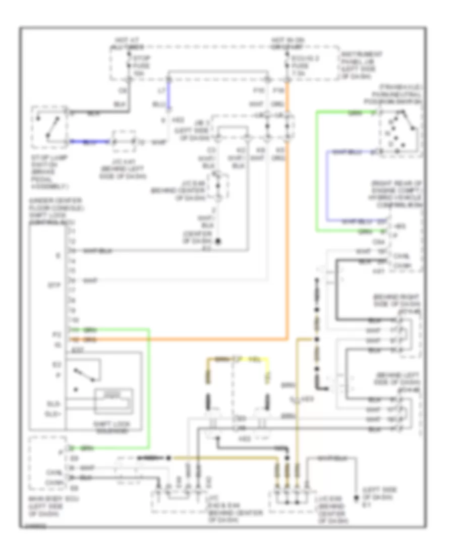
Shift Interlock Wiring Diagram, Hybrid for Toyota Camry LE 2011
List of elements for Shift Interlock Wiring Diagram, Hybrid for Toyota Camry LE 2011:
- (behind left side of dash) j/c a42
- (behind right side of dash) j/c a40
- (center of dash) e2
- (left side of dash) e1
- (right rear of engine compt) hybrid vehicle control ecu
- (transaxle) park/neutral position switch
- (under center floor console) shift lock control ecu
- +bs
- A61
- Ae2
- Ae6
- C64
- Canh
- Canl
- E42 j/c e42 & e44 (behind center of dash)
- E44
- E57
- Ecu ig 2 fuse 7.5a
- F15
- F19
- Hot at all times
- Hot in on or start
- Instrument panel j/b (left side of dash)
- J/b 3 (left side of dash)
- J/c a41 (behind left side of dash)
- J/c e49 (behind center of dash)
- J/c e69 (behind center of dash)
- Main body ecu (left side of dash)
- Nca
- Shift lock solenoid
- Sls+
- Sls-
- Stop fuse 10a
- Stop lamp switch (brake pedal assembly)
- Stp
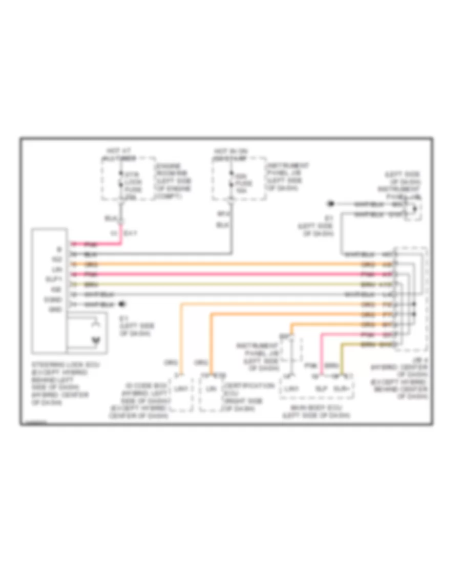
Steering Lock Wiring Diagram for Toyota Camry LE 2011
List of elements for Steering Lock Wiring Diagram for Toyota Camry LE 2011:
- (left side of dash) instrument panel j/b
- A10
- Certification ecu (right side of dash)
- E1 (left side of dash)
- E58
- Ea1
- Engine room r/b (left side of engine compt)
- G10
- Gnd
- Hot at all times
- Hot in on or start
- Id code box (hybrid: left side of dash) (except hybrid: center of dash)
- Ig2
- Ige
- Ign fuse 10a
- Instrument panel j/b (left side of dash)
- J/b 4 (hybrid: center of dash) (except hybrid: behind center of dash)
- Lin
- Lin1
- M14
- Main body ecu (left side of dash)
- Pnk
- Sgnd
- Slp
- Slp1
- Slr+
- Steering lock ecu (except hybrid: behind left side of dash) (hybrid: center of dash)
- Str lock fuse 20a
TRANSMISSIONSHIFT INTERLOCKSTARTING/CHARGINGTRUNK, TAILGATE, FUEL DOORSUPPLEMENTAL RESTRAINTSWARNING SYSTEMSWIPER/WASHERBODY CONTROL MODULESAIR CONDITIONINGCOOLING FANDEFOGGERSELECTRONIC POWER STEERINGANTI-LOCK BRAKESCRUISE CONTROLANTI-THEFTENGINE PERFORMANCECOMPUTER DATA LINESEXTERIOR LIGHTSHEADLIGHTSHORNPOWER DISTRIBUTIONINSTRUMENT CLUSTERNAVIGATIONGROUND DISTRIBUTIONPOWER SEATSINTERIOR LIGHTSPOWER DOOR LOCKSPOWER MIRRORSPOWER TOP/SUNROOFRADIOPOWER WINDOWS