TRANSMISSION
3.4L
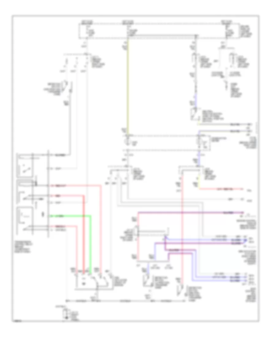
3.4L, 4WD Wiring Diagram for Toyota Tundra SR5 2004
List of elements for 3.4L, 4WD Wiring Diagram for Toyota Tundra SR5 2004:
- (a/t w/ vsc)
- (a/t w/o vsc)
- (a/t)
- (w/ vsc)
- (w/o vsc)
- 4wd
- 4wd fuse 20a
- 4wd ind
- A/t
- A/t p ind
- Abs actuator with ecu (right rear corner of engine compt)
- Acc fuse 15a
- Add actuator (front of engine)
- C11
- C12
- C14
- Combination meter
- Detection switch (4wd position) (transfer case)
- Detection switch (l4 position) (transfer case)
- Detection switch (neutral position) (transfer case)
- Diode (a/t) (behind upper left side of dash)
- Driver side j/b (lower left side of dash)
- Engine control module (behind right side of dash)
- Exi
- Exi4
- G11
- Gauge fuse 10a
- Hot in on or acc
- Hot in on or start
- J/c 10 (behind upper left side of dash)
- J/c 11 (behind upper right side of dash)
- J/c 12 (behind upper right side of dash)
- J/c 13 (right kick panel)
- J/c 28, j/c 29 (behind upper right side of dash)
- J/c 8 (behind upper left side of dash)
- J/c 9 (behind upper left side of dash)
- J28
- J29
- M/t w/ vsc
- M/t w/o vsc
- Neutral position switch (part of park/ neutral position switch)
- Red
- S17
- Skid control ecu (behind center of dash)
- Tfn
- Transmission control relay (behind lower right side of dash)
- W/ door lock ctrl
- W/o door lock ctrl
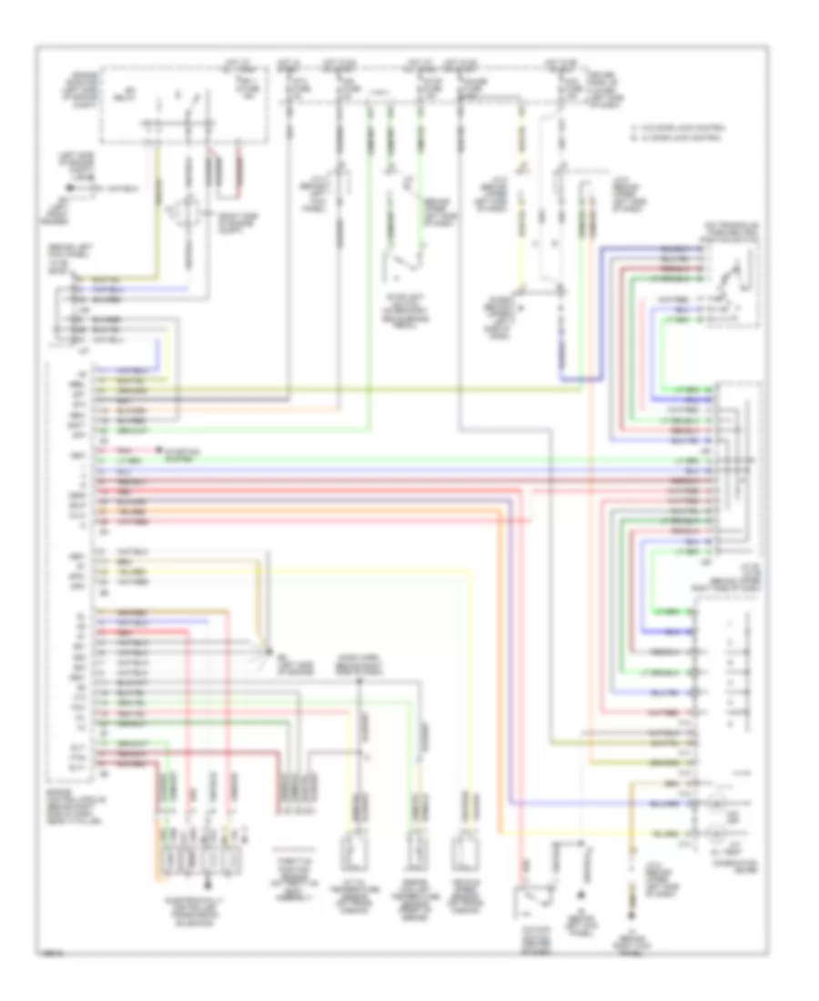
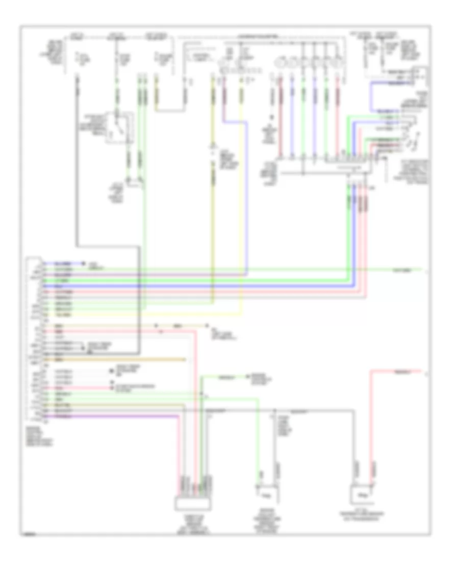
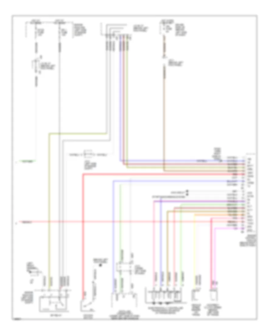
3.4L, A/T Wiring Diagram for Toyota Tundra SR5 2004
List of elements for 3.4L, A/T Wiring Diagram for Toyota Tundra SR5 2004:
- (behind left kick panel) j/c 26, j/c 27
- (behind upper left side of dash)
- (dash harn, behind right side of dash) i3
- (left side of engine compt) j/c 25
- (on transaxle) park/neutral position switch
- (right side of engine compt)
- A/t oil temp
- A/t oil temperature sensor (on trans- mission)
- Acc fuse 15a
- Batt
- C11
- C12
- C13
- C14
- Combination meter
- Diode (behind upper left side of dash)
- Driver side j/b (lower left side of dash)
- E01
- E02
- E03
- Ea (left front fender)
- Ed (left side of engine)
- Efi 1 fuse 15a
- Efi relay
- Electronically controlled transmission solenoids
- Engine control module (behind right side of dash, near "a" pillar)
- Engine coolant temperature sensor (front of engine)
- Engine room r/b (left side of engine compt)
- F11
- G11
- Gauge fuse 10a
- Hot at all times
- Hot in on or acc
- Hot in on or start
- Hot in start
- Ie (behind left kick panel)
- Ign fuse 5a
- Igsw
- Ih (behind right kick panel)
- J/c
- J/c 28, j/c 29 (behind upper right side of dash)
- J/c 4 (behind left kick panel)
- J/c 8 (behind upper left side of dash)
- J/c 9 (behind upper left side of dash)
- J26
- J27
- J28
- J29
- Me01
- Mrel
- No. 1
- No. 2
- No. 3
- Nsw
- O/d main switch (center of dash)
- O/d off
- Odlp
- Odms
- Oil
- Oilw
- Pnk
- Red
- Slt
- Slt+
- Slt-
- Sp1
- Sp2+
- Sp2-
- Sta
- Sta fuse 5a
- Starting system
- Stop fuse 15a
- Stoplight switch (on bracket, above brake pedal)
- Stp
- Throttle position sensor (on throttle body assembly)
- Thw
- Vehicle speed sensor (on trans- mission)
- Vta
- Vta2
- W/ door lock control
- W/o door lock control
4.7L
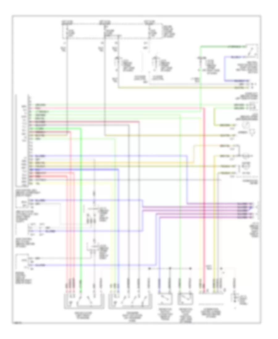
4.7L, 4WD Wiring Diagram, Access/Standard Cab for Toyota Tundra SR5 2004
List of elements for 4.7L, 4WD Wiring Diagram, Access/Standard Cab for Toyota Tundra SR5 2004:
- (a/t)
- (behind upper right side of dash)
- (m/t)
- 2-4
- 4hi ind
- 4lo ind
- 4wd
- 4wd control ecu (behind lower right side of dash)
- 4wd fuse 20a
- Abs actuator with ecu (w/o vsc) (right rear of engine compt)
- Acc fuse 15a
- Add
- Add actuator (left front of engine)
- C11
- C12
- C13
- C14
- Combination meter
- Detection switch (4wd position) (left side of trans)
- Detection switch (l4 position) (rear of trans)
- Diode (a/t) (behind upper left side of dash)
- Dl1
- Dl2
- Dm1
- Dm2
- Driver side j/b (lower left side of dash)
- Engine control module (behind right side of dash)
- Exi
- Exi4
- G j28
- G j29
- G11
- Gauge fuse 10a
- Gnd
- H-l
- Hot in on or acc
- Hot in on or start
- I24
- Ind1
- Ind2
- Integration control & panel (behind center of dash)
- J/c 10 (behind upper left side of dash)
- J/c 12
- J/c 13 (right kick panel)
- J/c 20 (behind upper right side of dash)
- J/c 28, j/c 29 (behind upper right side of dash)
- J/c 8 (behind upper left side of dash)
- J/c 9 (behind upper left side of dash)
- Neutral position switch (part of park/ neutral position switch)
- Pnk
- Red
- S17
- Skid control ecu (w/vsc) (behind center of dash)
- Spd
- Speedo
- Tl1
- Tl2
- Tl3
- Tm1
- Tm2
- Transfer shift actuator (on transfer case)
- W/ door lock ctrl
- W/o door lock ctrl
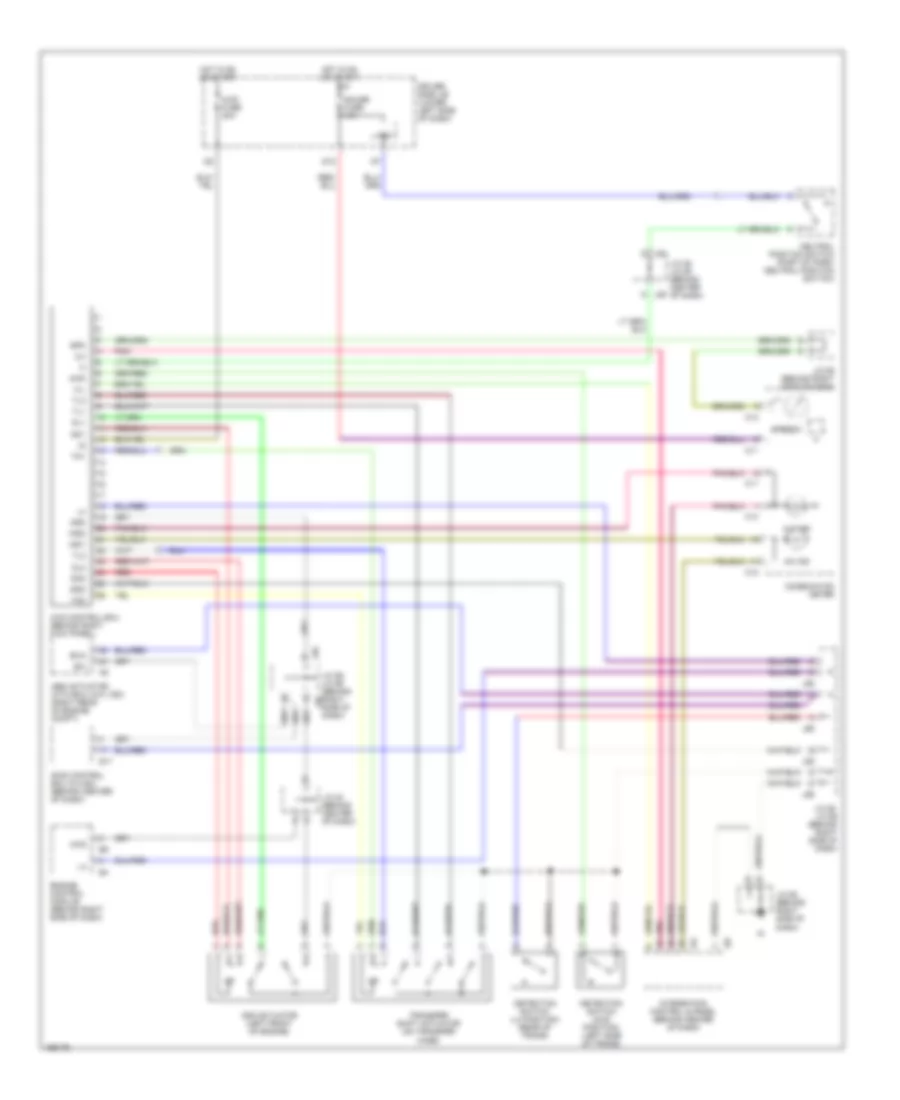
4.7L, 4WD Wiring Diagram, Double Cab for Toyota Tundra SR5 2004
List of elements for 4.7L, 4WD Wiring Diagram, Double Cab for Toyota Tundra SR5 2004:
- 2-4
- 4hi ind
- 4lo ind
- 4wd
- 4wd control ecu (behind right kick panel)
- 4wd fuse 20a
- Abs actuator with ecu (w/o vsc) (right rear of engine compt)
- Add
- Add actuator (left front of engine)
- C11
- C12
- C13
- C14
- Combination meter
- D12
- Detection switch (4wd position) (left side of trans)
- Detection switch (l4 position) (rear of trans)
- Dl1
- Dl2
- Dm1
- Dm2
- Driver side j/b (lower left side of dash)
- Engine control module (behind right side of dash)
- Exi
- Exi4
- G j28
- G j29
- Gauge fuse 15a
- Gnd
- H-l
- Hot in on or start
- I24
- I25
- Ind1
- Ind2
- Integration control & panel (behind center of dash)
- Ipo
- J/c 20 (behind center of dash)
- J/c 28, j/c 29 (behind center of dash)
- J/c 55 (behind right side of dash)
- J/c 55, j/c 56 (behind right side of dash)
- J/c 58 (behind right side of dash)
- J55
- J56
- Neutral position switch (part of park/ neutral position switch)
- Pnk
- Red
- S17
- Skid control ecu (w/vsc) (behind center of dash)
- Spd
- Speedo
- Tl1
- Tl2
- Tl3
- Tm1
- Tm2
- Transfer shift actuator (on transfer case)
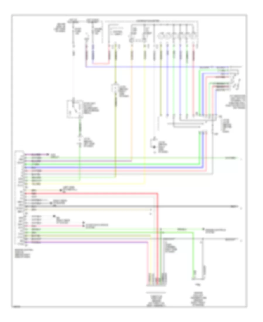
4.7L, A/T Wiring Diagram, Access/Standard Cab (1 of 2) for Toyota Tundra SR5 2004
List of elements for 4.7L, A/T Wiring Diagram, Access/Standard Cab (1 of 2) for Toyota Tundra SR5 2004:
- (dash harn right side of dash)
- (on transmission)
- (right rear of engine) eb
- +bm
- 4wd circuit
- A/t indicator light switch (integral to park/neutral position switch) (on trans)
- A/t oil temp
- A/t oil temperature sensor
- Acc fuse 15a
- C j/c 10 (upper left side of dash)
- C11
- C13
- C14
- Combination meter
- Control unit
- Diode (a/t) (upper left side of dash)
- Driver side j/b (behind left side of dash)
- Driver side j/b (behind lower left side of dash)
- E01
- E02
- E03
- Ec (left side of firewall)
- Engine control module (behind right side of dash)
- Engine controls system
- Engine coolant temperature sensor (right front of engine)
- G11
- Gauge fuse 10a
- Ge01
- Hot at all times
- Hot in run or acc
- Hot in run or start
- Hot in start
- Ie (behind left kick panel)
- J/c 28, j/c 29 (behind center of dash)
- J/c 9 (behind upper left side of dash)
- J28
- J29
- Me01
- Nsw
- O/d off ind
- Odlp
- Oilw
- Pnk
- Red
- Spd
- Sta
- Sta fuse 5a
- Starting/charging system
- Stop fuse 15a
- Stoplight switch (on bracket, above brake pedal)
- Stp
- Stsw
- Throttle position sensor (on throttle body assembly)
- Thw
- Vta1
- Vta2
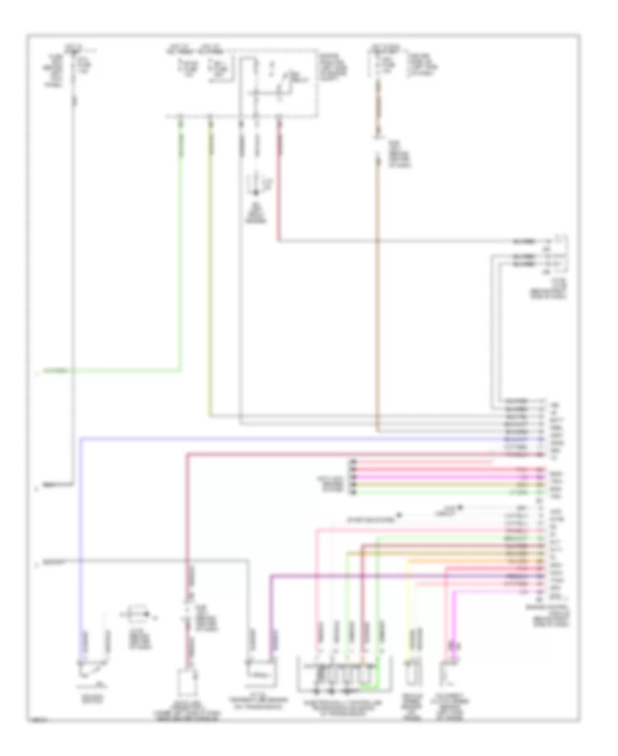
4.7L, A/T Wiring Diagram, Access/Standard Cab (2 of 2) for Toyota Tundra SR5 2004
List of elements for 4.7L, A/T Wiring Diagram, Access/Standard Cab (2 of 2) for Toyota Tundra SR5 2004:
- (behind left kick panel) ie
- (dash harn right side of dash) i5
- (left front fender) ea
- +b2
- 4wd
- 4wd circuit
- Batt
- Data link connector 3 (under left side of dash, near center console)
- Driver side j/b (behind left side of dash)
- Efi 1 fuse 15a
- Efi relay
- Electronically controlled transmission solenoid (in transmission)
- Engine control module (behind right side of dash)
- Engine room r/b (left side of engine compt)
- Etcs fuse 10a
- F11
- Hot at all times
- Hot in run or start
- Ign fuse 5a
- Igsw
- J/c
- J/c 2 (left side of engine compt)
- J/c 26, 27 (behind left kick panel)
- J/c 4 (behind left kick panel)
- J/c 5 (upper left side of dash)
- J26
- J26 j/c 26, 27 (behind left kick panel)
- J27
- Mrel
- Nco+
- Nco-
- O/d direct clutch speed sensor (left side of trans)
- O/d main switch
- Odms
- Pnk
- Red
- Sil
- Slt
- Slt+
- Slt-
- Sp2+
- Sp2-
- Star
- Starting/charging system
- Thoc
- Vehicle speed sensor (on trans)
- Wfse
4.7L, A/T Wiring Diagram, Double Cab (1 of 2) for Toyota Tundra SR5 2004
List of elements for 4.7L, A/T Wiring Diagram, Double Cab (1 of 2) for Toyota Tundra SR5 2004:
- (left side of firewall) ec
- (right rear of engine) eb
- +bm
- 4wd circuit
- A/t indicator light switch (integral to park/neutral position switch) (on trans)
- A/t oil temp
- C11
- C13
- C14
- Combination meter
- Control unit
- D12
- Driver side j/b (left side of dash)
- E01
- E02
- E03
- Eb (right rear of engine)
- Engine control module (behind right side of dash)
- Engine controls system
- Engine coolant temperature sensor (right front of engine)
- Gauge fuse 15a
- Ge01
- Hot at all times
- Hot in run or start
- I3 (dash harness, right side of dash)
- Ipo
- J/c 28, j/c 29 (behind center of dash)
- J/c 45 (behind right side of dash)
- J/c 48 (behind left side of dash)
- J/c 55 (behind right side of dash)
- J28
- J29
- Me01
- Nsw
- O/d off ind
- Odlp
- Oilw
- Pnk
- Red
- Spd
- Sta
- Starting/charging system
- Stop fuse 15a
- Stoplight switch (on bracket, above brake pedal)
- Stp
- Stsw
- Throttle position sensor (on throttle body assembly)
- Thw
- Vta1
- Vta2
4.7L, A/T Wiring Diagram, Double Cab (2 of 2) for Toyota Tundra SR5 2004
List of elements for 4.7L, A/T Wiring Diagram, Double Cab (2 of 2) for Toyota Tundra SR5 2004:
- (on transmission)
- +b2
- 4wd
- 4wd circuit
- A/t oil temperature sensor
- Anti-lock brakes system
- Batt
- Data link connector 3 (under left side of dash, near center console)
- Driver side j/b (left side of dash)
- E17
- Ea (left front fender)
- Efi 1 fuse 20a
- Efi relay
- Electronically controlled transmission solenoid (in transmission)
- Eng+
- Eng-
- Engine control module (behind right side of dash)
- Engine room r/b (left side of engine compt)
- Etcs fuse 10a
- Fuse box (behind left kick panel)
- Hot at all times
- Hot in run or start
- Hot in start
- Ign1 fuse 10a
- Igsw
- J/c
- J/c 54 (behind center of dash)
- J/c 55, j/c 56 (behind right side of dash)
- J55
- J56
- Mrel
- Nco+
- Nco-
- Neo
- O/d direct clutch speed sensor (left side of trans)
- O/d main switch
- Odms
- Pnk
- Slt
- Slt+
- Slt-
- Sp2+
- Sp2-
- Sta fuse 7.5a
- Star
- Starting system
- Sub j/b 3 (behind center of dash)
- Thoc
- Trc+
- Trc-
- Vehicle speed sensor (on trans)

 Čeština
 Dansk
Dansk Deutsch
 Ελληνικά
 English
 English
 Español
 Suomi
Suomi Français
 עברית
עברית Hrvatski
 Magyar
 Italiano
 日本語
日本語 한국어
한국어 Nederlands
 Polski
 Português
 Português
 Română
 Русский
 Slovenčina
 Slovenščina
 Svenska
 Türkçe
 中文 (中国)