AIR CONDITIONING
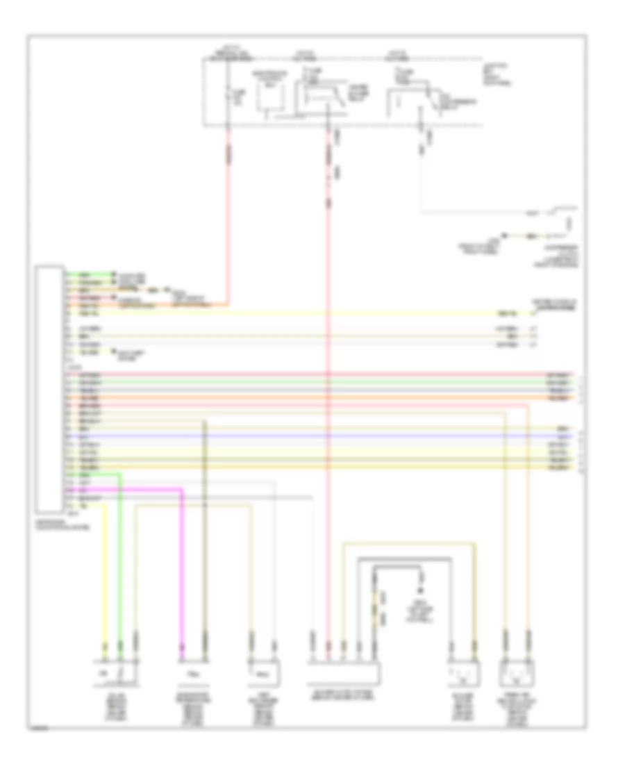
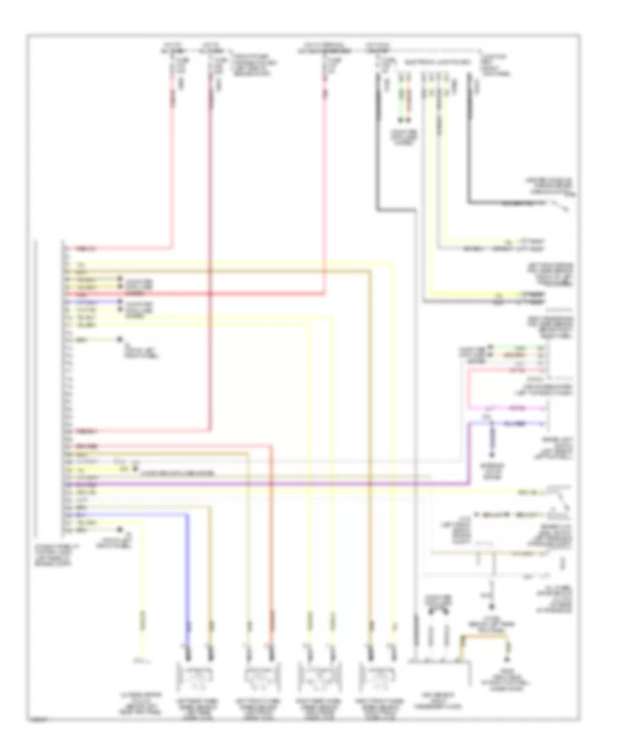
Automatic A/C Wiring Diagram (1 of 2) for MINI Cooper Countryman JCW ALL4 2014
List of elements for Automatic A/C Wiring Diagram (1 of 2) for MINI Cooper Countryman JCW ALL4 2014:
- A/c compressor relay
- Anti-theft system
- Blower motor (behind center of dash)
- Blower output stage (behind center of dash)
- Center console control panel
- Compressor clutch (lower right front of engine)
- Computer data lines system
- Electronics junction box
- Evaporator temperature sensor (behind center of dash)
- Fresh air/ recirculation flap motor (behind center of dash)
- Fuse f20 10a
- Fuse f24 10a
- Fuse f48 30a
- Heat exchanger sensor (behind center of dash)
- Heater blower relay
- Heating/air conditioning system
- Hot at all times
- Hot w/ terminal 30g relay energized
- Interior lights system
- Junction box (right kick panel)
- Red
- Solar sensor (behind center of dash)
- X11007
- X11009
- X165 (front of right front wheel)
- X1879
- X2042 (left side of left footwell)
- X6056
- X610
- X9331
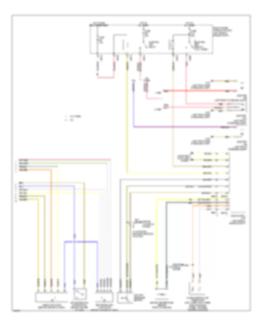
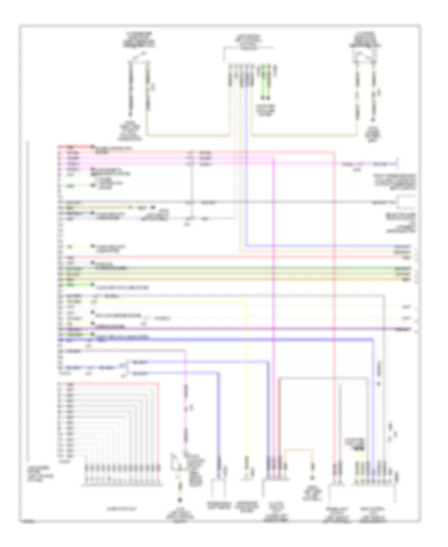
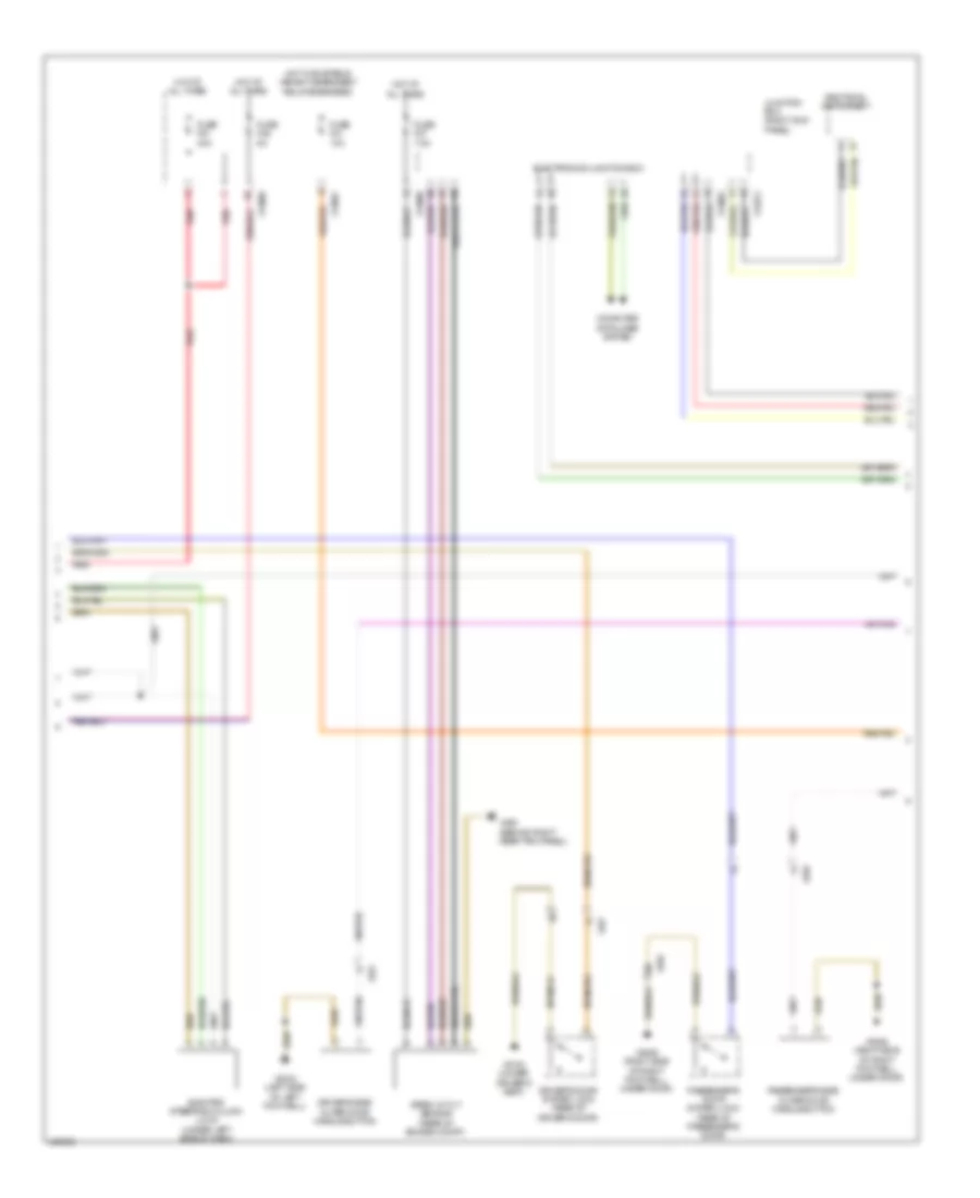
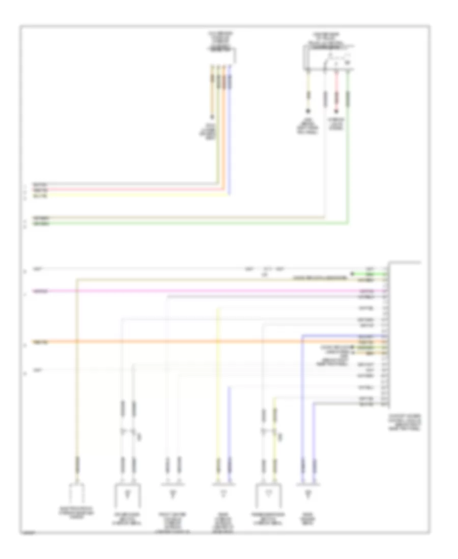
Automatic A/C Wiring Diagram (2 of 2) for MINI Cooper Countryman JCW ALL4 2014
List of elements for Automatic A/C Wiring Diagram (2 of 2) for MINI Cooper Countryman JCW ALL4 2014:
- 1-tier
- 1.6l
- 1.6l turbo
- 2-tier
- Air distribution flap motor (behind center of dash)
- Air distribution microswitch (behind center of dash)
- Characteristic map thermostat (non turbo: right rear side of engine) (turbo: top rear center of engine)
- Computer data lines system
- Coolant pressure sensor
- Dme control unit (left side of engine compt)
- Electric fan (left front of engine compt)
- Electric fan relay
- Electric fan relay 2 (1.6l turbo)
- Engine controls system
- Engine temperature sensor (front of engine)
- Front power distribution box (left side of engine compt)
- Fuse f05 7.5a
- Fuse f08 40a
- Fuse fl9 50a
- Hot at all times
- Hot w/ dme relay energized
- Mixer flap motor (behind center of dash)
- Red
- W/ automatic engine start/stop function
- X175 (left front side of engine compt)
- X4007
- X4010
- X4013
- X4014
- X60004
- X60211
- X60231
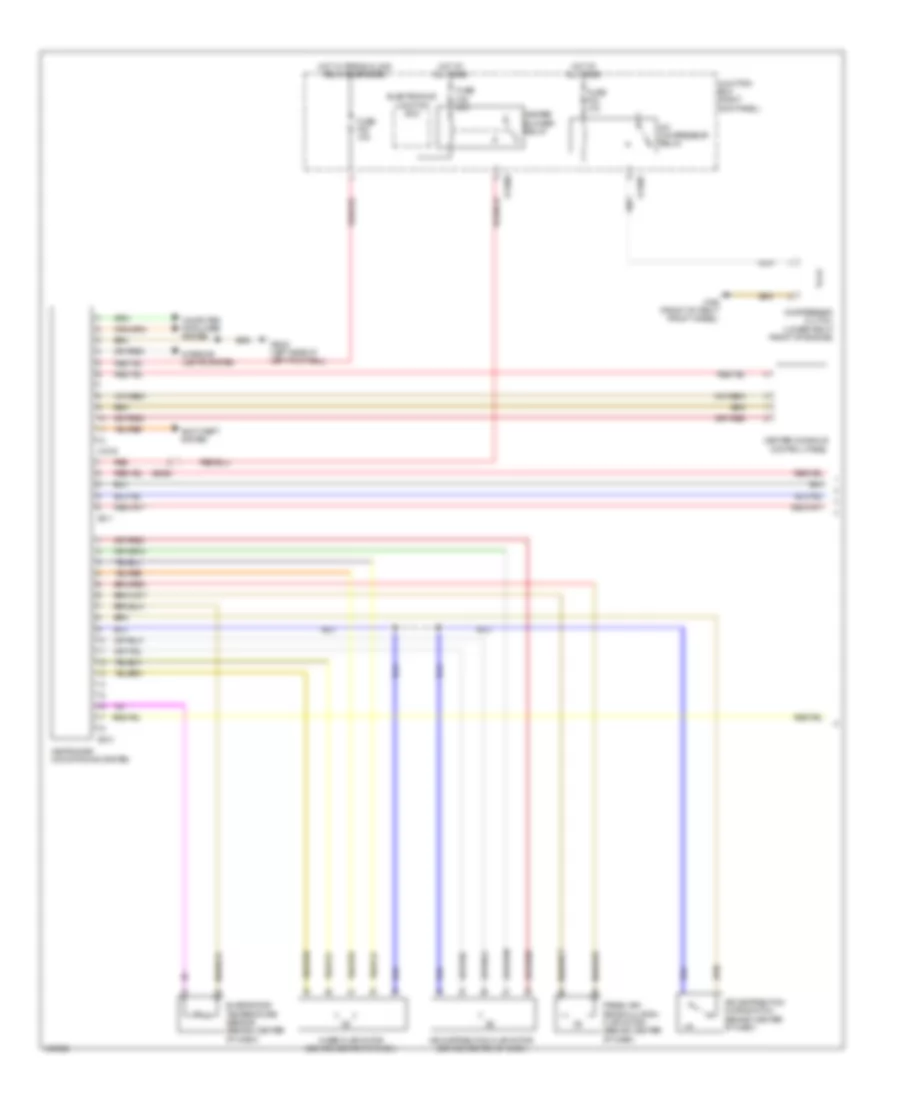
Manual A/C Wiring Diagram (1 of 2) for MINI Cooper Countryman JCW ALL4 2014
List of elements for Manual A/C Wiring Diagram (1 of 2) for MINI Cooper Countryman JCW ALL4 2014:
- A/c compressor relay
- Air distribution flap motor (behind center of dash)
- Air distribution microswitch (behind center of dash)
- Anti-theft system
- Center console control panel
- Compressor clutch (lower right front of engine)
- Computer data lines system
- Electronics junction box
- Evaporator temperature sensor (behind center of dash)
- Fresh air/ recirculation flap motor (behind center of dash)
- Fuse f20 10a
- Fuse f24 10a
- Fuse f48 30a
- Heater blower relay
- Heating/air conditioning system
- Hot at all times
- Hot w/ terminal 30g relay energized
- Interior lights system
- Junction box (right kick panel)
- Mixer flap motor (behind center of dash)
- Red
- X11007
- X11009
- X165 (front of right front wheel)
- X1879
- X2042 (left side of left footwell)
- X6056
- X610
- X611
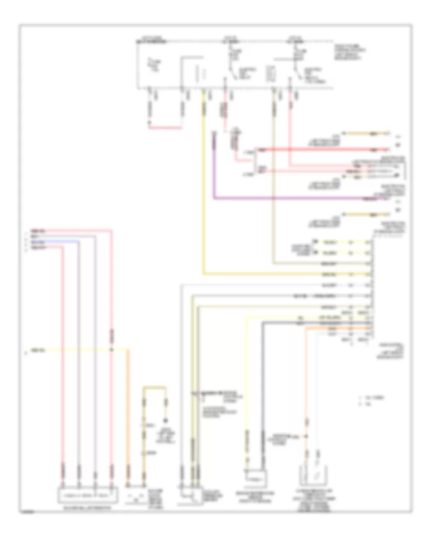
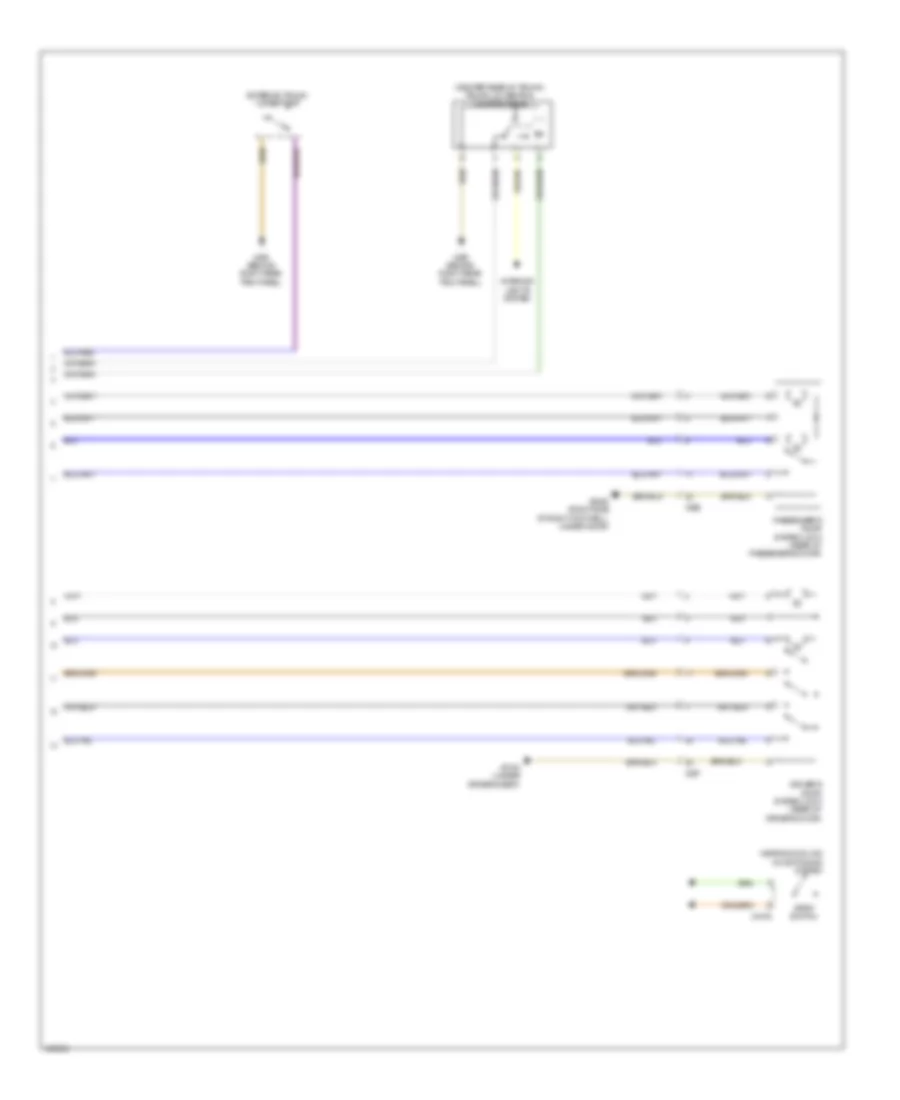
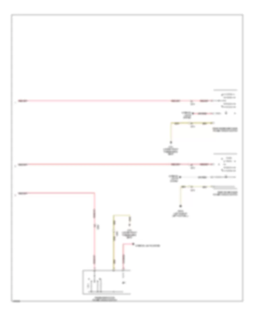
Manual A/C Wiring Diagram (2 of 2) for MINI Cooper Countryman JCW ALL4 2014
List of elements for Manual A/C Wiring Diagram (2 of 2) for MINI Cooper Countryman JCW ALL4 2014:
- 1-tier
- 1.6l
- 1.6l turbo
- 2-tier
- Blower ballast resistor
- Blower motor (behind center of dash)
- Characteristic map thermostat (non turbo: right rear side of engine) (turbo: top rear center of engine)
- Computer data lines system
- Coolant pressure sensor
- Dme control unit (left side of engine compt)
- Electric fan (left front of engine compt)
- Electric fan relay
- Electric fan relay 2 (1.6l turbo)
- Engine controls system
- Engine temperature sensor (front of engine)
- Front power distribution box (left side of engine compt)
- Fuse f05 7.5a
- Fuse f08 40a
- Fuse fl9 50a
- Hot at all times
- Hot w/ dme relay energized
- Red
- W/ automatic engine start stop function
- X175 (left front side of engine compt)
- X2042 (left side of left footwell)
- X4007
- X4010
- X4013
- X4014
- X60004
- X60211
- X60231
- X6056
- X9331
ANTI-LOCK BRAKES
Anti-lock Brakes Wiring Diagram for MINI Cooper Countryman JCW ALL4 2014
List of elements for Anti-lock Brakes Wiring Diagram for MINI Cooper Countryman JCW ALL4 2014:
- (center console) parking brake warning switch
- All-wheel drive vehicle clutch (on rear of transaxle)
- Brake fluid level switch (left rear side of engine compt)
- Brake light switch (left side of left footwell)
- Car access system (left top side of dash)
- Computer data lines system
- Dsc sensor (right passenger floor)
- Dynamic stability control (dsc) (left rear of engine compt)
- Electronic junction box
- Exterior lights system
- Front power distribution box (left side of engine compt)
- Fuse f06 25a
- Fuse f18 5a
- Fuse f35 5a
- Fuse fl6 40a
- Hot at all times
- Hot in on or start
- Hot w/ terminal 30g relay energized
- Junction box (right kick panel)
- Left front brake pad wear sensor (front of left front wheel)
- Left front wheel speed sensor (left front wheel hub)
- Left rear wheel speed sensor (left rear wheel hub)
- Nca
- Outside mirror fold-in (behind left rear trim panel)
- Red
- Right front wheel speed sensor (right front wheel hub)
- Right rear brake pad wear sensor (behind right rear wheel)
- Right rear wheel speed sensor (right rear wheel hub)
- X10318
- X11002
- X1108
- X13795 (behind left rear trim panel)
- X14272
- X15
- X175 (left front side of engine compt)
- X2846 (right side of right footwell, under door)
- X4 (top of left front wheel)
- X4010
- X4013
ANTI-THEFT
Access/Start Wiring Diagram (1 of 3) for MINI Cooper Countryman JCW ALL4 2014
List of elements for Access/Start Wiring Diagram (1 of 3) for MINI Cooper Countryman JCW ALL4 2014:
- (in driver rear door) rear driver side system lock
- (in passenger rear door) rear passenger side system lock
- (left side of left footwell) footwell module
- A/t
- Anti-lock brakes system
- Brake light switch (left side of left footwell)
- Car access system (left top side of dash)
- Clutch module (m/t) (under left side of dash)
- Computer data lines system
- Dme control unit (left side of engine compt)
- Front passenger seat occupancy detector (in front passenger's seat cushion)
- Heating/air conditioning system
- Hood contact switch (left rear side of engine compt)
- M/t
- Mirrors system
- Power distribution system
- Red
- Selector lever position switch (a/t) (at base of gear selector)
- Start stop unit
- Starting/ charging system
- Transmission shift device
- X10318
- X11632
- X14027
- X14260
- X14261
- X15
- X175 (left front side of engine compt)
- X1879
- X2042 (left side of left footwell)
- X2184 (under driver's seat)
- X273
- X274
- X279
- X2846 (right side of right footwell, under door)
- X60004
Access/Start Wiring Diagram (2 of 3) for MINI Cooper Countryman JCW ALL4 2014
List of elements for Access/Start Wiring Diagram (2 of 3) for MINI Cooper Countryman JCW ALL4 2014:
- Additional instrument
- Computer data lines system
- Driver's door system lock (rear of driver's door)
- Driver's side outer door handle button
- Electric steering column lock (under left side of dash)
- Electronics junction box
- Fuse f21 10a
- Fuse f27 7.5a
- Fuse f36 5a
- Fuse f51 40a
- Hot at all times
- Hot w/ bi-stable variant dependent relay energized
- Junction box (right kick panel)
- Passenger's door system lock (rear of passenger's door)
- Passenger's side outer door handle button
- Red
- Siren w/ tilt sensor (rear of engine compt)
- X11001
- X11002
- X11006
- X11008
- X14272
- X2042 (left side of left footwell)
- X2184 (under driver's seat)
- X256
- X257
- X2846 (right side of right footwell, under door)
- X490 (behind right rear trim panel)
Access/Start Wiring Diagram (3 of 3) for MINI Cooper Countryman JCW ALL4 2014
List of elements for Access/Start Wiring Diagram (3 of 3) for MINI Cooper Countryman JCW ALL4 2014:
- (center rear of trunk) trunk lid central locking drive
- (in overhead console) interior movement detector
- Comfort access control module (behind right rear trim panel)
- Computer data lines system
- Computer data lines system x490 (behind right rear trim panel)
- Driver's side section interior aerial
- Electrochromic interior rearview mirror
- Front center console interior antenna (center console)
- Interior lights system
- Passenger's side section interior aerial
- Rear fender aerial
- Rear interior antenna (center of rear seat)
- X15
- X2184 (under driver's seat)
- X256
- X257
- X490 (behind right rear trim panel)
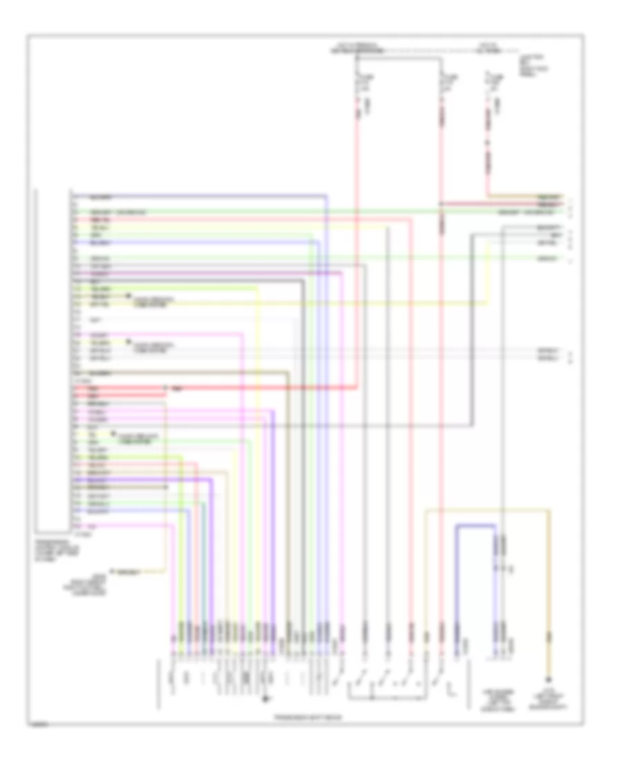
Anti-theft & Central Locking Wiring Diagram (1 of 2) for MINI Cooper Countryman JCW ALL4 2014
List of elements for Anti-theft & Central Locking Wiring Diagram (1 of 2) for MINI Cooper Countryman JCW ALL4 2014:
- (right side of right footwell, under door) x2846
- Can bus high
- Can bus low
- Computer data lines system
- Contact sig
- Electronics junction box
- Footwell module (left side of left footwell)
- Fuel filler flap central locking drive (left side of rear compt)
- Fuse f11 15a
- Fuse f28 15a
- Fuse f4 30a
- Fuse f52 40a
- Fuse f53 40a
- Fuse f8 30a
- Gnd
- Hot at all times
- Interior lights system
- Junction box (right kick panel)
- Lock sig
- Rear driver's side system lock (countryman) (in driver rear door)
- Rear passenger's side system lock (countryman) (in passenger rear door)
- Switch sig
- Term 30
- Unlock sig
- X11002
- X11005
- X11007
- X11010
- X11011
- X14260
- X14261
- X2042 (left side of left footwell)
- X2184 (under driver's seat)
- X273
- X274
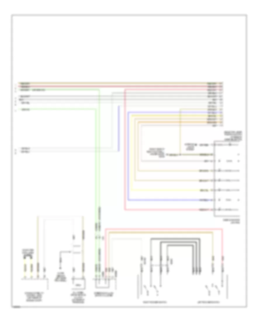
Anti-theft & Central Locking Wiring Diagram (2 of 2) for MINI Cooper Countryman JCW ALL4 2014
List of elements for Anti-theft & Central Locking Wiring Diagram (2 of 2) for MINI Cooper Countryman JCW ALL4 2014:
- (center rear of trunk) trunk lid central locking drive
- Driver's door system lock (rear of driver's door)
- Exterior trunk lid button
- Heating/cooling conditioning system
- Interior lights system
- Passenger's door system lock (rear of passenger's door)
- Strip switch
- X1879
- X2184 (under driver's seat)
- X256
- X257
- X2846 (right side of right footwell, under door)
- X490 (behind right rear trim panel)
BODY CONTROL MODULES
Body Control Modules Wiring Diagram for MINI Cooper Countryman JCW ALL4 2014
List of elements for Body Control Modules Wiring Diagram for MINI Cooper Countryman JCW ALL4 2014:
- (left side of left footwell) footwell module
- (left side of left footwell) x2042
- (not used)
- (under driver's seat) x2184
- Anti-theft & door locks system
- Anti-theft system
- Computer data lines system
- Door locks system
- Exterior lights system
- Footwell module (left side of left footwell)
- Fuse f4 30a
- Fuse f52 40a
- Fuse f53 40a
- Fuse f8 30a
- Headlights & exterior lights systems
- Headlights system
- Hot at all times
- Interior lights system
- Junction box (right kick panel)
- Power windows system
- X11005
- X11007
- X14259
- X14260
- X14261
- X2184 (under driver's seat)
- X257
COMPUTER DATA LINES
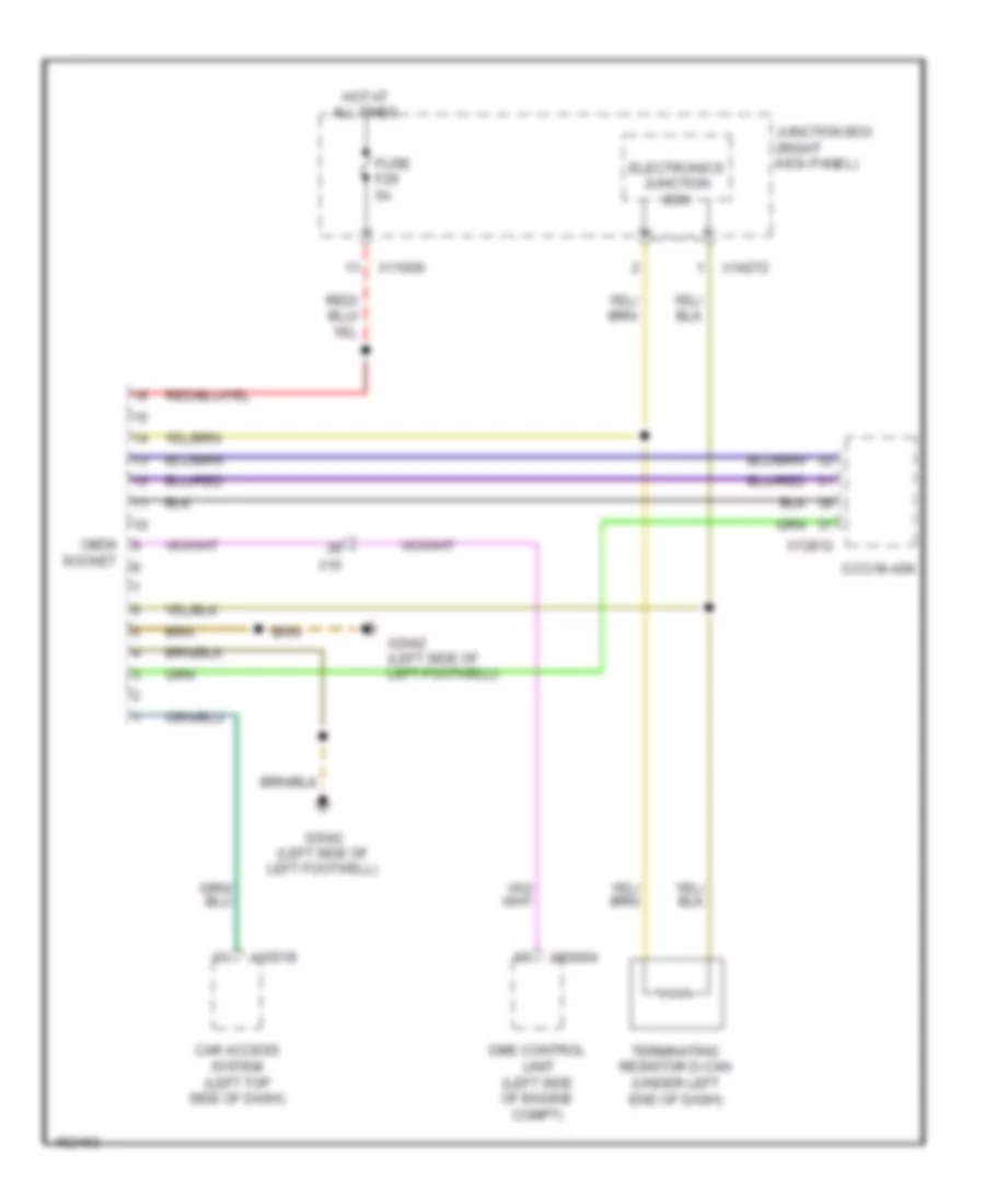
Data Link Connector Wiring Diagram for MINI Cooper Countryman JCW ALL4 2014
List of elements for Data Link Connector Wiring Diagram for MINI Cooper Countryman JCW ALL4 2014:
- Car access system (left top side of dash)
- Ccc/ m-ask
- Dme control unit (left side of engine compt)
- Electronics junction box
- Fuse f29 5a
- Hot at all times
- Junction box (right kick panel)
- Obdii
- Socket
- Terminating resistor d-can (under left end of dash)
- X10318
- X11006
- X13812
- X14272
- X15
- X2042 (left side of left footwell)
- X60004
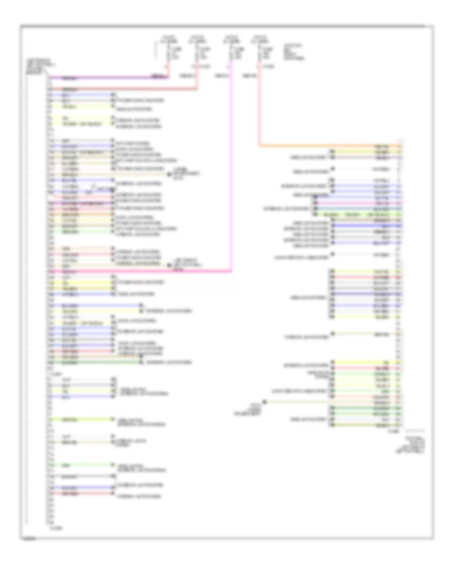
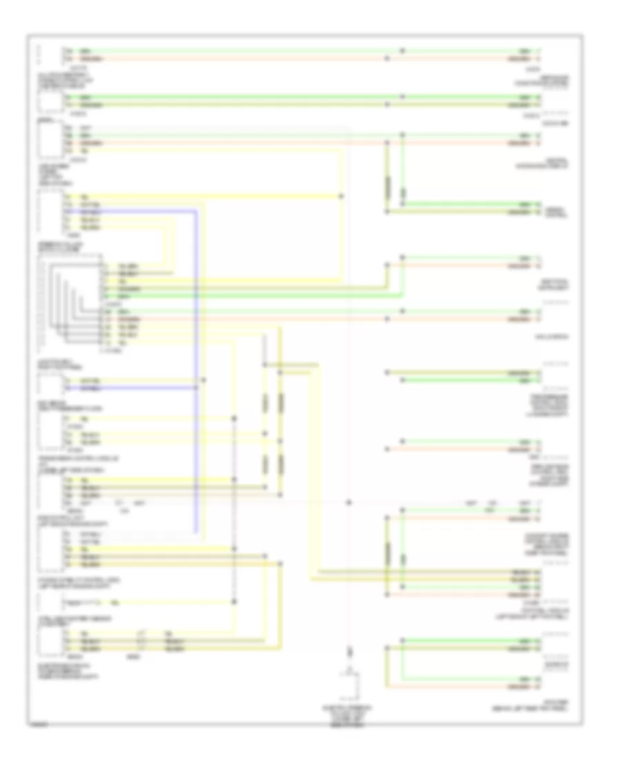
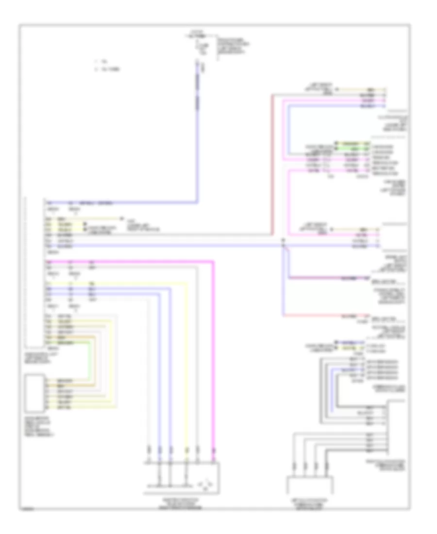
High/Low Bus Wiring Diagram for MINI Cooper Countryman JCW ALL4 2014
List of elements for High/Low Bus Wiring Diagram for MINI Cooper Countryman JCW ALL4 2014:
- Additional instrument
- Amplifier (behind left rear trim panel)
- Car access system (left top side of dash)
- Ccc/m-ask
- Central information display
- Comfort access control module (behind right rear trim panel)
- Dme control unit (left side of engine compt)
- Dsc senor (right passenger floor)
- Dynamic stability control (dsc) (left rear of engine compt)
- Electric steering column lock (under left side of dash)
- Electromechanical power steering (rear of engine compt)
- Footwell module (left side of left footwell)
- Heating/air conditioning system
- Intelligent battery sensor (on battery)
- Junction box (right kick panel)
- Mini joystick
- Mission control
- Multiple restraint system control unit (center console)
- Nca
- Park distance control (pdc) (right side of rear compt)
- Radio
- Steering column switch cluster
- Sunroof
- Tire pressure control (rdc) (right side of luggage compt)
- Transmission control module (a/t) (under left side of dash)
- X10179
- X10318
- X11002
- X11633
- X11634
- X13812
- X14260
- X14272
- X15
- X1879
- X1880
- X300
- X60004
- X60234
- X6060
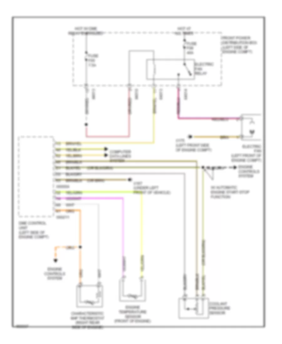
COOLING FAN
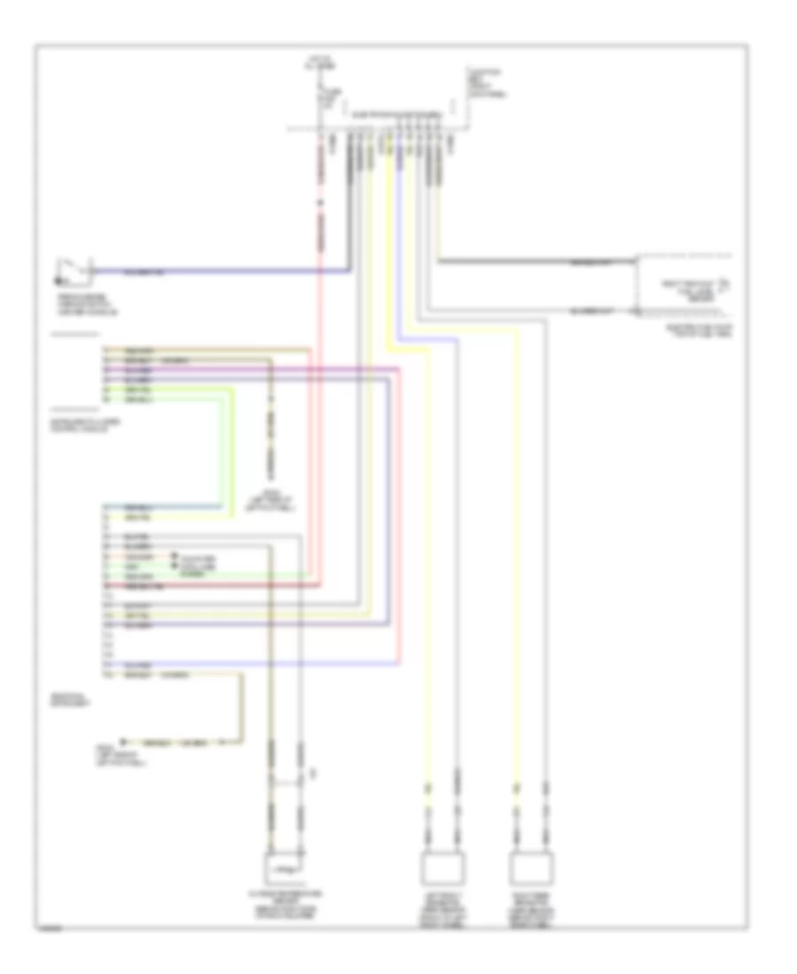
Cooling Fan Wiring Diagram for MINI Cooper Countryman JCW ALL4 2014
List of elements for Cooling Fan Wiring Diagram for MINI Cooper Countryman JCW ALL4 2014:
- Characteristic map thermostat (right rear side of engine)
- Computer data lines system
- Coolant pressure sensor
- Dme control unit (left side of engine compt)
- Electric fan (left front of engine compt)
- Electric fan relay
- Engine controls system
- Engine temperature sensor (front of engine)
- Front power distribution box (left side of engine compt)
- Fuse f05 7.5a
- Fuse f08 40a
- Hot at all times
- Hot w/ dme relay energized
- W/ automatic engine start-stop function
- X167 (under left front of vehicle)
- X175 (left front side of engine compt)
- X4010
- X4013
- X4014
- X60004
- X60211
CRUISE CONTROL
Cruise Control Wiring Diagram for MINI Cooper Countryman JCW ALL4 2014
List of elements for Cruise Control Wiring Diagram for MINI Cooper Countryman JCW ALL4 2014:
- (left side of left footwell) x2042
- 1.6l
- 1.6l turbo
- Accelerator pedal module (part of acceleration pedal assembly)
- Brake light switch (left side of left footwell)
- Brk light sig
- Brk test sig
- Can bus sig
- Car access system (left top side of dash)
- Clutch module (m/t) (under left side of dash)
- Computer data lines system
- Dme control unit (left side of engine compt)
- Dynamic stability control (dsc) (left rear of engine compt)
- Electric throttle valve actuator (right front of engine)
- F-can high
- F-can low
- Footwell module (left side of left footwell)
- Front power distribution box (left side of engine compt)
- Fuse f01 7.5a
- Hot at all times
- Left multi-function steering wheel switch block
- Right multi-function steering wheel switch block
- Spi interface sig
- Steering column switch cluster
- Terminal r sig
- Trans sig
- X01006
- X10318
- X14261
- X15
- X167 (under left front of vehicle)
- X1880
- X4013
- X60004
- X60211
- X60212
- X60231
- X60232
DEFOGGERS
Defoggers Wiring Diagram for MINI Cooper Countryman JCW ALL4 2014
List of elements for Defoggers Wiring Diagram for MINI Cooper Countryman JCW ALL4 2014:
- Computer data lines system
- Driver's side heated water jet
- Driver's side outside mirror
- Front power distribution box (left side of engine compt)
- Fuse f40 30a
- Fuse fl10 50a
- Heating/ air conditioning system
- Hot at all times
- Junction box (right kick panel)
- Junction box electronics
- Left heated windshield
- Nca
- Passenger's side heated water jet
- Passenger's side outside mirror
- Rear window defogger
- Rear window defogger lockout circuit (ground) (left side of rear compt door)
- Rear window defogger lockout circuit (positive) (right side of rear compt door)
- Rear window defroster
- Rear window heated relay
- Red
- Right heated windshield
- W/ rear window aerial
- W/o rear window aerial
- Windshield heater relay (left side of left footwell)
- X11002
- X11007
- X13017
- X13018
- X13443
- X13444
- X13445
- X13446
- X14272
- X151 (under front passenger's seat)
- X1879
- X2042 (left side of left footwell)
- X2184 (under driver's seat)
- X256
- X257
- X4015
- X490 (behind right rear trim panel)
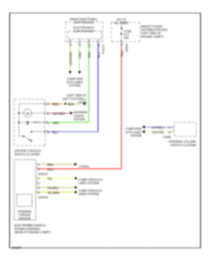
ELECTRONIC POWER STEERING
Electronic Power Steering Wiring Diagram for MINI Cooper Countryman JCW ALL4 2014
List of elements for Electronic Power Steering Wiring Diagram for MINI Cooper Countryman JCW ALL4 2014:
- (left side of left footwell) x2042
- (right kick panel) junction box
- Center console switch cluster
- Computer data lines system
- Electromechanical power steering (rear of engine compt)
- Electronics junction box
- Front power distribution box (left side of engine compt)
- Fuse fl4 80a
- Hot at all times
- Interior lights system
- Red
- Steering column switch cluster
- Steering torque sensor
- X13004
- X14272
- X1880
- X4844
- X60233
- X60234
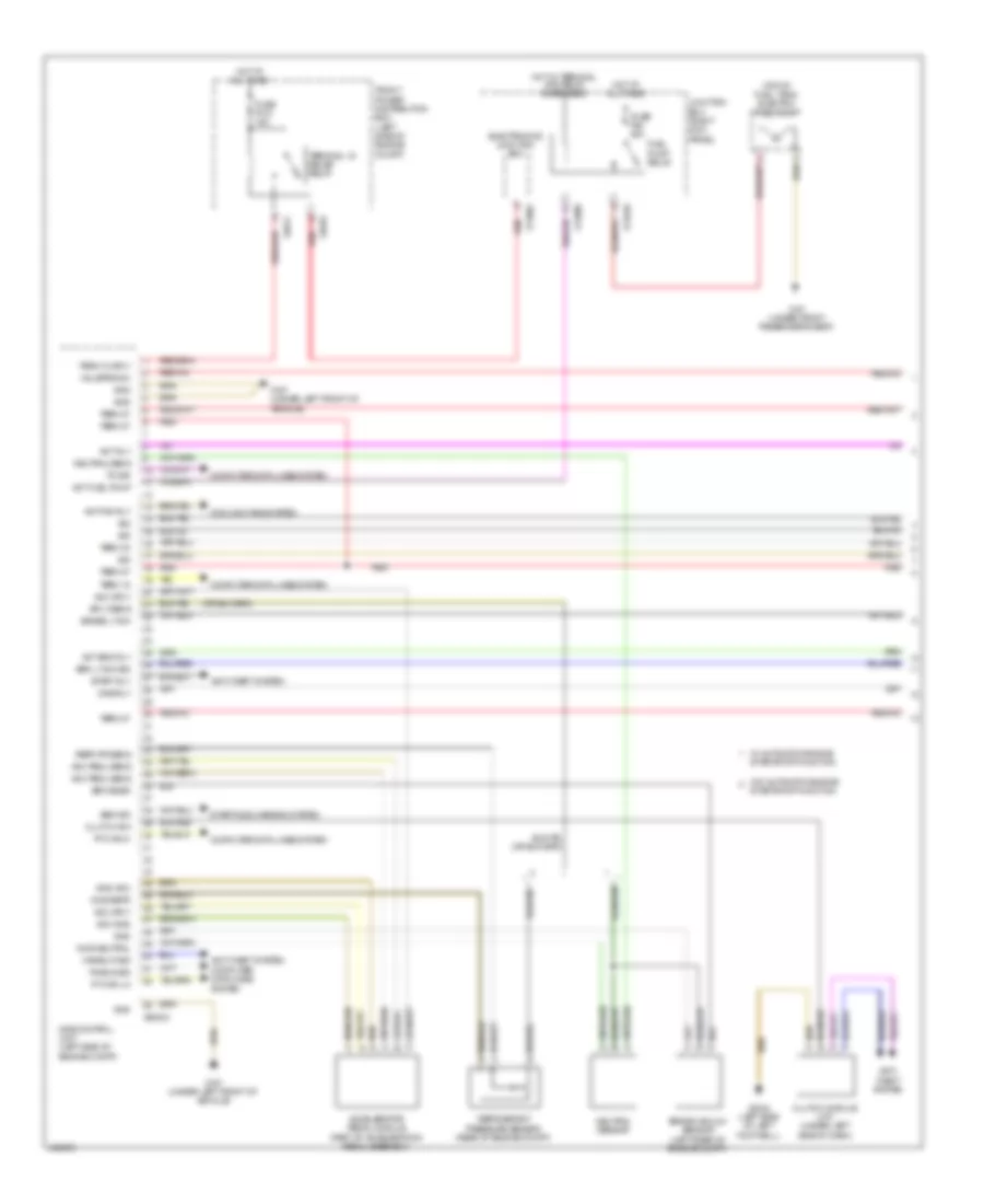
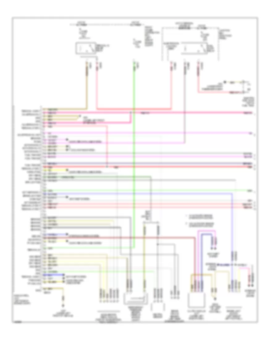
ENGINE PERFORMANCE
1.6L
1.6L, Engine Performance Wiring Diagram (1 of 4) for MINI Cooper Countryman JCW ALL4 2014
List of elements for 1.6L, Engine Performance Wiring Diagram (1 of 4) for MINI Cooper Countryman JCW ALL4 2014:
- (top of fuel tank) electric fuel pump
- Acc gnd
- Acc pedl sens
- Acc sply
- Accelerator pedal module (part of acceleration pedal assembly)
- Act eng rly
- Act fan rly
- Act fuel pump
- Act rly
- Anti- theft system
- Anti-theft system
- Brake lt sw
- Brake vacuum sensor (left rear of engine compt)
- Brk lt sw sig
- Brk snsr
- Bsd sig
- Clutch module (m/t) (under left side of dash)
- Clutch sw
- Computer data lines system
- Cooling fans system
- Dme control unit (left side of engine compt)
- Dme rly
- Electronics junction box
- Front power distribution box (left side of engine compt)
- Fuel pump relay
- Fuse f010 15a
- Fuse f46 20a
- Gnd
- Gnd acc
- Gnd neutral
- Gnd refr
- Hot at all times
- Hot w/ terminal 30g relay energized
- Junction box (right kick panel)
- Neutral sens
- Neutral sensor
- Pa bus sig
- Pt-can hi
- Pt-can lo
- Red
- Refr pr sens
- Refrigerant pressure sensor (rear of engine compt)
- Sig
- Sply sens
- Start rly
- Start/stop function
- Starting/charging system
- Td sig
- Term 15
- Term 15 sply
- Term 30
- Term 87
- Terminal 15 relief relay
- Valvetronic
- W/ automatic engine start/stop function
- W/o automatic engine
- Wake-up sig
- X11002
- X11008
- X11010
- X151 (under front passenger's seat)
- X167 (under left front of vehicle)
- X2042 (left side of left footwell)
- X4010
- X4014
- X60004
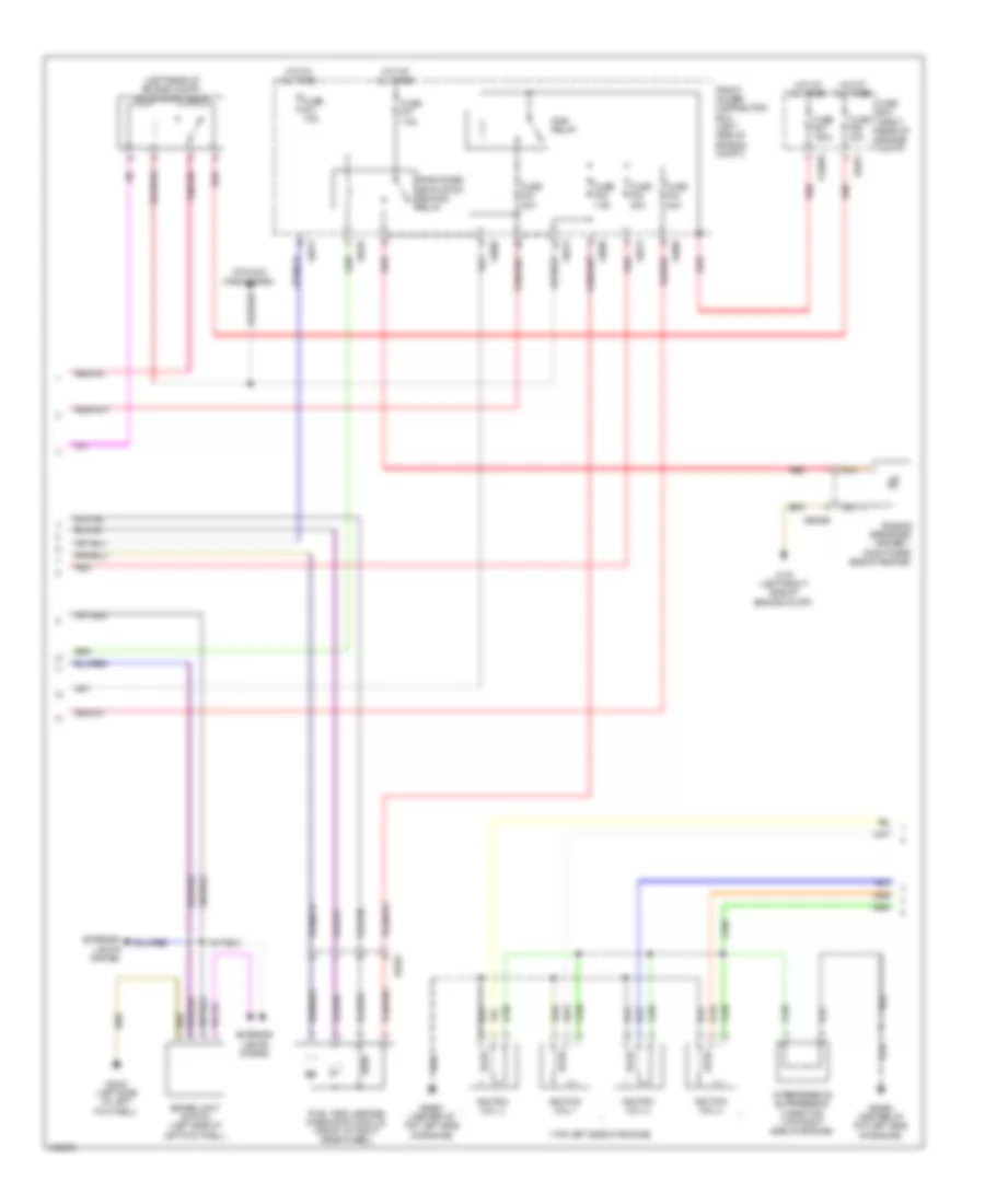
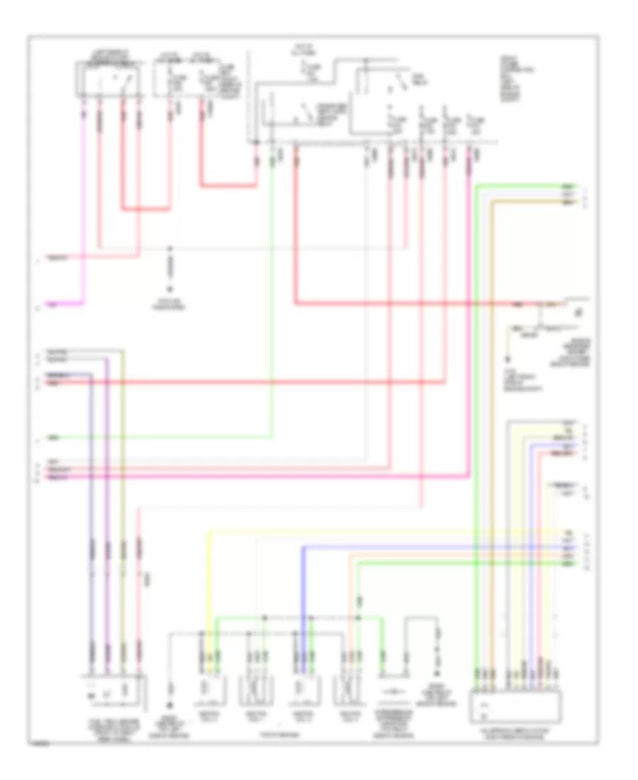
1.6L, Engine Performance Wiring Diagram (2 of 4) for MINI Cooper Countryman JCW ALL4 2014
List of elements for 1.6L, Engine Performance Wiring Diagram (2 of 4) for MINI Cooper Countryman JCW ALL4 2014:
- (left rear of engine compt) valvetronic relay
- (top left side of engine)
- Brake light switch (left side of left footwell)
- Cooling fans system
- Crankcase ventilation heating relay
- Dme relay
- Engine breather heater 1 (right rear side of engine)
- Exterior lights system
- Front power distribution box (left side of engine compt)
- Fuel tank leakage diagnostic module (front of right rear wheel)
- Fuse box (right rear of engine compt)
- Fuse f01 7.5a
- Fuse f02 25a
- Fuse f03 20a
- Fuse f04 20a
- Fuse f05 7.5a
- Fuse f07 7.5a
- Fuse f67 150a
- Fuse f68 40a
- Hot at all times
- Ignition coil 1
- Ignition coil 2
- Ignition coil 3
- Ignition coil 4
- Interference suppression capacitor (top right side of engine)
- Red
- X13020
- X175 (left front side of engine compt)
- X2042 (left side of left footwell)
- X4009
- X4010
- X4013
- X5353
- X6401
- X64561 (center of top left side of engine)
- X65399
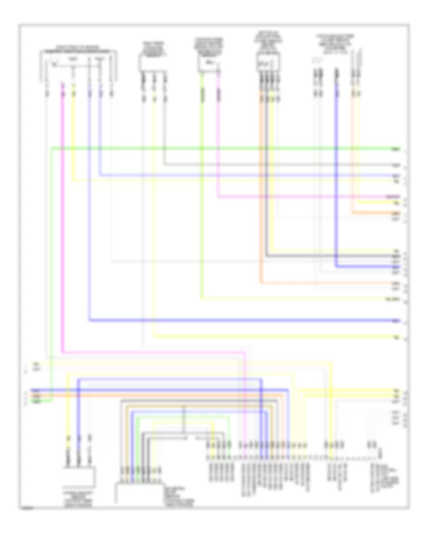
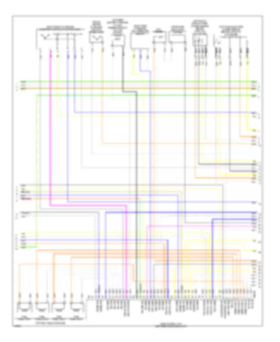
1.6L, Engine Performance Wiring Diagram (3 of 4) for MINI Cooper Countryman JCW ALL4 2014
List of elements for 1.6L, Engine Performance Wiring Diagram (3 of 4) for MINI Cooper Countryman JCW ALL4 2014:
- (bottom of exhaust pipe) oxygen sensor (behind catalytic converter)
- (right front of engine) electric throttle valve actuator
- (right rear of engine) crankshaft sensor
- (top of exhaust pipe) oxygen sensor (before catalytic converter)
- (top right rear side of engine) engine coolant temperature sensor
- Act oil pr ctrl
- Act sol vlve exh
- Act sol vlve int
- Crankshaft sens
- Dme control unit (left side of engine compt)
- Eccentric shaft sensor (top right rear side of engine)
- Elct vlve actutor
- Gnd elct sens
- Gnd int sens
- Hot-film air mas
- Int sply sens
- Intake camshaft sensor (top right rear side of engine)
- Nca
- Shft sens
- Sig exh sens
- Sig ful inj
- Sig ig coil
- Sig int sens
- X60212
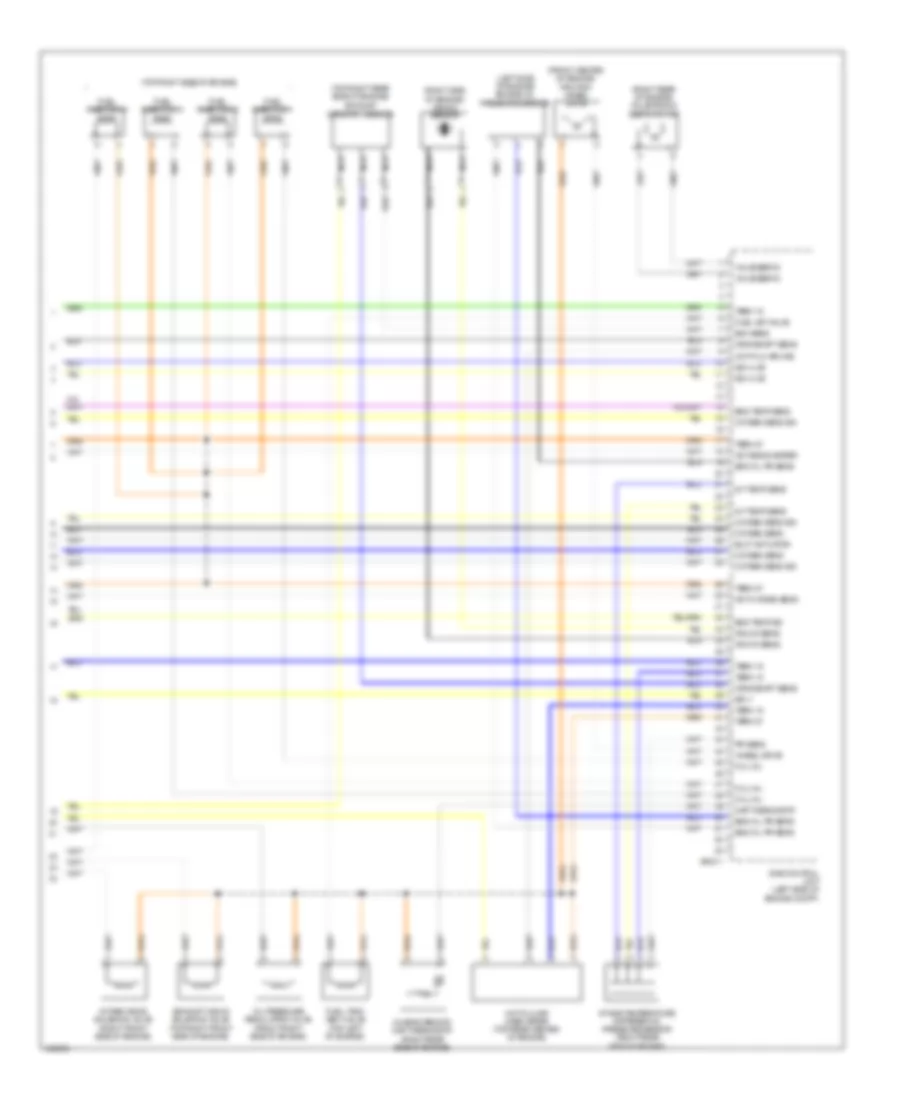
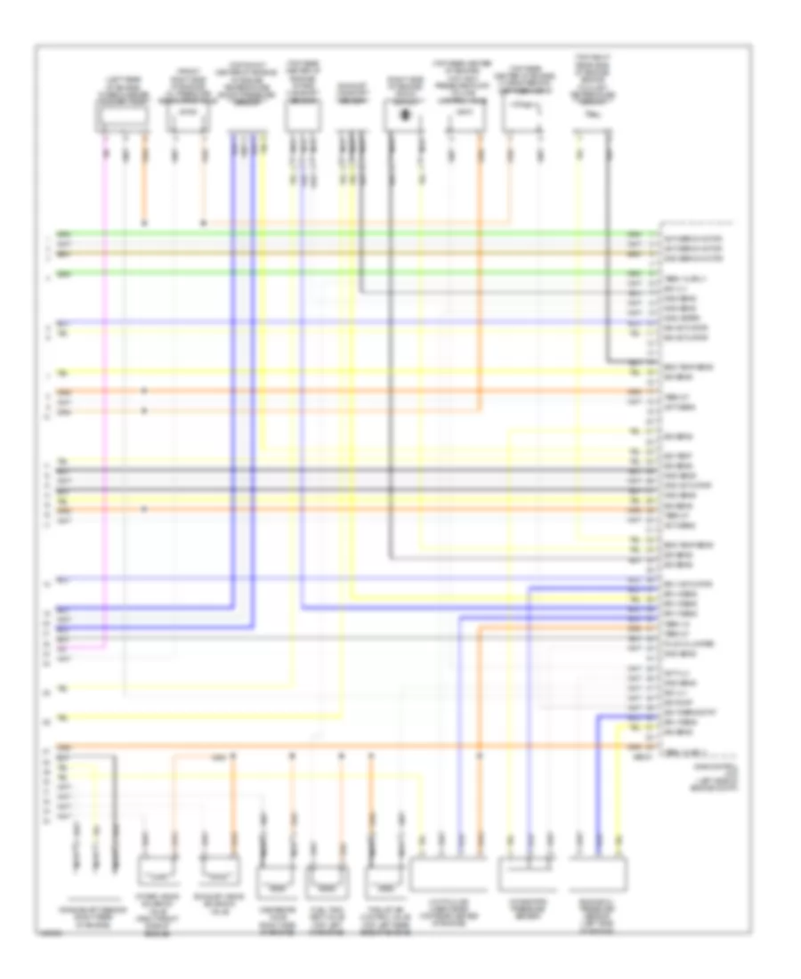
1.6L, Engine Performance Wiring Diagram (4 of 4) for MINI Cooper Countryman JCW ALL4 2014
List of elements for 1.6L, Engine Performance Wiring Diagram (4 of 4) for MINI Cooper Countryman JCW ALL4 2014:
- (front center of engine) friction wheel drive
- (left side of engine) engine oil pressure sensor
- (right rear of engine) valvetronic servo motor
- (right side of engine) knock sensor
- (top right rear side of engine)
- (top right side of engine)
- Act oxygen sens
- Act sens heater
- Characteristic map thermostat (right rear side of engine)
- Crnkshaft sens
- Dme control unit (left side of engine compt)
- Elct actuator
- Eng oil pr sens
- Eng temp sens
- Eng temp sig
- Exh sens
- Exhaust camshaft sensor
- Exhaust vanos solenoid valve (top right front side of engine)
- Fuel injection 1
- Fuel injection 2
- Fuel injection 3
- Fuel injection 4
- Fuel tank vent valve (top left of engine)
- Fuel vet valve
- Fuil inj
- Hot-film air mas
- Hot-film air mass meter (top rear center of engine)
- Int temp sens
- Intake temperature differential pressure sensor (right rear side of engine)
- Intake vanos solenoid valve (right front side of engine)
- Knock sens
- Map thermostat
- Nca
- Oil pressure regulating valve (front right side of engine)
- Oxygen sens
- Oxygen sens sig
- Pr sens
- Sig vlve
- Sply
- Term 15
- Term 87
- Valve servo
- Wheel drive
- X60211
1.6L TURBO
1.6L Turbo, Engine Performance Wiring Diagram (1 of 4) for MINI Cooper Countryman JCW ALL4 2014
List of elements for 1.6L Turbo, Engine Performance Wiring Diagram (1 of 4) for MINI Cooper Countryman JCW ALL4 2014:
- Accelerator pedal module (part of acceleration pedal assembly)
- Act dme relay
- Act heating rly
- Activation rly
- Activation rly 2
- Anti-theft system
- Brake light sig
- Brake light switch (left side of left footwell)
- Brake vacuum sensor (left rear of engine compt)
- Brk light sig
- Bsd sig
- Clutch module (m/t) (under left side of dash)
- Computer data lines system
- Cooling fans system
- Dme control unit (left side of engine compt)
- Electric fuel pump (top of fuel tank)
- Electronics junction box
- Exterior lights system
- Front power distribution box (left side of engine compt)
- Fuel pump relay
- Fuel tank sig
- Fuse f01 7.5a
- Fuse f010 15a
- Fuse f46 20a
- Gnd
- Gnd sens
- Hot at all times
- Hot w/ terminal 30g relay energized
- Junction box (right kick panel)
- Neutral sensor
- Pa bus sig
- Pt can high
- Pt can low
- Red
- Refrigerant pressure sensor (rear of engine compt)
- Sens sig
- Sig switch
- Sply sens
- Start sig
- Starting/charging system
- Td sig
- Terminal 15 relief relay
- Terminal 15 sply
- Terminal 30
- Terminal 87 sply
- Valvetronic rly
- Valvetronic rly act
- W/ automatic engine start/stop function
- W/o automatic engine start/stop function
- Wake up sig
- X11002
- X11008
- X11010
- X151 (under front passenger's seat)
- X167 (under left front of vehicle)
- X2042 (left side of left footwell)
- X4010
- X4013
- X4014
- X60004
1.6L Turbo, Engine Performance Wiring Diagram (2 of 4) for MINI Cooper Countryman JCW ALL4 2014
List of elements for 1.6L Turbo, Engine Performance Wiring Diagram (2 of 4) for MINI Cooper Countryman JCW ALL4 2014:
- (left rear of engine compt) valvetronic relay
- (top of engine)
- Cooling fans system
- Crankcase ventilation heating relay
- Dme relay
- Engine breather heater 1 (right rear side of engine)
- Front power distribution box (left side of engine compt)
- Fuel tank leakage diagnostic module (front of right rear wheel)
- Fuse box (right rear of engine compt)
- Fuse f02 25a
- Fuse f03 20a
- Fuse f04 20a
- Fuse f05 7.5a
- Fuse f07 7.5a
- Fuse f67 150a
- Fuse f68 40a
- Hot at all times
- Ignition coil 1
- Ignition coil 2
- Ignition coil 3
- Ignition coil 4
- Interference suppression capacitor (top right side of engine)
- Red
- Valvetronic servo motor (right rear of engine)
- X13020
- X175 (left front side of engine compt)
- X4009
- X4010
- X4013
- X5353
- X6401
- X64561 (center of top left side of engine)
- X65399
1.6L Turbo, Engine Performance Wiring Diagram (3 of 4) for MINI Cooper Countryman JCW ALL4 2014
List of elements for 1.6L Turbo, Engine Performance Wiring Diagram (3 of 4) for MINI Cooper Countryman JCW ALL4 2014:
- (bottom of exhaust pipe) oxygen sensor behind catalytic converter
- (front center of engine) friction wheel drive
- (right front of engine) electric throttle valve actuator
- (right side of engine) rail pressure sensor
- (top of exhaust pipe) oxygen sensor before catalytic converter
- (top rear center of engine) (w/ high pressure pump) volume control valve
- (top right side of engine)
- Crankcase ventilation bypass
- Dme control unit (left side of engine compt)
- Fuel injection 1
- Fuel injection 2
- Fuel injection 3
- Fuel injection 4
- Gnd actuator
- Gnd friction
- Gnd pump
- Gnd sens
- Ign coil 1 sig
- Ign coil 2 sig
- Ign coil 3 sig
- Ign coil 4 sig
- Inj 1 sig
- Inj 2 sig
- Inj 3 sig
- Inj 4 sig
- Nca
- Pvc heater
- Sig meter
- Sig motor
- Sig oil press
- Sig sens
- Sig vlv
- Sply motor
- Sply sens
- Term 15 sply
- Vlv acti
- Vlvetronic gnd
- Vlvetronic sig
- X60232
1.6L Turbo, Engine Performance Wiring Diagram (4 of 4) for MINI Cooper Countryman JCW ALL4 2014
List of elements for 1.6L Turbo, Engine Performance Wiring Diagram (4 of 4) for MINI Cooper Countryman JCW ALL4 2014:
- (front right side of engine) oil pressure regulating valve
- (left rear of engine) turbocharger coolant pump
- (right side of engine) knock sensor
- (top front center of engine) intake air temperature/ boost pressure sensor
- (top rear center of engine) (w/o high pressure pump) volume control valve
- (top rear center of engine) characteristic map thermostat
- (top rear center of engine) intake camshaft sensor
- (top right rear side of engine) engine coolant temperature sensor
- Acti sens
- Acti servo motor
- Acti vlv
- Crankshaft sensor (right rear of engine)
- Dme control unit (left side of engine compt)
- Eng temp sens
- Engine oil pressure sensor (left side of engine)
- Exhaust camshaft sensor
- Exhaust vanos solenoid valve
- Fuel tank vent valve (top left of engine)
- Gnd actuator
- Gnd meter
- Gnd sens
- Gnd servo motor
- Hot-film air mass meter (top rear center of engine)
- Intake pipe pressure sensor
- Intake vanos solenoid valve (right front side of engine)
- Nca
- Plug in jumper
- Sig actuator
- Sig pump
- Sig sens
- Sig temp
- Sig thermostat
- Sig vlv
- Sply actuator
- Sply sens
- Term 15
- Term 15 sply
- Term 87
- Thrust air control valve (top left rear side of engine)
- Wastegate valve (right side of engine)
- X60231
EXTERIOR LIGHTS
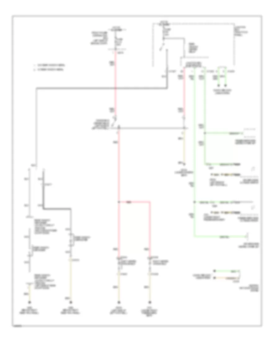
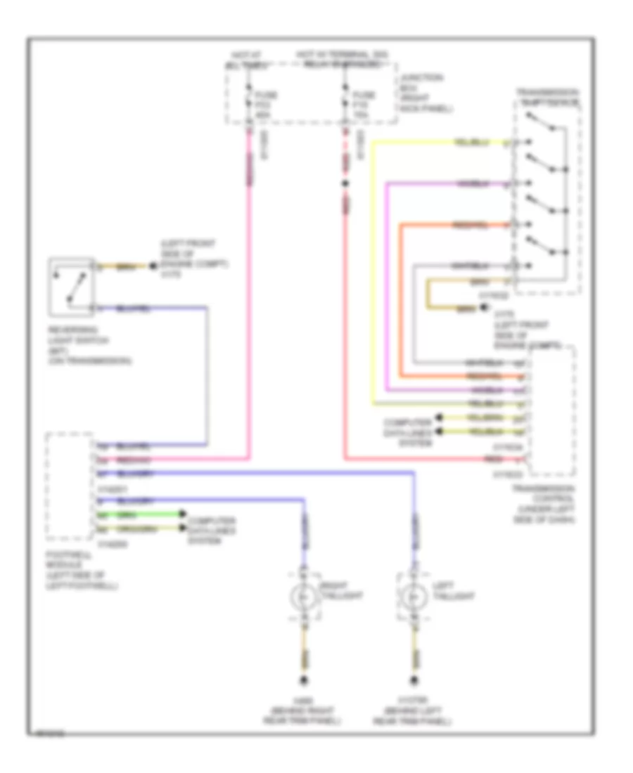
Backup Lamps Wiring Diagram for MINI Cooper Countryman JCW ALL4 2014
List of elements for Backup Lamps Wiring Diagram for MINI Cooper Countryman JCW ALL4 2014:
- (left front side of engine compt) x175
- Computer data lines system
- Footwell module (left side of left footwell)
- Fuse f15 15a
- Fuse f53 40a
- Hot at all times
- Hot w/ terminal 30g relay energized
- Junction box (right kick panel)
- Left taillight
- Red
- Reversing light switch (m/t) (on transmission)
- Right taillight
- Transmission control (under left side of dash)
- Transmission shift device
- X11003
- X11005
- X11632
- X11633
- X11634
- X13795 (behind left rear trim panel)
- X14260
- X14261
- X175 (left front side of engine compt)
- X490 (behind right rear trim panel)
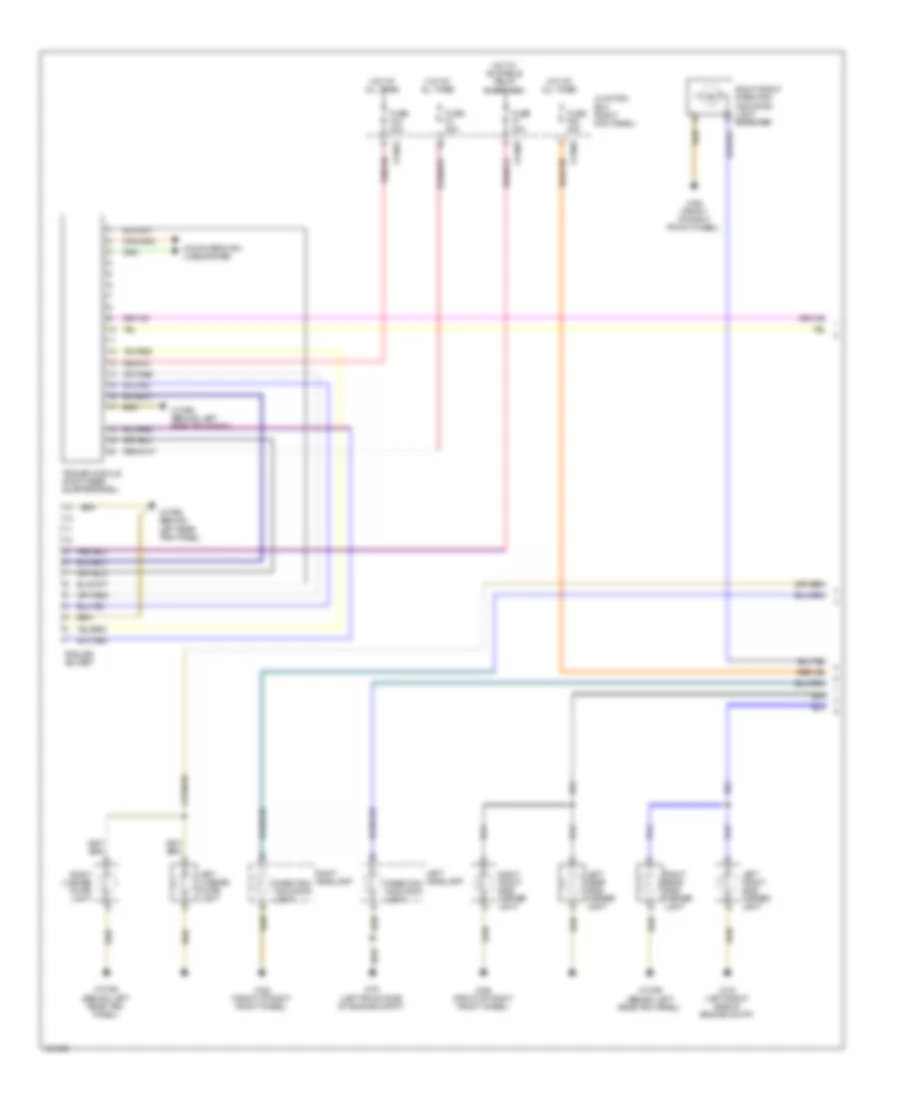
Exterior Lamps Wiring Diagram (1 of 2) for MINI Cooper Countryman JCW ALL4 2014
List of elements for Exterior Lamps Wiring Diagram (1 of 2) for MINI Cooper Countryman JCW ALL4 2014:
- Computer data lines system
- Direction indicator light
- Fuse f3 30a
- Fuse f43 20a
- Fuse f52 40a
- Fuse f7 20a
- Hot at all times
- Hot w/ bi-stable relay energized
- Junction box (right kick panel)
- Left front side marker light
- Left headlamp
- Left license plate light
- Left rear side marker light
- Right front direction indicator light repeater
- Right front side marker light
- Right headlamp
- Right license plate light
- Right rear side marker light
- Trailer module (right rear quarterpanel)
- Trailer socket
- X11001
- X11003
- X11005
- X13795 (behind left rear trim panel)
- X165 (front of right front wheel)
- X175 (left front side of engine compt)
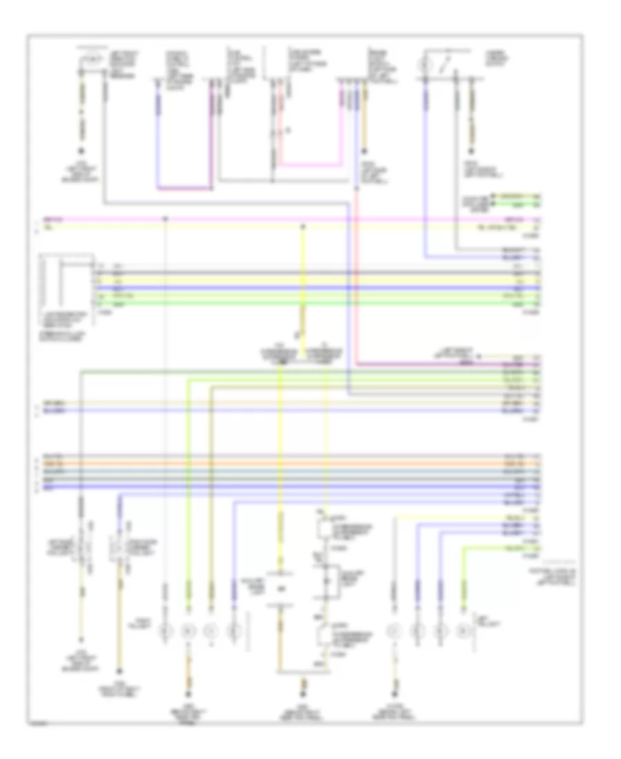
Exterior Lamps Wiring Diagram (2 of 2) for MINI Cooper Countryman JCW ALL4 2014
List of elements for Exterior Lamps Wiring Diagram (2 of 2) for MINI Cooper Countryman JCW ALL4 2014:
- (left side of left footwell) x2042
- Auxiliary brake light
- Brake light switch (left side of left footwell)
- Car access system (left top side of dash)
- Computer data lines system
- Dme control unit (left side of engine compt)
- Dynamic stability control (dsc) (left rear of engine compt)
- Footwell module (left side of left footwell)
- Hazard warning switch
- Interference suppressor filter 2
- Left front direction indicator light repeater
- Left side marker/ fog light
- Left taillight
- Lights/direction indicator/low beam stalk
- Right side marker/ fog light
- Right taillight
- Steering column switch cluster
- W/ interference suppressor filter
- W/o interference suppressor filter
- X10318
- X10900
- X10901
- X129
- X136
- X13795 (behind left rear trim panel)
- X14259
- X14260
- X14261
- X165 (front of right front wheel)
- X175 (left front side of engine compt)
- X1880
- X2042 (left side of left footwell)
- X490 (behind right rear trim panel)
- X60004
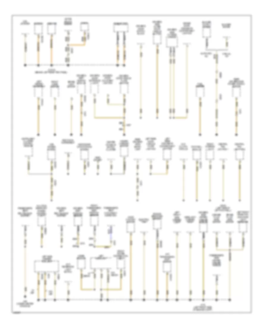
GROUND DISTRIBUTION
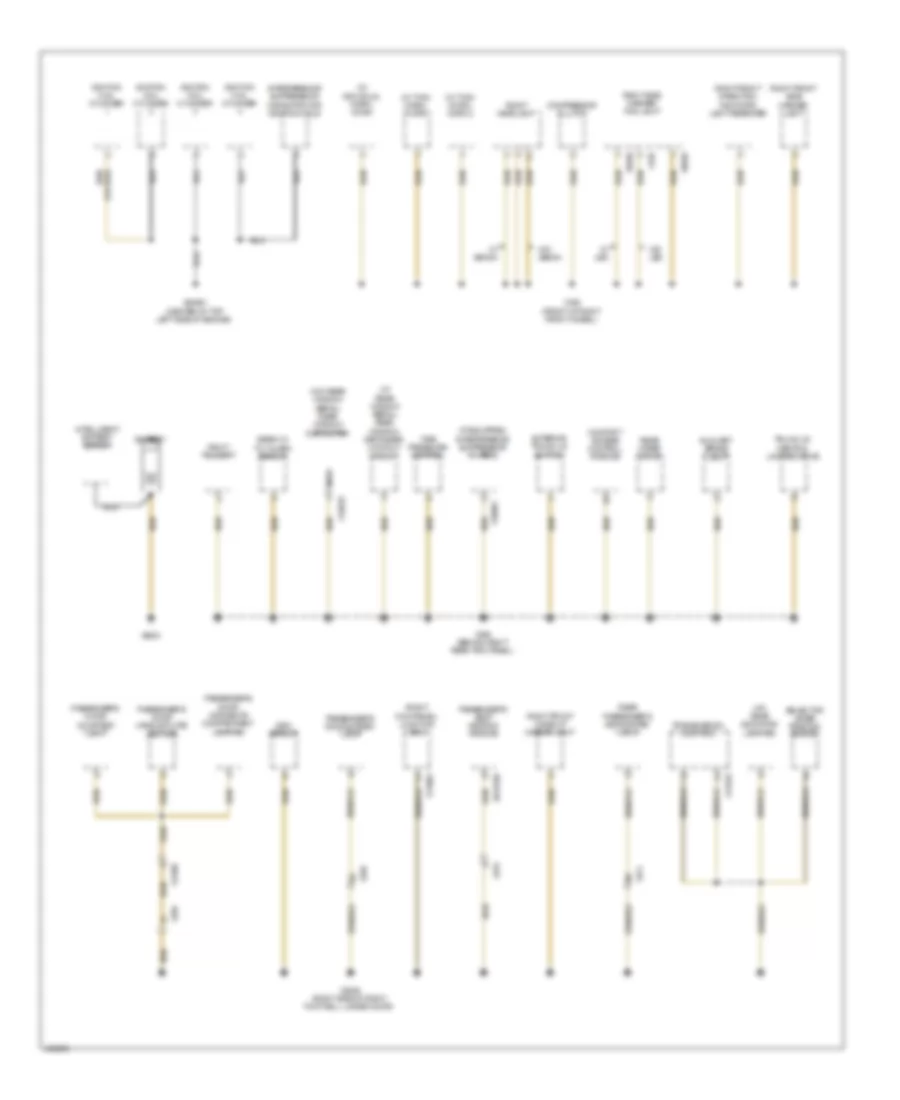
Ground Distribution Wiring Diagram (1 of 3) for MINI Cooper Countryman JCW ALL4 2014
List of elements for Ground Distribution Wiring Diagram (1 of 3) for MINI Cooper Countryman JCW ALL4 2014:
- (a/t) gear indicator lighting
- (if equipped) interference suppressor filter 2
- (right kick panel) junction box
- (w/ individual horn) horn
- (w/ rear window aerial) rear window defogger lockout circuit
- (w/ twin horn) horn
- (w/ twin horn) horn 2
- (w/o rear window aerial) rear window defroster
- Auxiliary brake light
- Battery
- Comfort access control module
- Compressor clutch
- Dsc sensor
- Exterior trunk lid button
- Ignition coil cylinder
- Intelligent battery sensor
- Interference suppression capacitor for ignition coils
- Nca
- Passenger's door courtesy light
- Passenger's door handle plate lighting
- Passenger's door oddments compartment lighting
- Passenger's door system lock
- Passenger's seat heating module
- Rear passenger's side system lock
- Rear wiper drive
- Right front direction indicator light repeater
- Right front make-up mirror light
- Right front side marker light
- Right headlight
- Right side marker/ fog light
- Right taillight
- Selector lever position switch
- Siren w/ tilt alarm sensor
- Tire pressure control
- Transmission control
- Trunk lid central locking drive
- W/ led
- W/ xenon
- W/o led
- W/o xenon
- X013709
- X10901
- X11002
- X11633
- X13018
- X13567
- X136
- X165 (front of right front wheel)
- X256
- X274
- X279
- X2846 (right side of right footwell, under door)
- X490 (behind right rear trim panel)
- X5550
- X6402
- X64561 (center of top left side of engine)
- X9039
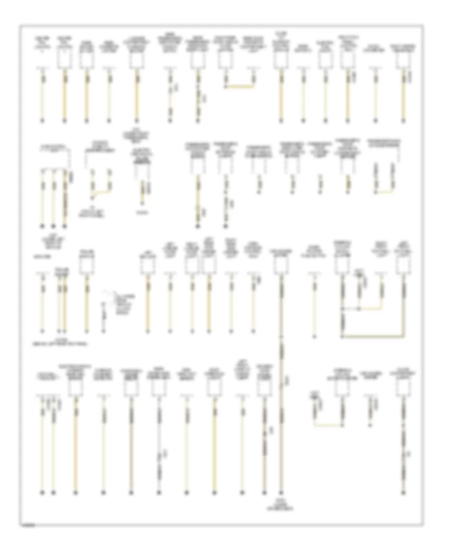
Ground Distribution Wiring Diagram (2 of 3) for MINI Cooper Countryman JCW ALL4 2014
List of elements for Ground Distribution Wiring Diagram (2 of 3) for MINI Cooper Countryman JCW ALL4 2014:
- (a/t) transmission shift device
- (m/t) clutch module
- (m/t) reversing light switch
- Active sound design
- Additional instrument
- Automatic a/c
- Base plate
- Blower motor
- Blower output stage
- Brake fluid level switch
- Brake light switch
- Car access system
- Center console switch cluster
- Central rail lighting 1
- Central rail lighting 2
- Combox
- Driver door oddments compartment lighting
- Driver's door courtesy lighting
- Driver's door entrance light
- Driver's door handle plate lighting
- Driver's door switch block
- Driver's seat belt buckle contact
- Driver's seat heating module
- Driver's seat position sensor
- Driver's side heated washer nozzle
- Driver's side outer door handle button
- Driver's side outside mirror
- Electric fan
- Engine breather heater 1
- Footwell module
- Front cigar lighter
- Front interior light
- Front passenger's seat position sensor
- Front power distribution box
- Fuel heater
- Hazard warning switch
- Headlight washer pump
- Heating/air conditioning system
- Hood contact switch
- Instrument cluster control module
- Left front direction indicator light repeater
- Left front side marker light
- Left headlight
- Left heated windshield
- Left rear door handle plate lighting
- Left rear oddments compartment lighting
- Left side marker/ fog light
- Manual a/c
- Mini joystick
- Multiple restraint system control unit
- Nca
- Obdii socket
- Passenger's seat belt buckle contact
- Passenger's seat occupancy detection
- Passenger's side heated washer nozzle
- Radio
- Rear driver's side entry lamp
- Rear drivers side power window switch
- Usb hub
- W/ led
- W/ xenon
- W/o led
- W/o xenon
- Washer fluid level switch
- Wiper module
- X10318
- X11632
- X129
- X13016 (behind left rear trim panel)
- X13443
- X13709
- X13812
- X14261
- X175 (left front side of engine compt)
- X18069
- X1879
- X2042 (left side of left footwell)
- X257
- X273
- X275
- X279
- X34130
- X4013
- X46 (under center console)
- X5548
- X6056
- X65399
- X9024
- X9331
Ground Distribution Wiring Diagram (3 of 3) for MINI Cooper Countryman JCW ALL4 2014
List of elements for Ground Distribution Wiring Diagram (3 of 3) for MINI Cooper Countryman JCW ALL4 2014:
- (not used)
- (right kick panel) junction box
- All-wheel drive vehicle clutch shield
- Amplifier
- Car access system
- Center rail lighting
- Dc/dc converter
- Dme control unit
- Driver's door system lock
- Dynamic stability control (dsc)
- Electric fuel pump
- Electro- mechanical power steering
- Electrochromic interior rear view mirror
- Footwell module
- Glove compartment light
- Inner tailgate push-button
- Interior movement detector
- Left front footwell light
- Left front make-up mirror light
- Left license plate light
- Left rear side marker light
- Left taillight
- Luggage compartment charging socket
- Nca
- Park distance control (pdc)
- Passenger's door courtesy light
- Passenger's door entrance light
- Passenger's door handle plate lighting
- Passenger's door oddments compartment lighting
- Passenger's door power window switch
- Passenger's side outer door handle button
- Passenger's side outside mirror
- Rain/ headlight sensor
- Rear cigarette lighter
- Rear door oddments compartment light
- Rear driver side system lock
- Rear passenger's side door entry light
- Rear passenger's side power window switch
- Rear socket 2
- Rear socket outlet
- Right front footwell light
- Right heated windshield
- Right license plate light
- Right rear door handle plate lighting
- Right rear side marker light
- Roof operating unit
- Slide/ tilt sunroof control module
- Steering column switch cluster
- Trailer module
- Trailer socket
- Windshield heater relay
- X10318
- X11007
- X13004
- X13446
- X13795 (behind left rear trim panel)
- X14260
- X14261
- X15
- X151 (under front passenger's seat)
- X167 (under left front of vehicle)
- X19527
- X2184 (under driver's seat)
- X256
- X257
- X273
- X274
- X300
- X4 (top of left front wheel)
- X60004
- X60233
- X9331
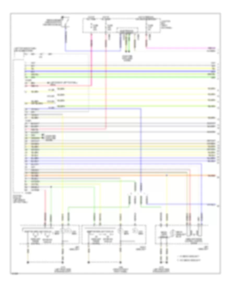
HEADLIGHTS
Headlights Wiring Diagram (1 of 2) for MINI Cooper Countryman JCW ALL4 2014
List of elements for Headlights Wiring Diagram (1 of 2) for MINI Cooper Countryman JCW ALL4 2014:
- (left side of left footwell) x2042
- (left top side of dash) car access system
- Adaptive headlight module
- Computer data lines system
- Electronics junction box
- Footwell module (left side of left footwell)
- Fuse f19 5a
- Fuse f52 40a
- Fuse f53 40a
- Headlamp range control
- Headlamp range control position motor
- High beam
- Hot at all times
- Hot w/ terminal 30g relay energized
- Junction box (right kick panel)
- Left headlight
- Low beam
- Parking brake warning switch (center console)
- Right headlight
- Swiveling module
- W/ led
- W/ xenon headlight
- W/o led
- W/o xenon headlight
- X11002
- X11005
- X11008
- X14259
- X14260
- X14261
- X14272
- X15
- X165 (front of right front wheel)
- X175 (left front side of engine compt)
- Xenon headlight bulb
- Xenon lamps module
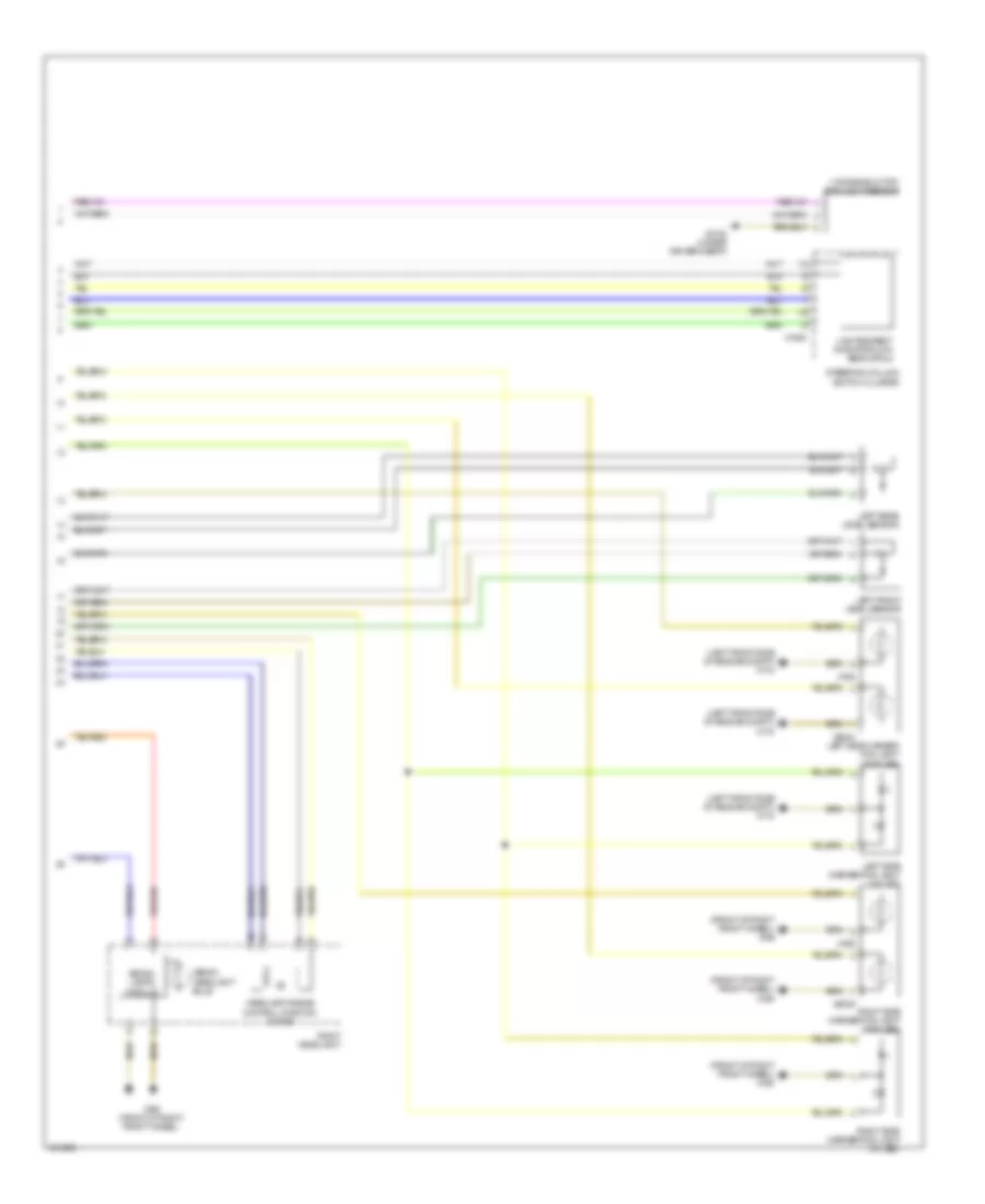
Headlights Wiring Diagram (2 of 2) for MINI Cooper Countryman JCW ALL4 2014
List of elements for Headlights Wiring Diagram (2 of 2) for MINI Cooper Countryman JCW ALL4 2014:
- (front of right front wheel) x165
- (left front side of engine compt) x175
- (windshield top) rain/light sensor
- Headlamp range control position motor
- Left front level sensor
- Left rear level sensor
- Left side marker/ fog light (w/o led)
- Left side marker/fog light (w/ led)
- Lights/direct indicator/low beam stalk
- Right headlight
- Right side marker/fog light (w/ led)
- Right side marker/fog light (w/o led)
- Steering column switch cluster
- X165 (front of right front wheel)
- X1880
- X2184 (under driver's seat)
- X768
- X769
- X9024
- X9039
- Xenon headlight bulb
- Xenon lamps module
HORN
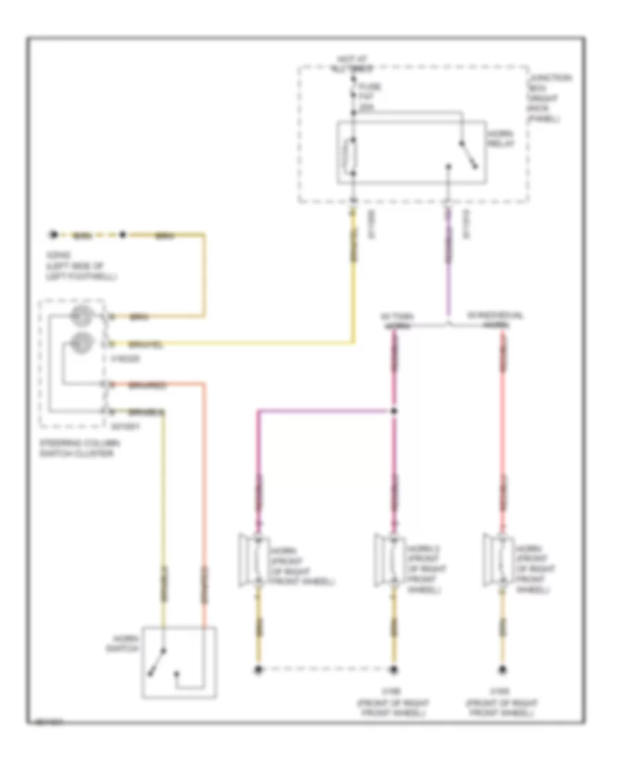
Horn Wiring Diagram for MINI Cooper Countryman JCW ALL4 2014
List of elements for Horn Wiring Diagram for MINI Cooper Countryman JCW ALL4 2014:
- (front of right front wheel)
- (left side of left footwell)
- Fuse f47 20a
- Horn (front of right front wheel)
- Horn 2 (front of right front wheel)
- Horn relay
- Horn switch
- Hot at all times
- Junction box (right kick panel)
- Steering column switch cluster
- W/ individual horn
- W/ twin horn
- X01001
- X11006
- X11010
- X165
- X18325
- X2042
INSTRUMENT CLUSTER
Instrument Cluster Wiring Diagram for MINI Cooper Countryman JCW ALL4 2014
List of elements for Instrument Cluster Wiring Diagram for MINI Cooper Countryman JCW ALL4 2014:
- Additional instrument
- Computer data lines system
- Electric fuel pump (top of fuel tank)
- Electronics junction box
- Fuse f29 5a
- Hot at all times
- Instrument cluster control module
- Junction box (right kick panel)
- Left front brake pad wear sensor (front of left front wheel)
- Nca
- Outside temperature sensor (behind right side of front bumper)
- Parking brake warning switch (center console)
- Right rear brake pad wear sensor (behind right rear wheel)
- Right tank half fuel level sensor
- X11002
- X11006
- X14272
- X15
- X2042 (left side of left footwell)
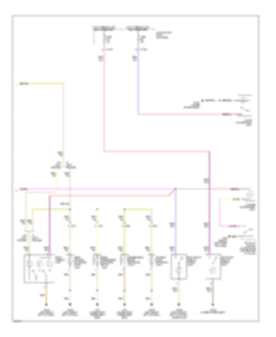
INTERIOR LIGHTS
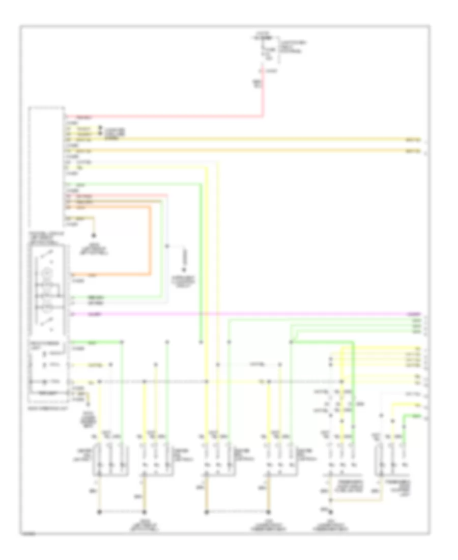
Courtesy Lamps Wiring Diagram (1 of 3) for MINI Cooper Countryman JCW ALL4 2014
List of elements for Courtesy Lamps Wiring Diagram (1 of 3) for MINI Cooper Countryman JCW ALL4 2014:
- Center rail lighting 1
- Center rail lighting 2
- Center rail lighting 3
- Center rail lighting 4
- Computer data lines system
- Footwell module (left side of left footwell)
- Front interior light
- Fuse f4 30a
- Hot at all times
- Instrument illumination circuit
- Junction box (right kick panel)
- Passenger's door courtesy light
- Passenger's door handle plate lighting
- Roof operating unit
- Top light
- X11007
- X14259
- X14260
- X14261
- X14286
- X14288
- X151 (under front passenger's seat)
- X2042 (left side of left footwell)
- X2184 (under driver's seat)
- X256
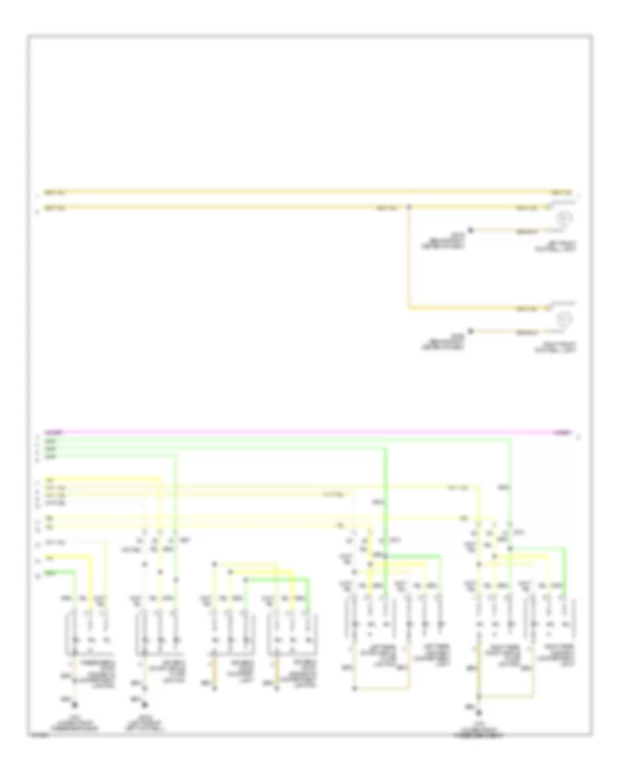
Courtesy Lamps Wiring Diagram (2 of 3) for MINI Cooper Countryman JCW ALL4 2014
List of elements for Courtesy Lamps Wiring Diagram (2 of 3) for MINI Cooper Countryman JCW ALL4 2014:
- Driver's door courtesy light
- Driver's door handle plate lighting
- Driver's door oddments compartment lighting
- Left front footwell light
- Left rear door handle plate lighting
- Left rear oddment compartment light
- Passenger's door oddments compartment lighting
- Right front footwell light
- Right rear door handle plate lighting
- Right rear oddment compartment light
- X151 (under front passenger's seat)
- X2042 (left side of left footwell)
- X257
- X273
- X3279 (behind right center of dash)
- X3456 (behind right center of dash)
Courtesy Lamps Wiring Diagram (3 of 3) for MINI Cooper Countryman JCW ALL4 2014
List of elements for Courtesy Lamps Wiring Diagram (3 of 3) for MINI Cooper Countryman JCW ALL4 2014:
- Driver's door entrance light
- Front interior light
- Fuse f16 10a
- Fuse f20 10a
- Glove compartment light
- Hot w/ terminal 30g relay energized
- Junction box (right kick panel)
- Left front make-up mirror light
- Luggage compartment light
- Passenger's door entrance light
- Rear driver's door side entry lamp
- Rear passenger's door side entry lamp
- Right front make-up mirror light
- Trunk lid central locking drive (center rear of trunk)
- W/ light package
- W/o light package
- X11006
- X11007
- X151 (under front passenger's seat)
- X2042 (left side of left footwell)
- X2184 (under driver's seat)
- X256
- X257
- X273
- X274
- X2846 (right side of right footwell, under door)
- X490 (behind right rear trim panel)
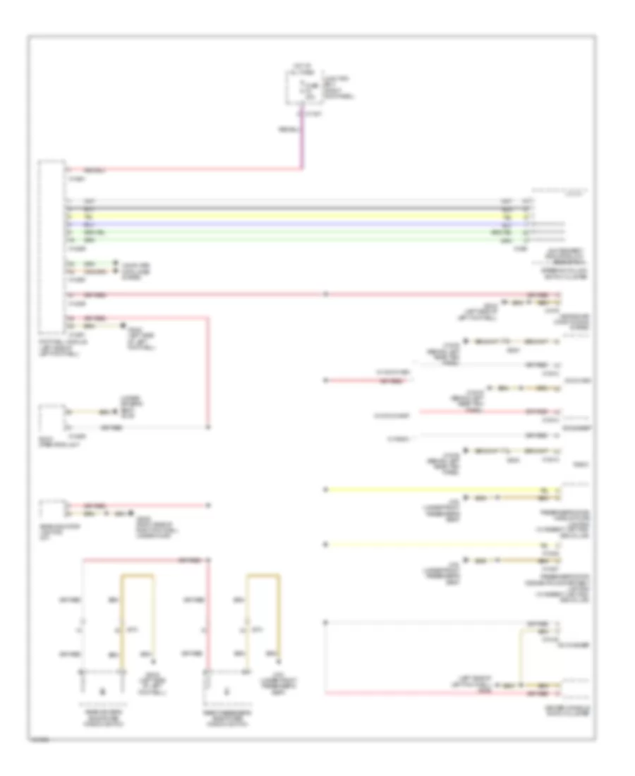
Instrument Illumination Wiring Diagram for MINI Cooper Countryman JCW ALL4 2014
List of elements for Instrument Illumination Wiring Diagram for MINI Cooper Countryman JCW ALL4 2014:
- (left side of left footwell) x2042
- (under driver's seat) x2184
- Ccc/champ
- Ccc/m-ask
- Cd changer
- Center console switch cluster
- Computer data lines system
- Footwell module (left side of left footwell)
- Fuse f4 30a
- Gear indicator lighting (a/t)
- Heating/air conditioning system
- Hot at all times
- Junction box (right kick panel)
- Lights/direct indicator/low beam stalk
- Passenger's door handle plate lighting (w/ ambient lighting, 3rd color)
- Passenger's door oddments compartment lighting (w/ ambient lighting, 3rd color)
- Radio
- Rear driver's side power window switch
- Rear passenger's side power window switch
- Roof operating unit
- Steering column switch cluster
- W/ ccc/champ
- W/ ccc/m-ask
- W/ radio
- X11007
- X13016 (behind left rear trim panel)
- X13425
- X13812
- X14259
- X14260
- X14261
- X14286
- X14487
- X151 (under front passenger's seat)
- X18180
- X1879
- X1880
- X2042 (left side of left footwell)
- X273
- X274
- X2846 (right side of right footwell, under door)
- X9331
NAVIGATION
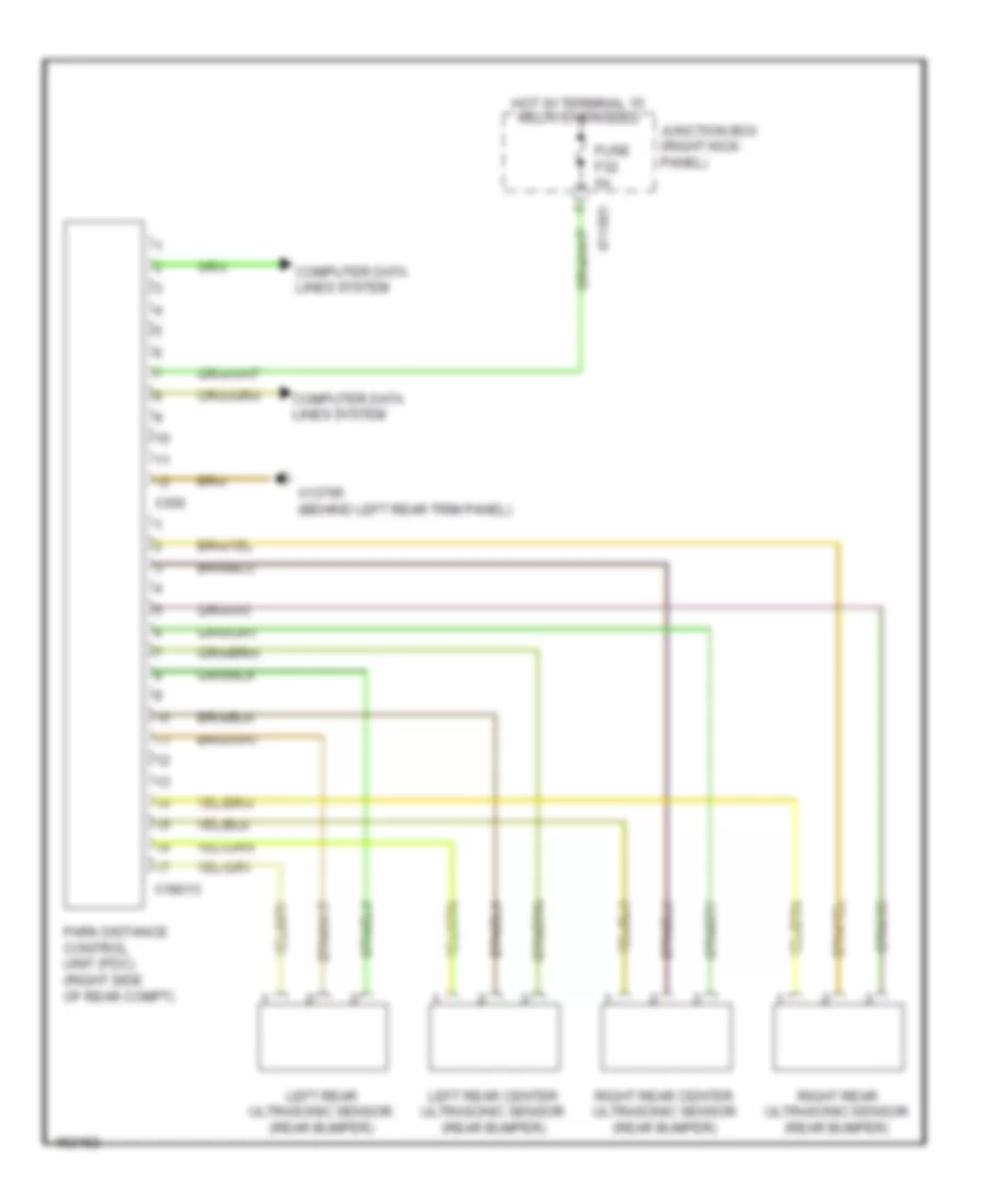
Navigation Wiring Diagram for MINI Cooper Countryman JCW ALL4 2014
List of elements for Navigation Wiring Diagram for MINI Cooper Countryman JCW ALL4 2014:
- Computer data lines system
- Fuse f32 5a
- Hot w/ terminal 15 relay energized
- Junction box (right kick panel)
- Left rear center ultrasonic sensor (rear bumper)
- Left rear ultrasonic sensor (rear bumper)
- Park distance control unit (pdc) (right side of rear compt)
- Right rear center ultrasonic sensor (rear bumper)
- Right rear ultrasonic sensor (rear bumper)
- X11001
- X13795 (behind left rear trim panel)
- X18013
- X300
POWER DISTRIBUTION
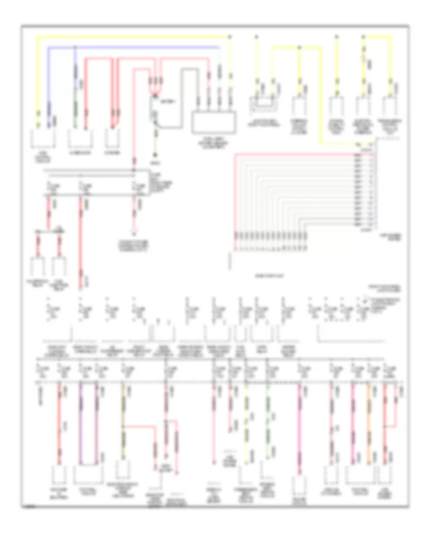
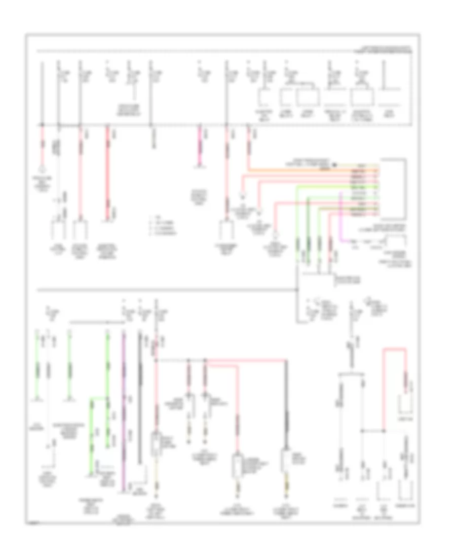
Power Distribution Wiring Diagram (1 of 3) for MINI Cooper Countryman JCW ALL4 2014
List of elements for Power Distribution Wiring Diagram (1 of 3) for MINI Cooper Countryman JCW ALL4 2014:
- (not used)
- (right kick panel) junction box
- 1.6l
- 1.6l turbo
- A/c compressor relay
- Additional instrument
- Alternator
- Amplifier (if equipped)
- Battery
- Car access system
- Dme control module
- Driver's seat heating module
- Dynamic stability control (dsc)
- Electro- mechanical power steering
- Electrochromic interior rear view mirror
- Footwell module
- Front washer pump relay
- Fuel injectors relay
- Fuel pump relay
- Fuse box (right rear of engine compt)
- Fuse f10 10a
- Fuse f10 30a
- Fuse f11 15a
- Fuse f2 30a
- Fuse f24 10a
- Fuse f25 15a
- Fuse f26 5a
- Fuse f27 7.5a
- Fuse f28 15a
- Fuse f29 5a
- Fuse f3 30a
- Fuse f36 5a
- Fuse f39 5a
- Fuse f4 30a
- Fuse f40 30a
- Fuse f41 30a
- Fuse f42 30a
- Fuse f43 20a
- Fuse f46 20a
- Fuse f47 20a
- Fuse f48 30a
- Fuse f49 30a
- Fuse f50 15a
- Fuse f51 40a
- Fuse f52 40a
- Fuse f53 40a
- Fuse f60 125a
- Fuse f67 150a
- Fuse f68 40a
- Fuse f8 30a
- Fuse f9 30a
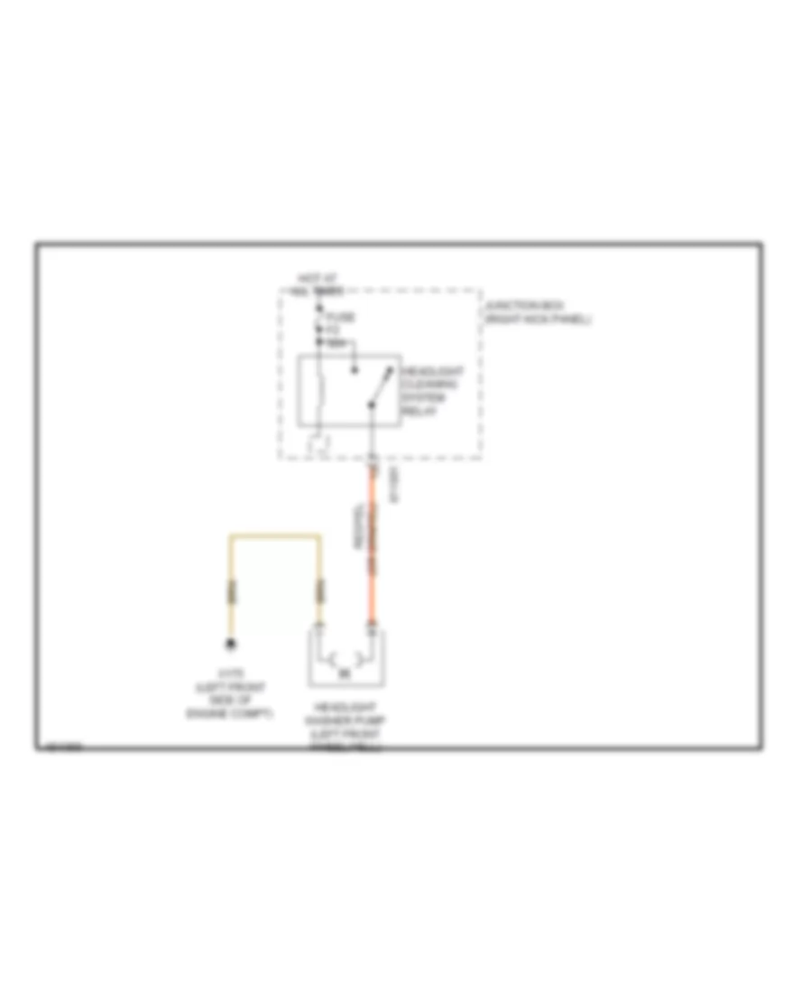
- Headlight cleaning system relay
- Heater blower relay
- Horn relay
- Intelligent battery sensor (on battery)
- Junction box (right kick panel)
- Nca
- Obdii socket
- Passenger's seat heating module
- Rear driver's side power window relay
- Rear washer pump relay
- Rear window defroster relay
- Rear window wiper relay
- Red
- Selector lever position switch
- Siren w/ tilt alarm sensor
- Start stop unit
- Starter
- Steering column switch cluster
- To electronics junction box (diagram 3 of 3)
- To front power distribution box (diagram 2 of 3)
- Trailer module
- Transmission control module (a/t)
- Usb hub (w/ combox)
- Valvetronic relay
- X013709
- X10318
- X11001
- X11002
- X11005
- X11006
- X11007
- X11008
- X11009
- X11633
- X13020
- X13709
- X14027
- X14260
- X14261
- X14272
- X15
- X1716
- X17177
- X18090
- X1880
- X2498
- X275
- X279
- X34117
- X60004
- X60234
- X6060
- X6401
- X6402
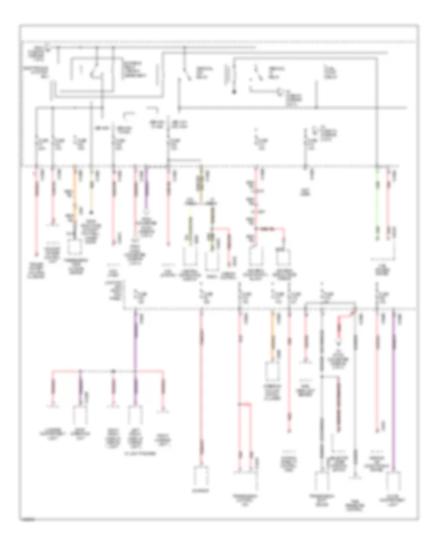
Power Distribution Wiring Diagram (2 of 3) for MINI Cooper Countryman JCW ALL4 2014
List of elements for Power Distribution Wiring Diagram (2 of 3) for MINI Cooper Countryman JCW ALL4 2014:
- (left side of engine compt) front power distribution box
- (not used)
- (right kick panel) junction box
- (right side of right footwell, under door) x2846
- 1.6l
- 1.6l turbo
- Auc sensor
- Baseplate
- Car access system
- Combox
- Crankcase ventilation heater relay
- Dc/dc converter (under left side of dash)
- Dme control unit
- Dme relay
- Driver's seat heating module
- Dsc sensor
- Dynamic stability control (dsc)
- Electric fan relay
- Electric fan relay 2 (1.6l turbo)
- Electro- mechanical power steering
- Electrochromic interior rearveiw mirror
- Electronics junction box
- From fuse box (diagram 1 of 3)
- From fuse f13 (diagram 3 of 3)
- From junction box (diagram 3 of 3)
- From terminal 15 relay (diagram 3 of 3)
- Front cigar lighter
- Fuse f01 7.5a
- Fuse f010 15a
- Fuse f06 25a
- Fuse f07 7.5a
- Fuse f08 40a
- Fuse f09 30a
- Fuse f12 5a
- Fuse f32 5a
- Fuse f33 5a
- Fuse f34 7.5a
- Fuse f35 5a
- Fuse f44 20a
- Fuse fl10 50a
- Fuse fl12 30a
- Fuse fl3 40a
- Fuse fl4 80a
- Fuse fl6 40a
- Fuse fl9 50a
- Luggage compartment charging socket
- Mirror adjustment switch
- Nca
- Park distance control (pdc)
- Passenger's seat heating module
- Rear cigarette lighter
- Rear socket 2
- Rear socket outlet
- Red
- Terminal 15 relief relay
- To junction box (diagram 3 of 3)
- Ulf sbx (if equipped)
- Ulf sbx h (if equipped)
- Usb hub
- W/ combox
- W/o combox
- Windscreen heater relay
- Wiper relay 1
- Wiper relay 2
- X013709
- X10318
- X11001
- X11002
- X11003
- X11007
- X11008
- X13566
- X13709
- X14133
- X15
- X151 (under front passenger's seat)
- X17177
- X17397
- X2042 (left side of left footwell)
- X257
- X275
- X279
- X300
- X34130
- X4010
- X4013
- X4015
- X4545
- X4844
- X60004
- X60233
- X625
Power Distribution Wiring Diagram (3 of 3) for MINI Cooper Countryman JCW ALL4 2014
List of elements for Power Distribution Wiring Diagram (3 of 3) for MINI Cooper Countryman JCW ALL4 2014:
- (not used)
- Bi stable relay (variant- dependent)
- Car access system
- Ccc/ m-ask
- Central information display
- Comfort access control unit
- Driver's door switch block
- Driver's side outside mirror
- Dynamic stability control (dsc)
- Electronics junction box
- From b fuse f28 (diagram 1 of 3)
- From converter dc/dc (diagram 2 of 3)
- From dc/dc converter (diagram 2 of 3)
- Front interior light
- Fuel pump relay
- Fuse f13 10a
- Fuse f14 10a
- Fuse f15 15a
- Fuse f16 10a
- Fuse f17 10a
- Fuse f18 5a
- Fuse f19 5a
- Fuse f20 10a
- Fuse f21 10a
- Fuse f22 7.5a
- Fuse f23 10a
- Fuse f45 20a
- Fuse f6 30a
- Fuse f7 20a
- Glove compartment light
- Heating/ air conditioning system
- Jbe high
- Jbe high w/ msa
- Jbe low (or) high
- Junction box (right kick panel)
- Left front make up mirror light
- Luggage compartment light
- Mini joystick
- Mission control
- Nca
- Passenger's side outside mirror
- Radio
- Rain/ headlight sensor
- Red
- Right front make up mirror light
- Roof operating unit
- Selector lever position switch
- Steering column switch cluster
- Sunroof
- Terminal 30g relay
- Terminal relay
- Tire pressure control
- To dc/dc converter (diagram 2 of 3)
- To fuse f12 (diagram 2 of 3)
- To fuse f33 (diagram 2 of 3)
- Trailer socket (coupe & clubman)
- Transmission control (a/t)
- Transmission shift device
- W/ light package
- W/ radio
- W/o radio
- X10318
- X11001
- X11002
- X11003
- X11006
- X11007
- X11008
- X11009
- X11632
- X11633
- X13812
- X14286
- X15
- X1879
- X1880
- X256
- X257
- X2846 (right side of right footwell, under door)
- X9270
- X9997
POWER DOOR LOCKS
Power Door Locks Wiring Diagram (1 of 2) for MINI Cooper Countryman JCW ALL4 2014
List of elements for Power Door Locks Wiring Diagram (1 of 2) for MINI Cooper Countryman JCW ALL4 2014:
- (right side of right footwell, under door) x2846
- Can bus high
- Can bus low
- Computer data lines system
- Contact sig
- Electronics junction box
- Footwell module (left side of left footwell)
- Fuel filler flap central locking drive (left side of rear compt)
- Fuse f11 15a
- Fuse f28 15a
- Fuse f4 30a
- Fuse f52 40a
- Fuse f53 40a
- Fuse f8 30a
- Gnd
- Hot at all times
- Interior lights system
- Junction box (right kick panel)
- Lock sig
- Rear driver's side system lock (countryman) (in driver rear door)
- Rear passenger's side system lock (countryman) (in passenger rear door)
- Switch sig
- Term 30
- Unlock sig
- X11002
- X11005
- X11007
- X11010
- X11011
- X14260
- X14261
- X2042 (left side of left footwell)
- X2184 (under driver's seat)
- X273
- X274
Power Door Locks Wiring Diagram (2 of 2) for MINI Cooper Countryman JCW ALL4 2014
List of elements for Power Door Locks Wiring Diagram (2 of 2) for MINI Cooper Countryman JCW ALL4 2014:
- (center rear of trunk) trunk lid central locking drive
- Driver's door system lock (rear of driver's door)
- Exterior trunk lid button
- Heating/cooling conditioning system
- Interior lights system
- Passenger's door system lock (rear of passenger's door)
- Strip switch
- X1879
- X2184 (under driver's seat)
- X256
- X257
- X2846 (right side of right footwell, under door)
- X490 (behind right rear trim panel)
POWER MIRRORS
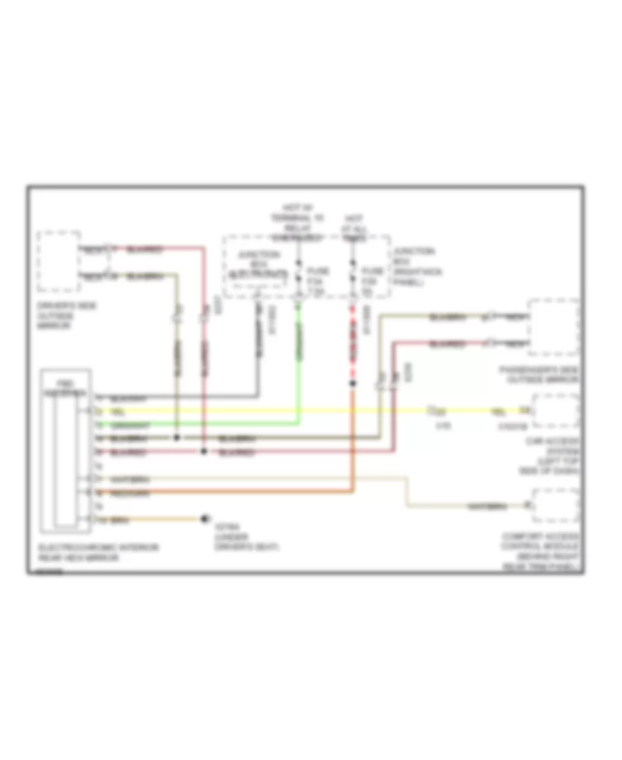
Electrochromic Mirror Wiring Diagram for MINI Cooper Countryman JCW ALL4 2014
List of elements for Electrochromic Mirror Wiring Diagram for MINI Cooper Countryman JCW ALL4 2014:
- Car access system (left top side of dash)
- Comfort access control module (behind right rear trim panel)
- Driver's side outside mirror
- Electrochromic interior rear view mirror
- Fbd receiver
- Fuse f26 5a
- Fuse f34 7.5a
- Hot at all times
- Hot w/ terminal 15 relay energized
- Junction box (right kick panel)
- Junction box electronics
- Nca
- Passenger's side outside mirror
- X10318
- X11002
- X11008
- X15
- X2184 (under driver's seat)
- X256
- X257
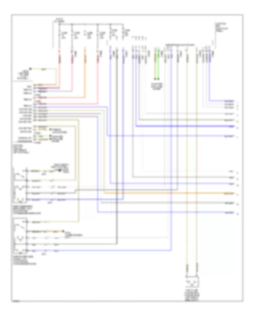
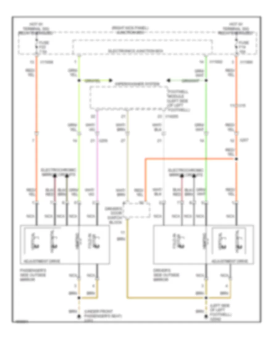
Power Mirrors Wiring Diagram for MINI Cooper Countryman JCW ALL4 2014
List of elements for Power Mirrors Wiring Diagram for MINI Cooper Countryman JCW ALL4 2014:
- (left side of left footwell) x2042
- (right kick panel) junction box
- (under front passenger's seat) x151
- Adjustment drive
- Driver's door switch block
- Driver's side outside mirror
- Electrochromic mirror circuits
- Electronics junction box
- Fold-in motor
- Footwell module (left side of left footwell)
- Fuse f14 10a
- Fuse f22 7.5a
- Heating
- Horizontal
- Hot w/ terminal 30g relay energized
- Motor fold-in
- Nca
- Passenger's side outside mirror
- Vertical
- Wiper/washer system
- X11002
- X11006
- X11008
- X14260
- X15
- X256
- X257
POWER SEATS
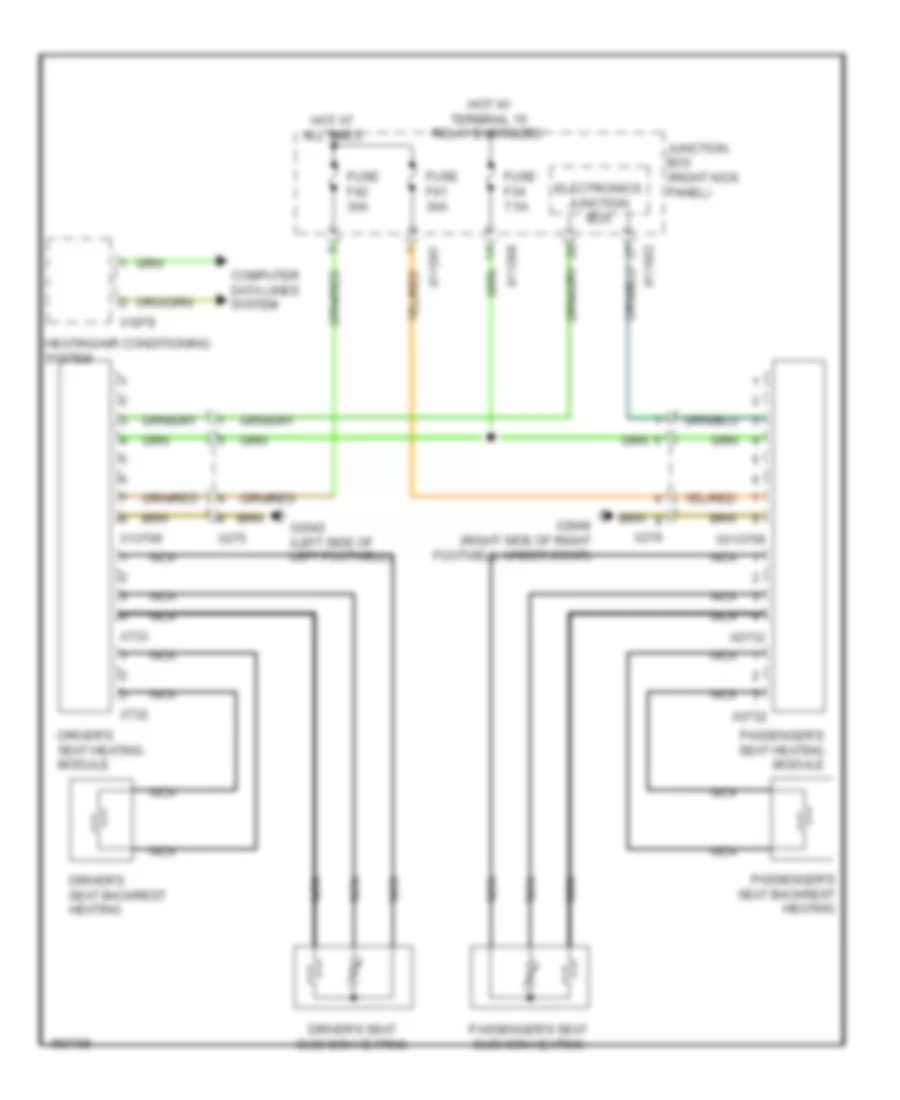
Power Seats Wiring Diagram for MINI Cooper Countryman JCW ALL4 2014
List of elements for Power Seats Wiring Diagram for MINI Cooper Countryman JCW ALL4 2014:
- Computer data lines system
- Driver's seat backrest heating
- Driver's seat cushion heating
- Driver's seat heating module
- Electronics junction box
- Fuse f34 7.5a
- Fuse f41 30a
- Fuse f42 30a
- Heating/air conditioning system
- Hot at all times
- Hot w/ terminal 15 relay energized
- Junction box (right kick panel)
- Nca
- Passenger's seat backrest heating
- Passenger's seat cushion heating
- Passenger's seat heating module
- X013709
- X0732
- X0733
- X11001
- X11002
- X11008
- X13709
- X1879
- X2042 (left side of left footwell)
- X275
- X279
- X2846 (right side of right footwell, under door)
- X732
- X733
POWER TOP/SUNROOF
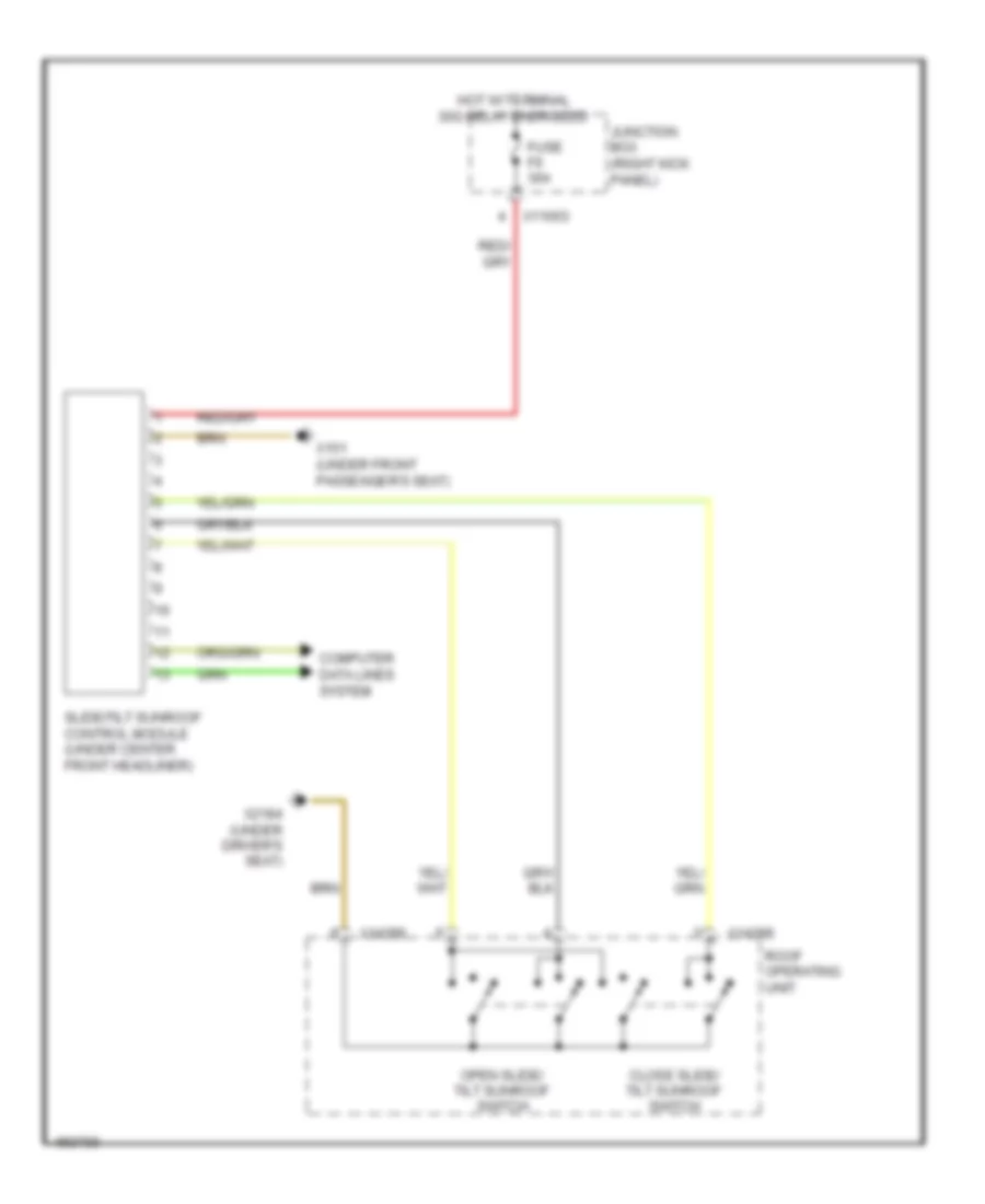
Power Top/Sunroof Wiring Diagram for MINI Cooper Countryman JCW ALL4 2014
List of elements for Power Top/Sunroof Wiring Diagram for MINI Cooper Countryman JCW ALL4 2014:
- Close slide/ tilt sunroof switch
- Computer data lines system
- Fuse f6 30a
- Hot w/ terminal 30g relay energized
- Junction box (right kick panel)
- Open slide/ tilt sunroof switch
- Roof operating unit
- Slide/tilt sunroof control module (under center front headliner)
- X11003
- X14286
- X14288
- X151 (under front passenger's seat)
- X2184 (under driver's seat)
POWER WINDOWS
Power Windows Wiring Diagram (1 of 2) for MINI Cooper Countryman JCW ALL4 2014
List of elements for Power Windows Wiring Diagram (1 of 2) for MINI Cooper Countryman JCW ALL4 2014:
- Center console control panel
- Computer data lines system
- Driver's door switch block
- Driver's window motor (front of driver's door)
- Electronics junction box
- Footwell module (left side of left footwell)
- Fuse f14 10a
- Fuse f4 30a
- Fuse f8 30a
- Heating/air conditioning system
- Hot at all times
- Hot w/ terminal 30g relay energized
- Junction box (right kick panel)
- Passenger's window motor (front of passenger's door)
- Rear driver's side power window motor (in driver's rear door)
- Rear passenger's side power window motor (in passenger's rear door)
- Strip switch
- X11002
- X11006
- X11007
- X11008
- X11011
- X14260
- X14261
- X1879
- X2042 (left side of left footwell)
- X256
- X257
- X273
- X274
- X2846 (right side of right footwell, under door)
Power Windows Wiring Diagram (2 of 2) for MINI Cooper Countryman JCW ALL4 2014
List of elements for Power Windows Wiring Diagram (2 of 2) for MINI Cooper Countryman JCW ALL4 2014:
- Interior lights system
- Passenger's door power window switch
- Rear driver's side power window switch
- Rear passenger's side power window switch
- X151 (under front passenger's seat)
- X2042 (left side of left footwell)
- X256
- X273
- X274
RADIO
Radio Wiring Diagram, with Amplifier (1 of 2) for MINI Cooper Countryman JCW ALL4 2014
List of elements for Radio Wiring Diagram, with Amplifier (1 of 2) for MINI Cooper Countryman JCW ALL4 2014:
- (18-21 not used)
- (31-33 not used)
- (37-38 not used)
- (behind left rear trim panel) x13016
- (under left side of dash) dc/dc converter
- Antenna diversity (right side of rear compt door)
- Aux-in connection
- Computer data lines system
- Diversity antenna circuit
- Front power distribution box (left side of engine compt)
- Fuse f23 10a
- Fuse f49 30a
- Fuse fl12 30a
- Hot at all times
- Hot w/ terminal 30g relay energized
- Interior lights system
- Jbe high w/ msa
- Jbe low or high
- Junction box (right kick panel)
- Mini joystick
- Most data bus circuit
- Nca
- Radio
- Red
- Roof antenna (center rear of roof)
- Voice control microphone (in overhead console)
- W/ antenna diversity
- W/o antenna diversity
- X013816
- X11003
- X11009
- X11411
- X13016 (behind left rear trim panel)
- X13174
- X13344
- X13386
- X1365
- X13812
- X13815
- X13816
- X14064
- X14066
- X15
- X16766
- X16792
- X1716
- X17414
- X4010
- X9331
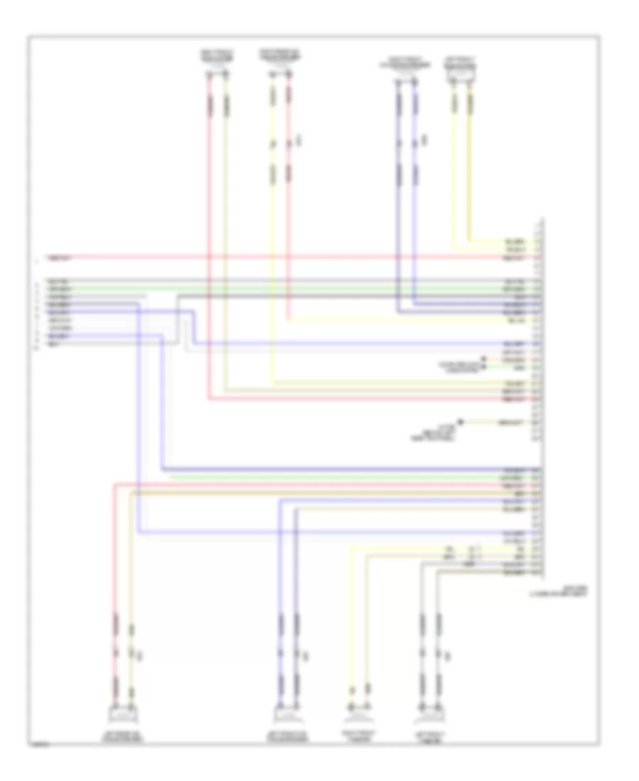
Radio Wiring Diagram, with Amplifier (2 of 2) for MINI Cooper Countryman JCW ALL4 2014
List of elements for Radio Wiring Diagram, with Amplifier (2 of 2) for MINI Cooper Countryman JCW ALL4 2014:
- Amplifier (under driver's seat)
- Computer data lines system
- Left front mid- range speaker
- Left front subwoofer
- Left front tweeter
- Left rear mid- range speaker
- Right front mid range speaker
- Right front sub woofer
- Right front tweeter
- Right rear mid- range speaker
- X13795 (behind left rear trim panel)
- X256
- X257
- X273
- X274
Radio Wiring Diagram, without Amplifier for MINI Cooper Countryman JCW ALL4 2014
List of elements for Radio Wiring Diagram, without Amplifier for MINI Cooper Countryman JCW ALL4 2014:
- (behind left rear trim panel) x13016
- (under left side of dash) dc/dc converter
- Antenna diversity (right side of rear compt door)
- Aux-in connection
- Computer data lines system
- Diversity antenna circuit
- Front power distribution box (left side of engine compt)
- Fuse f23 10a
- Fuse fl12 30a
- Hot at all times
- Hot w/ terminal 30g relay energized
- Interior lights system
- Jbe high w/ msa
- Jbe low or high
- Junction box (right kick panel)
- Left front mid-range speaker
- Left front subwoofer
- Left rear mid-range speaker
- Mini joystick
- Most data bus circuit
- Nca
- Radio
- Right front mid-range speaker
- Right front sub woofer
- Right rear mid-range speaker
- Roof antenna (center rear of roof)
- Voice control microphone (in overhead console)
- W/ antenna diversity
- W/o antenna diversity
- X013816
- X11003
- X11009
- X11411
- X13016 (behind left rear trim panel)
- X13175
- X13344
- X13365
- X13386
- X13812
- X13815
- X13816
- X13824
- X14064
- X14066
- X15
- X16766
- X16792
- X17414
- X256
- X257
- X273
- X274
- X4010
- X9331
SHIFT INTERLOCK
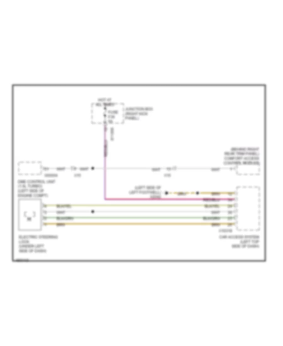
Shift Interlock Wiring Diagram for MINI Cooper Countryman JCW ALL4 2014
List of elements for Shift Interlock Wiring Diagram for MINI Cooper Countryman JCW ALL4 2014:
- (behind right rear trim panel) comfort access control module
- (left side of left footwell) x2042
- Car access system (left top side of dash)
- Dme control unit (1.6l turbo) (left side of engine compt)
- Electric steering lock (under left side of dash)
- Fuse f36 5a
- Hot at all times
- Junction box (right kick panel)
- X10318
- X11006
- X15
- X60004
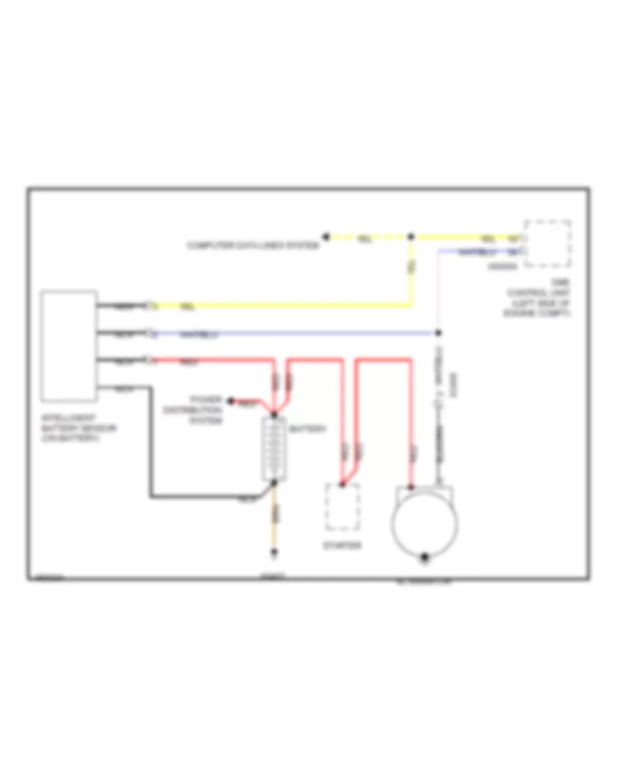
STARTING/CHARGING
Charging Wiring Diagram for MINI Cooper Countryman JCW ALL4 2014
List of elements for Charging Wiring Diagram for MINI Cooper Countryman JCW ALL4 2014:
- Alternator
- Battery
- Computer data lines system
- Dme control unit (left side of engine compt)
- Intelligent battery sensor (on battery)
- Nca
- Power distribution system
- Red
- Starter
- X2498
- X60004
- X6402
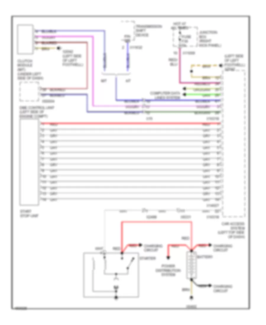
Starting Wiring Diagram for MINI Cooper Countryman JCW ALL4 2014
List of elements for Starting Wiring Diagram for MINI Cooper Countryman JCW ALL4 2014:
- (left side of left footwell) x2042
- A/t
- Battery
- Car access system (left top side of dash)
- Charging circuit
- Clutch module (m/t) (under left side of dash)
- Computer data lines system
- Dme control unit (left side of engine compt)
- Fuse f36 5a
- Hot at all times
- Junction box (right kick panel)
- M/t
- Nca
- P/n sig
- Power distribution system
- Red
- Start stop unit
- Starter
- Transmission shift device
- X10318
- X11006
- X11632
- X14027
- X15
- X2042 (left side of left footwell)
- X2498
- X60004
- X6402
- X9331
SUPPLEMENTAL RESTRAINTS
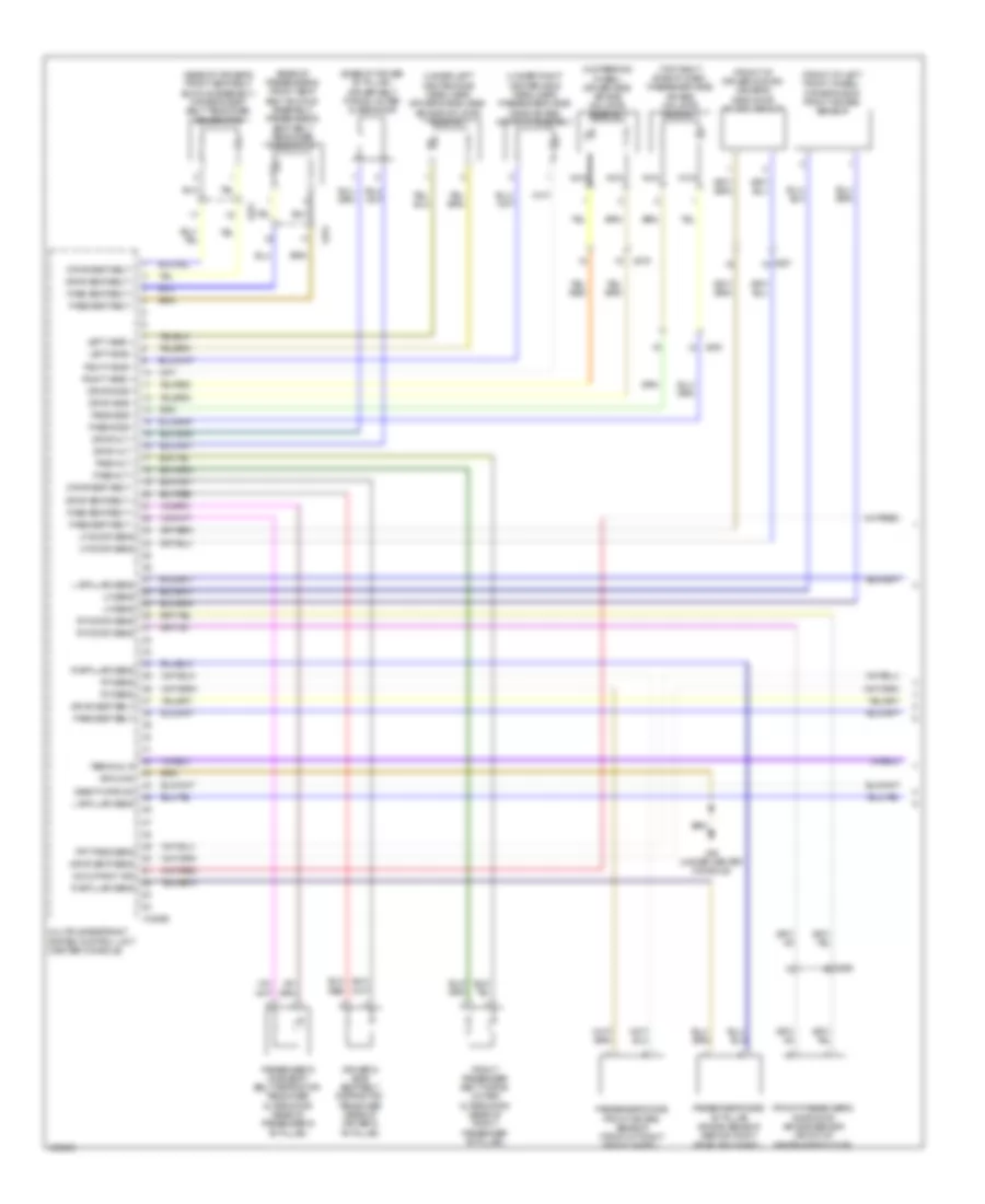
Supplemental Restraints Wiring Diagram (1 of 2) for MINI Cooper Countryman JCW ALL4 2014
List of elements for Supplemental Restraints Wiring Diagram (1 of 2) for MINI Cooper Countryman JCW ALL4 2014:
- (base of driver "b" pillar ) driver belt force limiter alternator
- (base of driver's front seat belt buckle assembly) driver's seat belt tensioner generator
- (base of passenger's front seat belt buckle assembly) passenger's seat belt tensioner generator
- (front of driver's door) driver's side door air bag sensor
- (front of left front wheel) driver's side front air bag sensor
- (in steering wheel) driver side air bag inflator assembly
- (top right side of dash) passenger side air bag inflator assembly
- (under left center side headliner) driver's side head air bag inflator assembly
- (under right center side headliner) passenger's side head air bag inflator assembly
- Deactivate ind
- Driver's side seat belt retractor tensioner (base of driver's "b" pillar)
- Drvr alt +
- Drvr alt -
- Drvr seat belt
- Drvr seat belt +
- Drvr seat belt -
- Drvr seat sens
- Drvr side +
- Drvr side -
- Front passenger belt force limiter alternator (base of front passenger "b" pillar)
- Front passenger's side door air bag sensor (front of passenger's door)
- Frt pass sens
- Ground
- L b-pillar sens
- Left head +
- Left head -
- Lf door sens
- Lf sens
- Multiple restraint system control unit (center console)
- Nca
- Occupancy sig
- Pass alt +
- Pass alt -
- Pass seat belt
- Pass seat belt +
- Pass seat belt -
- Pass side +
- Pass side -
- Passenger's side "b" pillar air bag sensor (behind right rear trim panel)
- Passenger's side front air bag sensor (front of right front wheel)
- Passenger's side seat belt retractor tensioner alternator (base of passenger's "b" pillar)
- R b-pillar sens
- Rf door sens
- Rf sens
- Right head +
- Right head -
- Terminal r
- X18069
- X256
- X257
- X275
- X279
- X46 (under center console)
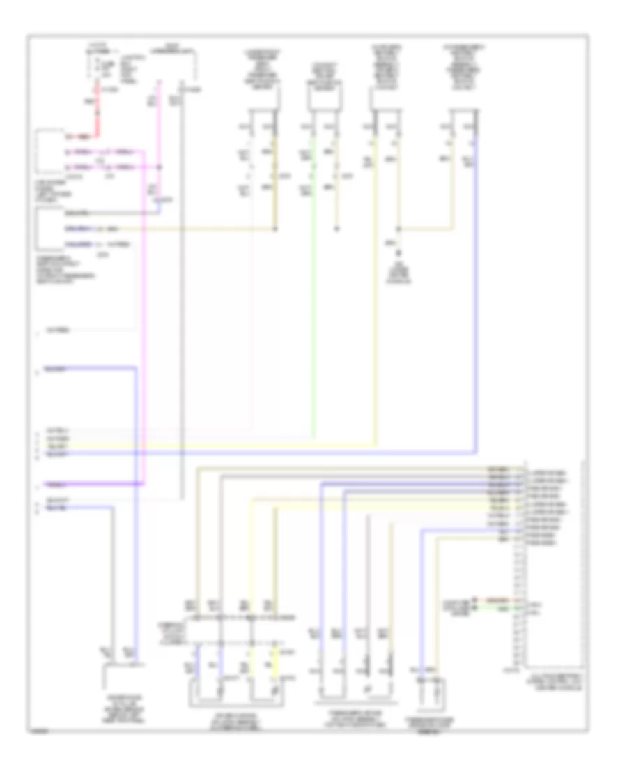
Supplemental Restraints Wiring Diagram (2 of 2) for MINI Cooper Countryman JCW ALL4 2014
List of elements for Supplemental Restraints Wiring Diagram (2 of 2) for MINI Cooper Countryman JCW ALL4 2014:
- (in driver's seat belt buckle assembly) driver's seat belt buckle contact
- (in passenger's seat belt buckle assembly) passenger's seat belt buckle contact
- (on right seat rail) driver seat position sensor
- (under front passenger seat) front passenger seat position sensor
- Can h
- Can l
- Car access system (left top side of dash)
- Clster air bag +
- Clster air bag -
- Computer data lines system
- Driver's air bag inflator assembly (in steering wheel)
- Driver's side "b" pillar air bag sensor (behind left rear trim panel)
- Fuse f51 40a
- Hot at all times
- Junction box (right kick panel)
- Multiple restraint system control unit (center console)
- Nca
- Pass air bag +
- Pass air bag -
- Pass knee +
- Pass knee -
- Passenger's air bag inflator assembly (top right side of dash)
- Passenger's knee air bag inflator assembly
- Passenger's seat occupancy detector (in front passenger's seat cushion)
- Red
- Roof operating unit
- Steering column switch cluster
- X01001
- X01071
- X01072
- X10179
- X10318
- X11006
- X14286
- X15
- X18325
- X275
- X279
- X46 (under center console)
TRANSMISSION
Transmission Wiring Diagram (1 of 2) for MINI Cooper Countryman JCW ALL4 2014
List of elements for Transmission Wiring Diagram (1 of 2) for MINI Cooper Countryman JCW ALL4 2014:
- Car access system (left top side of dash)
- Computer data lines system
- Fuse f15 15a
- Fuse f19 5a
- Fuse f26 5a
- Hot at all times
- Hot w/ terminal 30g relay energized
- Junction box (right kick panel)
- Red
- Transmission control module (under left side of dash)
- Transmission shift device
- X10318
- X11003
- X11008
- X11630
- X11631
- X11632
- X11633
- X11634
- X15
- X175 (left front side of engine compt)
- X2846 (right side of right footwell, under door)
Transmission Wiring Diagram (2 of 2) for MINI Cooper Countryman JCW ALL4 2014
List of elements for Transmission Wiring Diagram (2 of 2) for MINI Cooper Countryman JCW ALL4 2014:
- (right side of right footwell, under door) x2846
- All-wheel drive vehicle clutch (on rear of transaxle)
- Computer data lines system
- Dynamic stability control (dsc) (left rear of engine compt)
- Gear indicator lighting
- Interior lights system
- Left rocker switch
- Nca
- Red
- Right rocker switch
- Selector lever position switch (at base of gear selector)
- Steering column switch cluster
- X01006
- X01185
- X0465
- X13795 (behind left rear trim panel)
- X15
- X1880
TRUNK, TAILGATE, FUEL DOOR
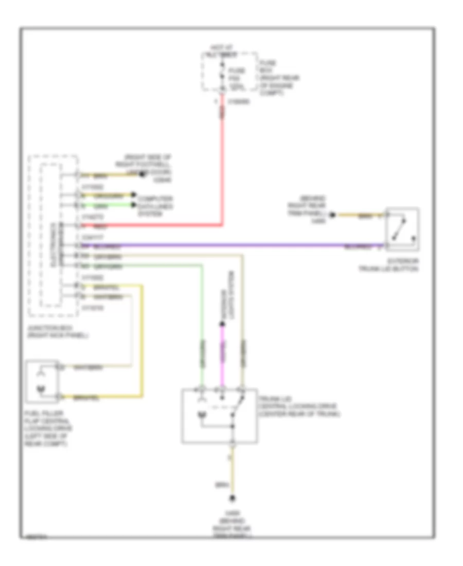
Trunk & Fuel Door Release Wiring Diagram for MINI Cooper Countryman JCW ALL4 2014
List of elements for Trunk & Fuel Door Release Wiring Diagram for MINI Cooper Countryman JCW ALL4 2014:
- (behind right rear trim panel) x490
- (right side of right footwell, under door) x2846
- Computer data lines system
- Exterior trunk lid button
- Fuel filler flap central locking drive (left side of rear compt)
- Fuse box (right rear of engine compt)
- Fuse f60 125a
- Hot at all times
- Junction box (right kick panel)
- Junction box electronics
- Lights system interior
- Red
- Trunk lid central locking drive (center rear of trunk)
- X11002
- X11010
- X14272
- X18090
- X34117
- X490 (behind right rear trim panel)
WARNING SYSTEMS
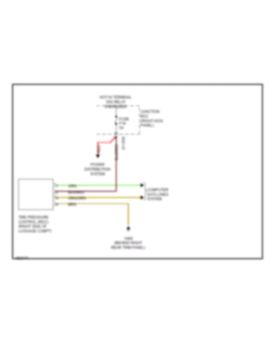
Warning Systems Wiring Diagram for MINI Cooper Countryman JCW ALL4 2014
List of elements for Warning Systems Wiring Diagram for MINI Cooper Countryman JCW ALL4 2014:
- Computer data lines system
- Fuse f19 5a
- Hot w/ terminal 30g relay energized
- Junction box (right kick panel)
- Power distribution system
- Red
- Tire pressure control (rdc) (right side of luggage compt)
- X11008
- X490 (behind right rear trim panel)
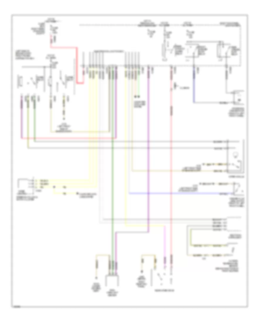
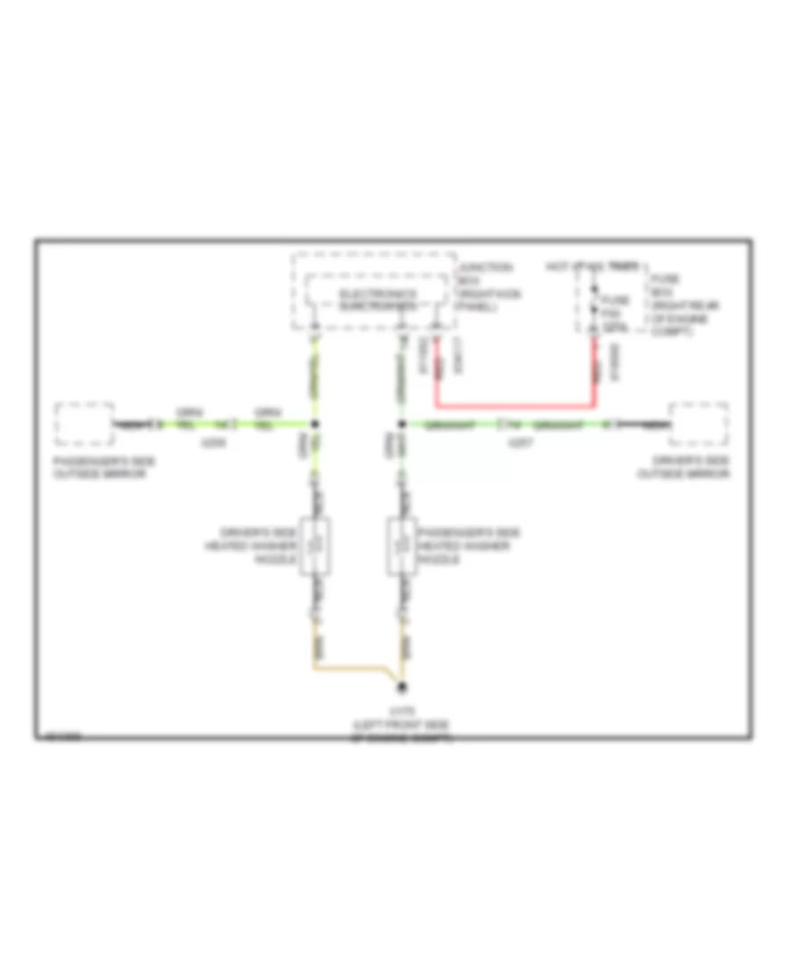
WIPER/WASHER
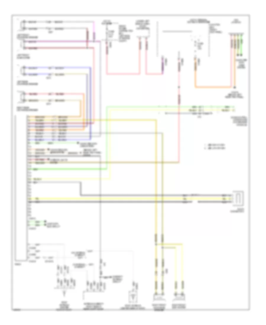
Front & Rear Wiper/Washer Wiring Diagram for MINI Cooper Countryman JCW ALL4 2014
List of elements for Front & Rear Wiper/Washer Wiring Diagram for MINI Cooper Countryman JCW ALL4 2014:
- (behind right side of front bumper)
- (left side of engine compt) front power distribution box
- (right kick panel) junction box
- Additional instrument
- Clubman
- Computer data lines system
- Electronics junction box
- Front washer pump relay
- Fuse box (right rear of engine compt)
- Fuse f09 30a
- Fuse f19 5a
- Fuse f25 15a
- Fuse f50 15a
- Fuse f60 125a
- Hot at all times
- Hot w/ terminal 30g relay energized
- Outside temperature sensor
- Rain/ headlight sensor
- Rear washer pump relay
- Rear window wiper relay
- Rear wiper drive
- Red
- Right rear trim panel)
- Steering column & switch cluster
- Washer fluid level switch (front of left front wheel)
- Windshield washer pump (front of left front wheel)
- Wiper module
- Wiper relay
- Wiper switch
- X10669
- X11002
- X11007
- X11008
- X11010
- X14272
- X15
- X175 (left front side of engine compt)
- X18090
- X1880
- X2184 (under driver's seat)
- X34117
- X4009
- X4010
- X4013
- X490 (behind
Headlamp Washer Wiring Diagram for MINI Cooper Countryman JCW ALL4 2014
List of elements for Headlamp Washer Wiring Diagram for MINI Cooper Countryman JCW ALL4 2014:
- Fuse f2 30a
- Headlight cleaning system relay
- Headlight washer pump (left front wheelwell)
- Hot at all times
- Junction box (right kick panel)
- X11001
- X175 (left front side of engine compt)
Washer Jet Heater Wiring Diagram for MINI Cooper Countryman JCW ALL4 2014
List of elements for Washer Jet Heater Wiring Diagram for MINI Cooper Countryman JCW ALL4 2014:
- Driver's side heated washer nozzle
- Driver's side outside mirror
- Electronics junction box
- Fuse box (right rear of engine compt)
- Fuse f60 125a
- Hot at all times
- Junction box (right kick panel)
- Nca
- Passenger's side heated washer nozzle
- Passenger's side outside mirror
- Red
- X11002
- X175 (left front side of engine compt)
- X18090
- X256
- X257
- X34117

 Čeština
 Dansk
Dansk Deutsch
 Ελληνικά
 English
 English
 Español
 Suomi
Suomi Français
 עברית
עברית Hrvatski
 Magyar
 Italiano
 日本語
日本語 한국어
한국어 Nederlands
 Polski
 Português
 Português
 Română
 Русский
 Slovenčina
 Slovenščina
 Svenska
 Türkçe
 中文 (中国)