Diagram sections — 14 (23 total)
AIR CONDITIONING COOLING FAN DEFOGGERS HORN POWER ANTENNA POWER DOOR LOCKS POWER MIRRORS POWER SEATS POWER WINDOWS RADIO STARTING/CHARGING TRANSMISSION TRUNK, TAILGATE, FUEL DOOR WIPER/WASHER
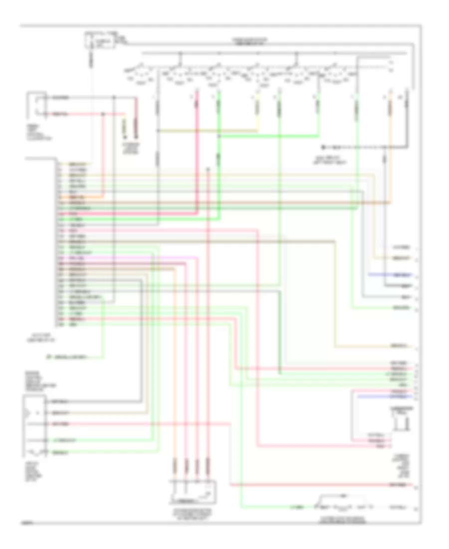
AIR CONDITIONING Air Conditioning Wiring Diagrams, Auto A/C (1 of 2) for Nissan Maxima SE 1993 List of elements for Air Conditioning Wiring Diagrams, Auto A/C (1 of 2) for Nissan Maxima SE 1993: 23 (below g300 (center of i/p) Air mix door motor (center of i/p) Auto amp B/l Def Engine control module (behind center console) F/d Foot Fresh vent control illumination Fuse 23 10a Fuse block Hot at all times Intake door motor (attached to front of heater unit) Interior lights system Left front seat) Mode door motor (center of i/p) Pnk Pos sw Thermistor Thermo control amp (right side of i/p) Vent Water cock solenoid (center rear of engine) Air Conditioning Wiring Diagrams, Auto A/C (2 of 2) for Nissan Maxima SE 1993 List of elements for Air Conditioning Wiring Diagrams, Auto A/C (2 of 2) for Nissan Maxima SE 1993: 43 (dohc) (dohc) (sohc) (front of vehichle) (left front of engine compt) (left front of engine compt, on liquid tank) (left g100 (right of engine compt) (sohc) 1994 vftc c A/c compressor clutch A/c relay (left front of engine compt) Ambient sensor Blower motor Cooling fan motor 1 Cooling fan motor 2 Cooling fan relay 1 Cooling fan relay 2 Cooling fan relay 3 (left frnt of engine compt) Dual pressure switch Engine control module (behind center console) Fan control amplifier (right side of i/p) Ficd relay Front fender) Fuse & fusible link box Fuse 10 10a Fuse 20 10a Fuse 4 15a Fuse 5 15a Fuse block Fusible link red G120 (right side Hi blower relay (right side Hot at all times Hot in accy or on Hot in on or start Iacv- ficd solenoid (dohc) (left side of engine) In car sensor (center of i/p) Intake sensor (right rear of engine) J/c 1 J/c 2 Of engine) Of i/p) Sunload sensor (right side of dash) Air Conditioning Wiring Diagrams, Manual A/C (1 of 2) for Nissan Maxima SE 1993 List of elements for Air Conditioning Wiring Diagrams, Manual A/C (1 of 2) for Nissan Maxima SE 1993: 32 (below left front seat) (center rear of engine) B/l Blower motor Blower motor relay (right side of i/p) Def Dual pressure switch (left front of engine compt, on liquid tank) F/d Fan switch Foot Full cold switch Fuse 15a Fuse block G300 Hot in accy or on Intake door motor (front of heater unit) Interior lights system Max cold door motor (center of i/p) Max cold relay (center Mode door motor (center of i/p) Of i/p) Off Pnk Pos sw Push control module Red Resistor (right side of i/p) Thermister Thermo control amp (right side of i/p) Vent Vent mode switch Water cock solenoid Air Conditioning Wiring Diagrams, Manual A/C (2 of 2) for Nissan Maxima SE 1993 List of elements for Air Conditioning Wiring Diagrams, Manual A/C (2 of 2) for Nissan Maxima SE 1993: 29 (dohc) (left front of engine compt) (right side of engine) (sohc) 1994 vftc c A/c compressor clutch A/c relay Compt) Cooling fan motor 1 Cooling fan motor 2 Cooling fan relay 1 Cooling fan relay 2 Cooling fan relay 3 Diode (left side i/p) Engine control module (behind center console) Ficd relay (dohc) (right side of engine Fuse 10 10a Fuse 20 10a Fuse block Fusible link & fuse box Fusible link red G100 (left front fender) G120 Hot at all times Hot in accy or on Hot in on or start Iacv-ficd solenoid (dohc) (left side of engine) J/c 1 J/c 2
COOLING FAN Cooling Fan Wiring Diagram for Nissan Maxima SE 1993 List of elements for Cooling Fan Wiring Diagram for Nissan Maxima SE 1993: 18 Engine control module (center of i/p) Engine controls system (throttle position sensor) Engine coolant temperature sensor (top of water inlet housing) Fuse 20 10a Fuse block Fusible link (red) Fusible link/ fuse box G100 (front of left front fender) Hot at all times Hot in on or start J/c 1 (left side of engine compt) J/c 2 (left side of engine compt) Radiator fan motor 1 Radiator fan motor 2 Radiator fan relay 1 (in relay block, left front of engine compt) Radiator fan relay 2 (in relay block, left front of engine compt) Radiator fan relay 3 (in relay block, left front of engine compt) Smj (left side of i/p)
DEFOGGERS Defogger Wiring Diagram for Nissan Maxima SE 1993 List of elements for Defogger Wiring Diagram for Nissan Maxima SE 1993: 25 Condenser Def switch Door mirror switch Eccs control unit (behind center console, in front of gear selector) Fuse 10 10a Fuse 14 20a Fuse 15 20a Fuse 21 10a Fuse block G203 (right kick panel) Hot at all times Hot in run or accy Hot in run or start Interior lights system Left door mirror defogger N15 N16 Nca P15 Rear window defogger Rear window defogger relay (under dash, on fuse/ relay block) Rear window defogger switch Right door mirror defogger Smj (left side of i/p) Time control unit (under left side of dash, left of steering column)
HORN Horn Wiring Diagram for Nissan Maxima SE 1993 List of elements for Horn Wiring Diagram for Nissan Maxima SE 1993: 20 Fuse block Fuse 18 10a G100 (left front fender) Horn bracket Horn relay (in relay block, on left front of engine compartment) Horn switch Hot at all times J/c 1 (left side of engine compt) J/c 4 (left side of i/p) J/c 8 (left side of i/p) Left horn Nca Right horn S.m.j. (left side of i/p) Slip ring Spiral cable Theft warning control unit (under left side of i/p) (usa) (under right side of i/p) (canada) Theft warning relay (on inner left front fender panel, in fuse/ relay block) W/ air bag W/o air bag
POWER ANTENNA Power Antenna Wiring Diagram for Nissan Maxima SE 1993 List of elements for Power Antenna Wiring Diagram for Nissan Maxima SE 1993: 11 Fuse 23 10a Fuse 26 10a Fuse 9 10a Fuse block (left side of dash) G203 (right kick panel) Hot at all times Hot in acc or on Hot in on or start Power antenna motor Power antenna timer (rear of left quarter panel) Radio
POWER DOOR LOCKS Power Door Lock Wiring Diagram for Nissan Maxima SE 1993 List of elements for Power Door Lock Wiring Diagram for Nissan Maxima SE 1993: 31 (below steering column) Circuit breaker-1 (left side of dash) Digitial touch entry control unit (w/ dte) (right kick panel) Door lock Full stroke Fuse 25 10a Fuse block G203 (right kick panel) Hot at all times Interior lights system J/c-8 (left side of dash) Key switch Left door unlock switch Left front door lock actuator Left front door switch Left lock knob switch Left rear door lock actuator Limit switch Lock Locked Main switch Nca Right door unlock switch Right front door lock actuator Right front door switch Right lock knob switch Right rear door lock actuator Smj (near fuse block) Timer Un- locked Unlock
POWER MIRRORS Power Mirror Wiring Diagram for Nissan Maxima SE 1993 List of elements for Power Mirror Wiring Diagram for Nissan Maxima SE 1993: 16 Fuse 10 10a Fuse block G203 (right kick panel) Hot in acc or on K11 K12 Left side door mirror Left/right Mirror position switch Mirror select switch N15 Pnk Power mirror switch Right side door mirror Smj (near fuse block) Up/down
POWER SEATS Power Seat Wiring Diagrams for Nissan Maxima SE 1993 List of elements for Power Seat Wiring Diagrams for Nissan Maxima SE 1993: 12 Circuit breaker-1 (left i/p) Fully forward Fully rearward Hot at all times Left side power seat switch Limit switch Recline Reclining device Red Right side power seat switch Slide Sliding device
POWER WINDOWS Power Window Wiring Diagram for Nissan Maxima SE 1993 List of elements for Power Window Wiring Diagram for Nissan Maxima SE 1993: 30 Circuit breaker 1 (left side of dash) Data sig Digital touch entry control unit (right side of dash) Dn pwr Dn sig Door locks system Fuse 26 (1992- 1993) fuse z (1990- 1991) 10a Fuse block G904 (left side "c" pillar) Ground Hot at all times Hot in run or start Ignition Illum. Interior lights system Left front power window motor Left rear power window regulator Left rear sub switch Lock sig Lr data Main switch Nca Power Rf data Right front power window regulator Right rear power window regulator Right rear sub switch Rr data Up pwr W/ digital touch entry system
RADIO Radio Wiring Diagrams, Bose for Nissan Maxima SE 1993 List of elements for Radio Wiring Diagrams, Bose for Nissan Maxima SE 1993: 20 Amplifier unit Antenna Fuse block Fuse i 10a Fuse p 20a Fuse w 10a G302 (below center console) G904 (left "c" pillar) Hot at all times Hot in acc or run Interior lights system Left front speaker Left rear speaker Nca Power antenna system Radio Right front speaker Right rear speaker Switching relay (left kick panel) Window antenna Radio Wiring Diagrams, Except Bose for Nissan Maxima SE 1993 List of elements for Radio Wiring Diagrams, Except Bose for Nissan Maxima SE 1993: 17 Antenna Fuse block Fuse i 10a Fuse w 10a G904 (left "c" pillar) Hot at all times Hot in acc or run Interior lights system Left front speaker Left rear speaker Nca Power antenna system Radio Rear amplifier (behind rear seat) Right front speaker Right rear speaker Window antenna
STARTING/CHARGING
3.0L 3.0L DOHC, Charging Wiring Diagram for Nissan Maxima SE 1993 List of elements for 3.0L DOHC, Charging Wiring Diagram for Nissan Maxima SE 1993: 18 Alternator B12 Battery Bulb check relay (left front of engine compt, in relay block) Charge indicator Fuse 21 10a Fuse 29 10a Fuse 7 10a Fuse block Fusible link box 2 (left side of engine compt) G100 (front of left front fender) Hot in on or start Instrument cluster Instrument cluster system J/c 1 (left front fender) Nca Smj (left side of i/p) Starter motor 3.0L SOHC, Charging Wiring Diagram for Nissan Maxima SE 1993 List of elements for 3.0L SOHC, Charging Wiring Diagram for Nissan Maxima SE 1993: 16 Alternator Battery Bulb check relay (left front of engine compartment, in relay block) Charge indicator Fuse 21 10a Fuse 7 10a Fuse block Fusible link box 1 (left side of engine compt) G100 (front of left front fender) Hot in on or start Instrument cluster Instrument cluster system J/c 1 (left front fender) Nca Smj (left side of i/p) Starter motor Starting Wiring Diagram, A/T & Canada M/T for Nissan Maxima SE 1993 List of elements for Starting Wiring Diagram, A/T & Canada M/T for Nissan Maxima SE 1993: 30 (left front fender) (left side of i/p) 1993 only A/t Acc Battery Cruise control system Dohc Fuse 10a Fuse block Fusible link box 1 G100 (left front fender) G300 (below left front seat) Hot at all times Ignition relay 1 (in fuse/ relay block) Ignition switch Inhibitor relay (left front engine compt) Inhibitor switch (on trans- mission) Interrupt relay (left upper kick panel) J/c (left kick panel) J/c (left side of i/p) J/c 2 (left front fender) M/t Nca Off Smj (left side of i/p) Sohc Start Starter motor Theft warning control unit Starting Wiring Diagram, US M/T for Nissan Maxima SE 1993 List of elements for Starting Wiring Diagram, US M/T for Nissan Maxima SE 1993: 25 (left front fender) (left side of i/p) Acc B10 Battery Clutch interlock switch (left kick panel) Fuse 10a Fuse block Fusible link box 1 G100 (left front fender) G300 (below left front seat) Hot at all times Ignition relay 1 (in fuse/ relay block) Ignition switch Interlock relay (relay box, left front engine compt) Interrupt relay (left upper kick panel) J/c (left front of engine compt) J/c (left kick panel) J/c (left side of i/p) Nca Off Smj (left side of i/p) Start Starter motor Theft warning control unit
TRANSMISSION
3.0L 3.0L DOHC, Transmission Wiring Diagram, Analog Cluster for Nissan Maxima SE 1993 List of elements for 3.0L DOHC, Transmission Wiring Diagram, Analog Cluster for Nissan Maxima SE 1993: 48 (right side of i/p) g201 A/t control unit (behind center console, front of gear selector) A/t fluid temp. sensor A/t mode switch All times Ascd control unit (right of steering column) Auto Automatic transaxle Backup lights Closed throttle Cmfrt Comfort ind. Cruise Data link connector (for consult) (below left side of i/p) Dropping resistor (below air cleaner assembly) Eccs control module (behind center console) Engine coolant temperature sensor (top of water inlet housing) Fuse 10a Fuse block (left kick panel) G125 (center front of engine) G200 (left kick panel) Hot at Hot in on or start Ill. Ind. Inhibitor switch (right transaxle) Instrument cluster Interior lights system Line press. sol. valve Nca O.d. off ind. Overdrive switch Power ind. Pwr Red Revolution sensor Shift sol. valve a Shift sol. valve b Speedometer Tachometer Tcc sol. valve Throttle position sensor (on throttle body) Throttle position switch (on throttle body) Timing sol. valve Vehicle speed sensor W/ air bag W/o air bag Wot 3.0L DOHC, Transmission Wiring Diagram, Digital Cluster for Nissan Maxima SE 1993 List of elements for 3.0L DOHC, Transmission Wiring Diagram, Digital Cluster for Nissan Maxima SE 1993: 51 (right side of i/p) g201 A/t control unit (behind center console, front of gear selector) A/t fluid temp. sensor A/t mode switch All times Ascd control unit (right of steering column) Auto Automatic transaxle Backup lights Closed throttle Cluster Cmfrt Comfort ind. Control unit Cruise Data link connector (for consult) (below left side of i/p) Dropping resistor (below air cleaner assembly) Eccs control module (behind center console) Engine coolant temperature sensor (top of water inlet housing) Fuse 10a Fuse block (left kick panel) G125 (center front of engine) G200 (left kick panel) Hot at Hot in on or acc Hot in on or start Ill. Ind. Inhibitor switch (right transaxle) Instrument c1 Interior lights system Line press. sol. valve Nca O.d. off ind. Overdrive switch Power ind. Pwr Red Revolution sensor Shift sol. valve a Shift sol. valve b Speedo- meter Tachometer Tcc sol. valve Throttle position sensor (on throttle body) Throttle position switch (on throttle body) Timing sol. valve Vehicle speed sensor W/ air bag W/o air bag Wot 3.0L SOHC, Transmission Wiring Diagram for Nissan Maxima SE 1993 List of elements for 3.0L SOHC, Transmission Wiring Diagram for Nissan Maxima SE 1993: 50 (right side of i/p) g201 A/t control unit (behind center console, front of gear selector) A/t fluid temp. sensor A/t mode switch All times Ascd control unit (right of steering column) Auto Automatic transaxle Backup lights Closed throttle Cmfrt Comfort ind. Cruise Data link connector (for consult) (below left side of i/p) Dropping resistor (below air cleaner assembly) Eccs control module (behind center console) Engine coolant temperature sensor (top of water inlet housing) Fuse 10a Fuse block (left kick panel) G125 (center front of engine) G200 (left kick panel) Hot at Hot in on or start Ill. Ind. Inhibitor switch (right transaxle) Instrument cluster Interior lights system Line press. sol. valve Nca Not used O.d. off ind. Over- run clutch sol. valve Overdrive switch Pnk Power ind. Pwr Red Revolution sensor Shift sol. valve a Shift sol. valve b Speedometer Tachometer Tcc sol. valve Throttle position sensor (on throttle body) Throttle position switch (on throttle body) Vehicle speed sensor W/ air bag W/o air bag Wot
TRUNK, TAILGATE, FUEL DOOR Trunk, Tailgate, Fuel Door Wiring Diagrams for Nissan Maxima SE 1993 List of elements for Trunk, Tailgate, Fuel Door Wiring Diagrams for Nissan Maxima SE 1993: 9 Circuit breaker 1 (left side of i/p) Digital touch entry control unit (right kick panel) G407 (center rear of trunk) Hot at all times Trunk lid lid opener relay (center front of trunk) Trunk lid opener solenoid Trunk lid opener switch W/ digital touch entry (1990, 91, 92, 93) W/o digital touch entry (1993 only)
WIPER/WASHER Wiper/Washer Wiring Diagram for Nissan Maxima SE 1993 List of elements for Wiper/Washer Wiring Diagram for Nissan Maxima SE 1993: 22 D11 D12 Fuse 6 20a Fuse block G100 (front of left fender) G203 (right kick panel) H11 Hot in acc or on I12 Int Inter- mittent Junction connector (left front fender) Junction connector (left side of i/p) Nca Off Smj (left side of dash) Time control unit (left side of i/p) Wash Washer motor (behind right headlamp) Wiper motor Wiper relay (relay box, left front of engine compartment) Wiper switch