Diagram sections — 29 (56 total)
AIR CONDITIONING ANTI-LOCK BRAKES ANTI-THEFT BODY COMPUTER COMPUTER DATA LINES COOLING FAN CRUISE CONTROL DEFOGGERS ENGINE PERFORMANCE EXTERIOR LIGHTS GROUND DISTRIBUTION HEADLIGHTS HORN INSTRUMENT CLUSTER INTERIOR LIGHTS MEMORY SYSTEMS POWER DISTRIBUTION POWER DOOR LOCKS POWER MIRRORS POWER SEATS POWER TOP/SUNROOF POWER WINDOWS RADIO SHIFT INTERLOCKS STARTING/CHARGING SUPPLEMENTAL RESTRAINTS TRANSMISSION WARNING SYSTEMS WIPER/WASHER
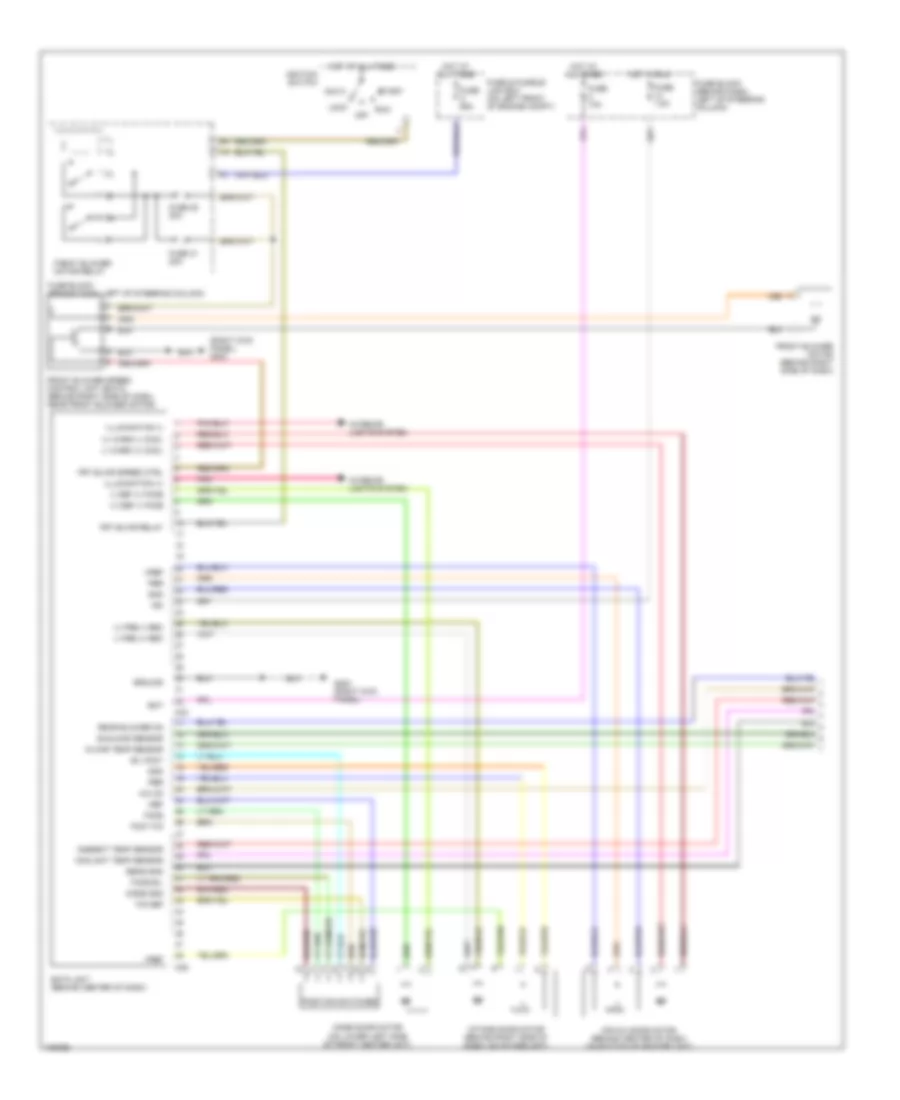
AIR CONDITIONING Automatic A/C Wiring Diagram (1 of 2) for Nissan Quest GLE 2001 List of elements for Automatic A/C Wiring Diagram (1 of 2) for Nissan Quest GLE 2001: 59 (+) def (-) face (+) fre (-) rec (+) warm (-) cool (-) def (+) face (-) fre (+) rec (-) warm (+) cool (right kick panel) g203 A/c on Acc Air mix door motor (behind center of dash, on bottom of heater unit) Ambient temp sensor B/l foot Bat Coolant temp sensor Def Eatc unit (behind center of dash) F/d def Face Face b/l Foot f/d Front blower motor (behind right side of dash) Front blower motor relay Front blower speed control unit (eatc) (behind right side of dash, near front blower motor) Frt blwr relay Frt blwr speed ctrl Fuse & fusible link box (on left front of engine compt) Fuse 10a Fuse 28 20a Fuse 31 20a Fuse 7.5a Fuse block (behind dash, left of steering column) Fuse c 65a G203 (right kick panel) Gnd Ground Hot at all times Hot in run Ign Ignition switch Illumination (+) Illumination (-) In car temp sensor Intake door motor (behind right side of dash, on intake unit) Interior lights system Lock M33 M35 Mode door motor (on lower left side of front heater unit) Mode gnd Off Pbr Pnk Position switches Rear blower on Run Sens gnd Start Sunload sensor Vref Automatic A/C Wiring Diagram (2 of 2) for Nissan Quest GLE 2001 List of elements for Automatic A/C Wiring Diagram (2 of 2) for Nissan Quest GLE 2001: 44 A/c compressor A/c rly Air conditioner relay (on relay box) Ambient temperature sensor (in front of radiator support) Arcon Cooling fan motor Cooling fan relay 1 Cooling fan relay 2 Cooling fan relay 3 Diode 3 (at front of engine, near a/c compressor) Ecm (behind right side of dash) Engine coolant ambient temperature sensor (eatc) (on center rear of engine compt) Fuse & fusible link box (on left front of engine compt) Fuse 10a Fuse 15a Fuse block (behind dash, left of steering column) Fuse j 75a Fuse l 20a G116 (left side of firewall) G134 (top of engine) G200 (left kick panel) G203 (right kick panel) High pressure switch (on a/c compressor manifold) Hot at all times Hot in run or start In-vehicle temperature sensor (eatc) (behind dash, right of steering column) Interior lights system J/c 4 Low pressure switch (on right side of engine compt, on a/c accumulator) Nca Not used Off Pdsw Pnk Radh Radl Rear Rear blower motor (at right side of cargo compt) Rear blower motor relay (eatc) (at left side of front passenger's footwell) Rear blower motor resistor (at right side of cargo compt, near rear blower motor) Rear fan switch (front) Rear fan switch (rear) Red Sunload sensor (eatc) (on top of dash, on left defroster grille) Manual A/C Wiring Diagram (1 of 2) for Nissan Quest GLE 2001 List of elements for Manual A/C Wiring Diagram (1 of 2) for Nissan Quest GLE 2001: 63 (+) ill (+) rec (-) fre (-) ill (-) rec (+) fre (right kick panel) g203 A/c compressor A/c control unit A/c on Ac rly Acc Air conditioner relay (on relay box) Air mix Air mix door motor (behind center of dash, on bottom of heater unit) Arcon Cooling fan motor Cooling fan relay 1 Cooling fan relay 2 Cooling fan relay 3 Diode 3 (at front of engine, near a/c compressor) Ecm (behind right side of dash) Front blower motor (behind right side of dash) Front blower motor relay Front blower motor resistor (behind right side of dash, near front blower motor) Front fan switch Frt blw relay cont Fuse & and fusible link box (on left front of engine compt) Fuse & fusible link box (on left front of engine compt) Fuse 10a Fuse 28 20a Fuse 31 20a Fuse 7.5a Fuse block (behind dash, left of steering column) Fuse c 65a Fuse j 75a Fuse l 20a G116 (left side of firewall) G134 (top of engine) G200 (left kick panel) G203 (right kick panel) High pressure switch (on a/c compressor manifold) Hot at all times Hot in run Hot in run or start Ign Ignition switch Intake door motor (behind right side of dash, on intake unit) Interior lights system J/c 4 (in fuse & fusible link box) Lock Low pressure switch (on right side of engine compt, on a/c accumulator) Mode Mode door motor (on lower left side of front heater unit) Nca Not used Off Pdsw Pnk Radh Radl Run Start Temperature control switch With rear a/c Manual A/C Wiring Diagram (2 of 2) for Nissan Quest GLE 2001 List of elements for Manual A/C Wiring Diagram (2 of 2) for Nissan Quest GLE 2001: 14 Fuse 15a Fuse block (behind dash, left of steering column) G200 (left kick panel) Hot at all times Interior lights system Off Pnk Rear Rear blower motor (at right side of cargo compt) Rear blower motor resistor (at right side of cargo compt, near rear blower motor) Rear fan switch (front) Rear fan switch (rear) Rear fan switch relay 1 (at left side of front passenger's footwell) Red
ANTI-LOCK BRAKES Anti-lock Brake Wiring Diagrams for Nissan Quest GLE 2001 List of elements for Anti-lock Brake Wiring Diagrams for Nissan Quest GLE 2001: 51 Abs actuator Abs actuator & electric unit (left side of engine compt) Abs control unit Abs lamp Abs warning lamp Combination meter Data link connector (consult) (under left dash panel, near fuse box cover) Diag l Diode 1 (abs) (behind left side of dash) Fl in Fl out Fl ss(+) Fl ss(-) Fr in Fr out Fr ss(+) Fr ss(-) Fuse & fusible link box (left front of engine compt) Fuse 10a Fuse block (left of steering column) Fuse g 40a Fuse h 20a G100 (front of left front fender) Gnd Hot at all times Hot in on or start Ign Left front wheel speed sensor (on wheel spindle assembly) Left rear wheel speed sensor (on wheel spindle assembly) Motor Motor relay Mtr rly Pnk Red Relay unit Right front wheel speed sensor (on wheel spindle assembly) Right rear wheel speed sensor (on wheel spindle assembly) Rl in Rl out Rl ss(+) Rl ss(-) Rr in Rr out Rr ss(+) Rr ss(-) Rxd Sol rly Solenoid valve relay Stop Stoplight switch (on bracket, above brake pedal) Txd
ANTI-THEFT Anti-theft Wiring Diagram (1 of 2) for Nissan Quest GLE 2001 List of elements for Anti-theft Wiring Diagram (1 of 2) for Nissan Quest GLE 2001: 60 (left kick panel) g200 Acc Back dr latch sw Back dr unlk sen Battery Circuit breaker 1 (behind left kick panel) Door key lk sw Dr key unlk sw Exterior lights system Fuse & fusible link box (on left front of engine compt) Fuse 23 10a Fuse 30 10a Fuse 39 7.5a Fuse 5 7.5a Fuse block (left of steering column) G116 (left side of firewall) G203 (right kick panel) G402 (left rear wheelwell) Ground Headlamps Headlights system Horn relay Horns system Hot at all times Hot in on or acc Hot in on or start Ignition J/c 4 (in fuse & fusible link box) Key switch Left back door latch switch Left door sw Left front door switch Left sliding door switch Lock Lock input Lock output Lt fr dr unlk out Lt fr unlk sen Main power window & door lock/ unlock switch Memory out Memory systems Red Right back door latch switch Right door lock/ unlock switch Right door sw Right front door switch Right sliding door switch Rt fr unlk sen Security indicator lamp Security lamp Sliding dr lk out Sliding dr sw Smart entrance control unit (behind center of dash) Starter cut Starting/charging system Taillight relay Theft warning relay (on relay box) Unlk Unlock input Unlock output Anti-theft Wiring Diagram (2 of 2) for Nissan Quest GLE 2001 List of elements for Anti-theft Wiring Diagram (2 of 2) for Nissan Quest GLE 2001: 15 Back door key cylinder switch Back door lock actuator G200 (left kick panel) G203 (right kick panel) G402 (left rear wheelwell) Left front door key cylinder switch Left front door lock actuator Left sliding door lock actuator Lock Red Right front door lock actuator Right sliding door lock actuator Sliding door contact switches Unlk Unlock
BODY COMPUTER Body Computer Wiring Diagrams for Nissan Quest GLE 2001 List of elements for Body Computer Wiring Diagrams for Nissan Quest GLE 2001: 62 Acc Anti-theft system Back dr latch sw Back dr unlk sen Battery Belt buckle sw Circuit breaker (behind left kick panel) Defogger system Door locks system Dr ajar warn lp Dr key cly lock Dr key cyl unlk Exterior lights system Fuse & fusible link box (left front of engine compt) Fuse 10a Fuse 7.5a Fuse block (behind dash, left of steering column) Fuse f 30a G203 (right kick panel) Ground Headlamp Headlights system Horn relay Horns system Hot at all times Hot in on or acc Hot in on or start Ignition Ill control out Ill ctrl sw Illum ctrl sw Instrument cluster system Int lt signal Interior lights system Key switch L fr dr unlk out L fr unlock sen Left door sw Lock Lock out Mem seat out Memory system Pnk Power windows system Pwr window relay R fr unlock sen Red Right door sw Room lamp zone a Room lamp zone b Room lamp zone c Rr wd defog rly Rr wd defog sw Security lamp Sldg dr unlk sen Sliding dr sw Smart entrance control unit (behind center of dash) Taillight relay Theft warning rly Unlock Unlock out Warning systems
COMPUTER DATA LINES Computer Data Lines for Nissan Quest GLE 2001 List of elements for Computer Data Lines for Nissan Quest GLE 2001: 27 Abs actuator & electric unit (on left side of engine compt) Air bag diagnosis sensor unit (at right side of driver's footwell) Cdcv Check Data link connector (dlc) (under left dash panel, near fuse box cover) Diag l Engine control module (ecm) (behind right side of dash) Evap canister vent control valve (near fuel tank, on evap canister) Fuse & fusible link box (left front of engine compartment) Fuse 29 10a Fuse 34 10a Fuse 4 10a Fuse block (behind dash, left of steering column) G134 (top of engine) G200 (left kick panel) G203 (right kick panel) G402 (left rear wheelwell) Gnd c Hot at all times Hot in on or start Kline Red Rxd Scirx Scitx Transmission control module (tcm) (behind dash, right of steering column) Txd
COOLING FAN Cooling Fan Wiring Diagram for Nissan Quest GLE 2001 List of elements for Cooling Fan Wiring Diagram for Nissan Quest GLE 2001: 21 Cooling fan motor Cooling fan relay 1 (on fuse & fusible link box) Cooling fan relay 2 (on fuse & fusible link box) Cooling fan relay 3 (on fuse & fusible link box) Engine control module (ecm) (behind right side of dash) Fuse & fusible link box (left front of engine compt) Fuse 10a Fuse block (behind dash, left of steering column) Fuse j 75a Fuse l 20a G116 (left side of firewall) G134 (top of engine) High pressure switch (at front of engine, on a/c compressor manifold) Hot at all times Hot in on or start Joint connector 4 (in fuse & fusible link box) Nca Not used Pdsw Radh Radl
CRUISE CONTROL Cruise Control Wiring Diagram for Nissan Quest GLE 2001 List of elements for Cruise Control Wiring Diagram for Nissan Quest GLE 2001: 45 (center rear of dash) g206 (right kick panel) g203 (starting circuit) starting/charging system Air valve Ascd 4th cut sw Ascd actuator Ascd brake switch (on bracket, above brake pedal) Ascd control unit (at right side of driver's footwell) Ascd cruise switch Ascd steering switch Brake nc sw Brake no sw Cancel switch Combination meter Command gnd Command sw Cruise Cruise lamp Cruise on/off switch Cruise signal Fuse 22 20a Fuse 29 10a Fuse block (behind dash, left of steering column) Ground Hot at all times Hot in on or start Ignition M16 M17 Od cancel Park/neutral position relay (on relay box) Pump power Red Release valve Resume/ accel switch Set Set lamp Set/ coast switch Speed- ometer Spiral cable Stoplight switch (on bracket, above brake pedal) Transmission control module (tcm) (behind dash, right of steering column) Vacuum valve Vehicle speed sensor (on transaxle) Vss
DEFOGGERS Defogger Wiring Diagram for Nissan Quest GLE 2001 List of elements for Defogger Wiring Diagram for Nissan Quest GLE 2001: 27 Acc Fuse 10a Fuse 20a Fuse and fusible link box (on left front of engine compt) Fuse block (behind dash, left of steering column) Fuse i 45a G200 (left kick panel) G203 (right kick panel) G402 (left rear wheelwell) G998 (right "d" pillar) Hot at all times Hot in on or start Ignition switch Illum Indicator Interior lights system Left door mirror defogger Nca Off On ign2 Pnk Rear window defogger Rear window defogger relay Rear window defogger switch Right door mirror defogger Smart entrance control unit (behind center of dash) Start
ENGINE PERFORMANCE
3.3L 3.3L, Engine Performance Wiring Diagrams (1 of 3) for Nissan Quest GLE 2001 List of elements for 3.3L, Engine Performance Wiring Diagrams (1 of 3) for Nissan Quest GLE 2001: 71 (13-16, 40-41, 51-53 not used) (behind right side of dash) ecm relay (on throttle body) throttle position sensor (under left dash panel, near fuse block cover) data link connector (dlc) A/c system Absolute pressure sensor (left side of firewall) Acrly Arcon Atck Avcc Check Cooling fans system Crankshaft position sensor (on transaxle housing) Dt1 Dt2 Dt3 Engine control module (ecm) (behind right side of dash) Engine coolant temperature sensor (in intake manifold) Evap control system pressure sensor (at fuel tank) Evp1 Fpr Ftpres Fuel flow Fuel tank temperature sensor (fuel tank gauge unit) Fuse & fusible link box (left front of engine compt) Fuse 10a Fuse 7.5a Fuse block (behind dash, left of steering column) G134 (top of engine) Gnd-a Gnd-c Gnd-i Hot at all times Hot in on or start Hot in start Idle Ign Ignck Ignsw Instrument cluster system (fuel flow) Intake air temperature sensor (in air duct housing) Kline Knk Knock sensor (top of engine) Led-r Mass air- flow sensor (on air intake assembly) Neut O2sf O2sr Pdsw Pnk Pos Pres Pwst Qa+ Qa- Radh Radl Red Ref Rfanck1 Rfanck2 Rgc/s Ssoff Stsw Tacho Tamb Tfuel Tvo1 Tvoo Vsp 3.3L, Engine Performance Wiring Diagrams (2 of 3) for Nissan Quest GLE 2001 List of elements for 3.3L, Engine Performance Wiring Diagrams (2 of 3) for Nissan Quest GLE 2001: 30 (behind left kick panel) inertia fuel shutoff switch (in fuse & fusible link box) j/c 4 (left side of transaxle) park/neutral position switch (on relay box) fuel pump relay (on throttle body) throttle position switch Acc Camshaft position sensor Closed Condenser Distributor Evap canister purge volume control solenoid valve (right side of engine, on intake manifold collector) Fuel pump (fuel tank gauge unit) Fuse & fusible link box (left front of engine compt) Fuse 10a Fuse 15a Fuse block (behind dash, left of steering column) G134 (top of engine) G200 (left kick panel) Hot at all times Hot in on or start Ignition coil Ignition switch Nca Off Pnk Power steering oil pressure switch (on right rear corner of engine compt) Power transistor Resistor (on right front of engine, near distributor) Start Transmission control module (tcm) (behind dash, right of steering column) 3.3L, Engine Performance Wiring Diagrams (3 of 3) for Nissan Quest GLE 2001 List of elements for 3.3L, Engine Performance Wiring Diagrams (3 of 3) for Nissan Quest GLE 2001: 39 (77-79 not used) (center rear of dash) g206 1o1 Abc sol Batt Cdcv Combination meter Crtn Cvbv Engine control module (ecm) (behind right side of dash) Evap canister vent control valve (near fuel tank, on evap canister) Front heated oxygen sensor (front of catalytic converter) Fuel injectors Fuse & fusible link box (left front of engine compt) Fuse 10a Fuse 7.5a Fuse block (behind dash, left of steering column) G134 (top of engine) Gnd-e Hot at all times Hot in on or start Iacv-aac valve (on top right side of engine) Inj 1 Inj 2 Inj 3 Inj 4 Inj 5 Inj 6 Isc Malfunction indicator lamp Map/baro switch solenoid valve (top rear of engine) Nca O2hf O2hr Rear heated oxygen sensor (on exhaust, near catalytic converter) Scirx Scitx Vacuum cut valve by-pass valve (between fuel tank & evap canister) Vehicle speed sensor (on transaxle)
EXTERIOR LIGHTS Back-up Lamps Wiring Diagram for Nissan Quest GLE 2001 List of elements for Back-up Lamps Wiring Diagram for Nissan Quest GLE 2001: 8 Fuse 10a Fuse block (behind dash, left of steering column) G402 (left rear Hot in run or start Left back-up lamp Park/neutral position switch (on left side of transaxle) Right back-up lamp Wheelwell) Exterior Lamps Wiring Diagram (1 of 2) for Nissan Quest GLE 2001 List of elements for Exterior Lamps Wiring Diagram (1 of 2) for Nissan Quest GLE 2001: 35 Combination flasher unit (behind left side of dash) Combination switch 2 (turn signal switch) Combinaton meter Fuse 23 10a Fuse 27 10a Fuse block (behind dash, left of steering column) G105 (rear of right front fender) G116 (left side of firewall) G203 (right kick panel) G402 (left rear G403 (right rear Ground Hazard switch Hot at all times Hot in start or run Illumination lamp Interior lights system Joint connector 4 (in fuse and fusible link box) Left Left front turn signal lamp Left rear combination lamp Left turn ind M16 Off Out Pnk Power Right Right front turn signal lamp Right rear combination lamp Right turn ind Stop Tail Turn Wheelwell) Exterior Lamps Wiring Diagram (2 of 2) for Nissan Quest GLE 2001 List of elements for Exterior Lamps Wiring Diagram (2 of 2) for Nissan Quest GLE 2001: 30 1st 2nd Combin- ation switch (corner- ing lamp switch) Fuse & fusible link box (left front of engine compt) Fuse 10a Fuse 20a Fuse a 100a Fuse block (behind dash, left of steering column) G105 (rear of right front fender) G116 (left side of firewall G200 (left kick panel) G402 (left rear wheelwell) Headlamp control unit (at right side of driver's footwell) High mounted stop lamp Hot at all times Joint connector 4 (in fuse & fusible link box) Left front combination lamp Left front side marker lamp Left license lamp Left right Lighting switch Off Right front combination lamp Right front side marker lamp Right license lamp Stop- light switch (above brake pedal) Tail lamp Taillight relay Trailer towing circuit W/ autolamp Trailer Tow Wiring Diagram for Nissan Quest GLE 2001 List of elements for Trailer Tow Wiring Diagram for Nissan Quest GLE 2001: 18 B203 Battery Exterior lights system Exterior lights system (taillight relay) Fuse 22 20a Fuse block (behind dash, left of steering column) G402 (left rear wheelwell) Ground Hot at all times Left stop/turn Left turn sig M125 Right turn sig Rt stop/turn Stop Stoplight switch (on bracket, above brake pedal) Trailer tow connector (behind center of rear bumper) Trailer tow control unit (at left side of cargo compartment)
GROUND DISTRIBUTION Ground Distribution Wiring Diagram for Nissan Quest GLE 2001 List of elements for Ground Distribution Wiring Diagram for Nissan Quest GLE 2001: 31 Audio unit, cd changer, video monitor, video cassette player, family entertainment system control panel Combination meter, Cooling fan motor Data link connector, evap control system pressure sensor, heated oxygen sensor 2 (rear) (shield), heated oxygen sensor 2 (rear), distributor, camshaft position sensor, resistor (ignition coil) (shield), engine control module (ecm), heated oxygen sensor 1 (front) (shield), throttle position sensor, absolute pressure sensor, mass air flow sensor, transmission control module (tcm), crankshaft position sensor (shield), knock sensor (shield) Diode 1 (w/o abs), front wiper amplifier, cooling fan motor, fuse block (accessory & ignition relays), a/t device. combination switch Distributor, high pressure switch, engine control module (ecm) Door mirror remote control switch, left front door key cylinder switch, left front door lock actuator, main power window & door lock/unlock switch, left power seat switch, left front heated seat Front wiper amplifier, front side marker lamp, left front combination lamp, left headlamp, left front turn signal lamp, park/neutral (pnp) position relay, bulb check relay, abs actuator & electric unit, brake fluid level switch, front wiper motor, key switch, overdrive control switch G100 (front of left front fender) G104 (rear of left front fender) G105 (rear of right front fender) G116 (left side of firewall) G134 (top of engine) G200 (left kick panel) G203 (right kick panel) G206 (center rear of dash) G402 (left rear wheelwell) G403 (right rear wheelwell) G998 (right "d" pillar) Generator High mounted stop lamp, glass hatch latch switch, back door key cylinder switch, left back-up lamp, license lamps, back door left latch switch, right back-up lamp, rear wiper motor, back door lock actuator, back door latch switch Illumination control switch, combination flasher unit, data link connector, combination meter, rear wiper switch, rear window defogger switch, rear wiper switch, cigarette lighter socket, eatc unit, a/c control unit, Lighting switch, headlamp control unit, front fan switch, rear fan switch, front blower motor resistor, inertia fuel shutoff switch, left front door switch, rear audio remote control unit, seat belt buckle switch, memory seat & mirror control unit, integrated homelink transmitter, left vanity lamp, right vanity lamp, sunroof switch, memory set switch, left door mirror, Rear fan switch relay, ascd control unit, front blower speed control unit, mix door actuator, mode door actuator, left rear power point, right rear power point, a/c compressor, diode 3, iacv-ficd solenoid valve, Rear power point, trailer tow connector, trailer tow control unit, left rear combination lamp, fuel level sensor unit, subwoofer amplifier Rear window defogger Right door mirror, right door lock/unlock switch, right front door lock actuator, air bag diagnosis sensor unit, horn switch Right front turn signal lamp, right headlamp, right front combination lamp, right front side marker lamp, washer fluid level switch, left front fog lamp, right front fog lamp, outside air temperature sensor, front fog lamp switch Right rear combination lamp, right power seat switch, right heated seat switch Smart entrance control unit, Vehicle speed sensor
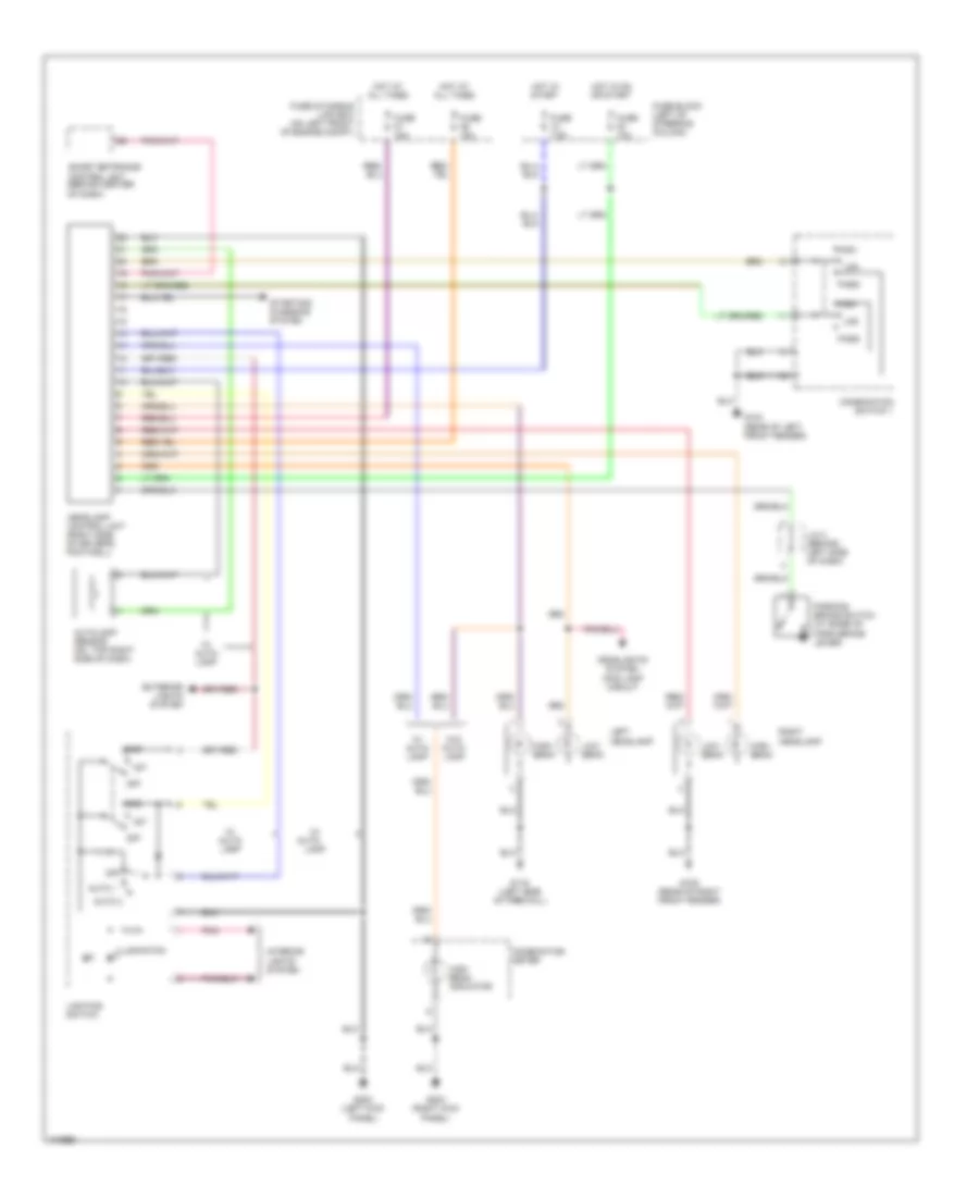
HEADLIGHTS Fog Lamp Wiring Diagram for Nissan Quest GLE 2001 List of elements for Fog Lamp Wiring Diagram for Nissan Quest GLE 2001: 16 7.5a Fog lamp switch Foglamp relay Fuse Fuse & fusible link box (on left front of engine compt) G105 (rear of right front fender) Headlamp control module (right side of driver's footwell) Hot at all times Illumination Interior lights system Left fog lamp Left headlamp On ind Pnk Relay box (left front front corner of engine compt) Right fog lamp Headlight Wiring Diagram, with DRL for Nissan Quest GLE 2001 List of elements for Headlight Wiring Diagram, with DRL for Nissan Quest GLE 2001: 44 1st 2nd Auto 1 Auto 2 Auto- Autolamp sensor (on top right side of dash) Combination meter Combination switch 1 Exterior lights system Fuse & fusible link box (on left front of engine compt) Fuse 10a Fuse 15a Fuse 7.5a Fuse block (left of steering column) G104 (rear of left front fender) G105 (rear of right front fender) G116 (left side of firewall) G200 (left kick panel) G203 (right kick panel) Headlamp control unit (right side of driver's footwell) Headlights system (fog lamp circuit High High beam High beam indicator Hot at all times Hot in on or start Hot in start Illuminaton Interior lights system J/c 2 (behind left side of dash) Lamp Left headlamp Lighting switch Low Low beam Off Parking brake switch (at base of park brake lever) Pass Pnk Right headlamp Smart entrance control unit (behind center of dash) Starting/ charging system W/ auto- lamp W/o auto- lamp Headlight Wiring Diagram, without DRL, with Autolamps for Nissan Quest GLE 2001 List of elements for Headlight Wiring Diagram, without DRL, with Autolamps for Nissan Quest GLE 2001: 35 1st 2nd Auto 1 Auto 2 Autolamp sensor (on top right side of dash) Combination meter Combination switch 1 Exterior lights system Fuse & fusible link box (on left front of engine compt) Fuse 10a Fuse 15a Fuse block (left of steering column) G104 (rear of left front fender) G105 (rear of right front fender) G116 (left side of firewall) G200 (left kick panel) G203 (right kick panel) Headlamp control unit (right side of driver's footwell) Headlights system (fog lamp circuit) High High beam High beam indicator Hot at all times Hot in on or start Illuminaton Interior lights system Left headlamp Lighting switch Low Low beam Off Pass Pnk Right headlamp Smart entrance control unit (behind center of dash) Headlight Wiring Diagram, without DRL, without Autolamps for Nissan Quest GLE 2001 List of elements for Headlight Wiring Diagram, without DRL, without Autolamps for Nissan Quest GLE 2001: 29 1st 2nd Combination meter Combination switch 1 Exterior lights system Fuse & fusible link box (on left front of engine compt) Fuse 15a G104 (rear of left front fender) G105 (rear of right front fender) G116 (left side of firewall) G202 (left side of dash) G203 (riight kick panel) Headlamp control unit (right side of driver's footwell) Headlights system (fog lamp circuit) High High beam High beam indicator Hot at all times Illuminaton Interior lights system Left headlamp Lighting switch Low Low beam Off Pass Pnk Right headlamp Smart entrance control unit (behind center of dash)
HORN Horn Wiring Diagram for Nissan Quest GLE 2001 List of elements for Horn Wiring Diagram for Nissan Quest GLE 2001: 12 15a Fuse & fusible link box (left front of engine compt) Fuse 42 G201 (right side of dash) High horn Horn relay Horn switch Hot at all times Low horn Red Relay box (left front corner of engine compt) Spiral cable
INSTRUMENT CLUSTER Instrument Cluster Wiring Diagram (1 of 2) for Nissan Quest GLE 2001 List of elements for Instrument Cluster Wiring Diagram (1 of 2) for Nissan Quest GLE 2001: 50 (left rear wheelwell) (right kick panel) g203 Abs indicator Air bag diagnostic sensor unit (at right side of driver's footwell) Air bag indicator Automatic speed control device (at right side of driver's footwell) Brake indicator Charge indicator Combination meter Cruise indicator Door indicator Engine control module (ecm) (behind right side of dash) Exterior lights system Fuel gauge Fuel gauge sender Fuel indicator Fuel level sensor unit Fuse 10a Fuse box G206 (center rear of dash) G402 Headlights system Hi beam indicator Hot at all times Hot in start or run Interior lights system Lcd illumination (3 gray bulbs) Left turn indicator M16 M17 M39 Message center Meter illumination (4 white bulbs) Mil indicator O/d off indicator Oil indicator Oil pressure switch (at lower left front of engine, at base of oil filter) Pnk Red Right turn indicator Seatbelt indicator Set indicator Smart entrance control unit (behind center of dash) Speedometer Tachometer Thermal transmitter (on top right of engine) Transaxle control module (tcm) (behind dash, right of steering column) Vehicle speed sensor (on transaxle) Washer indicator Water temper- ature gauge Instrument Cluster Wiring Diagram (2 of 2) for Nissan Quest GLE 2001 List of elements for Instrument Cluster Wiring Diagram (2 of 2) for Nissan Quest GLE 2001: 22 (in brake fluid reservoir) (left kick panel) (on washer fluid reservoir) Abs actuator & Brake fluid level switch Bulb check relay Diode 1 (behind left side of dash) E22 Electric unit (at left side of engine compt) G105 (rear of right front fender) G116 (left rear of engine compt) G200 Generator J/c 2 (behind left side of dash) J/c 4 (in fuse & fusible link box) M39 Parking brake switch (at base of park brake lever) Pnk Relay box (at left front corner of engine compt) Seat belt buckle switch (on driver's seat belt buckle) Smart entrance control unit (behind center of dash) Washer fluid level switch
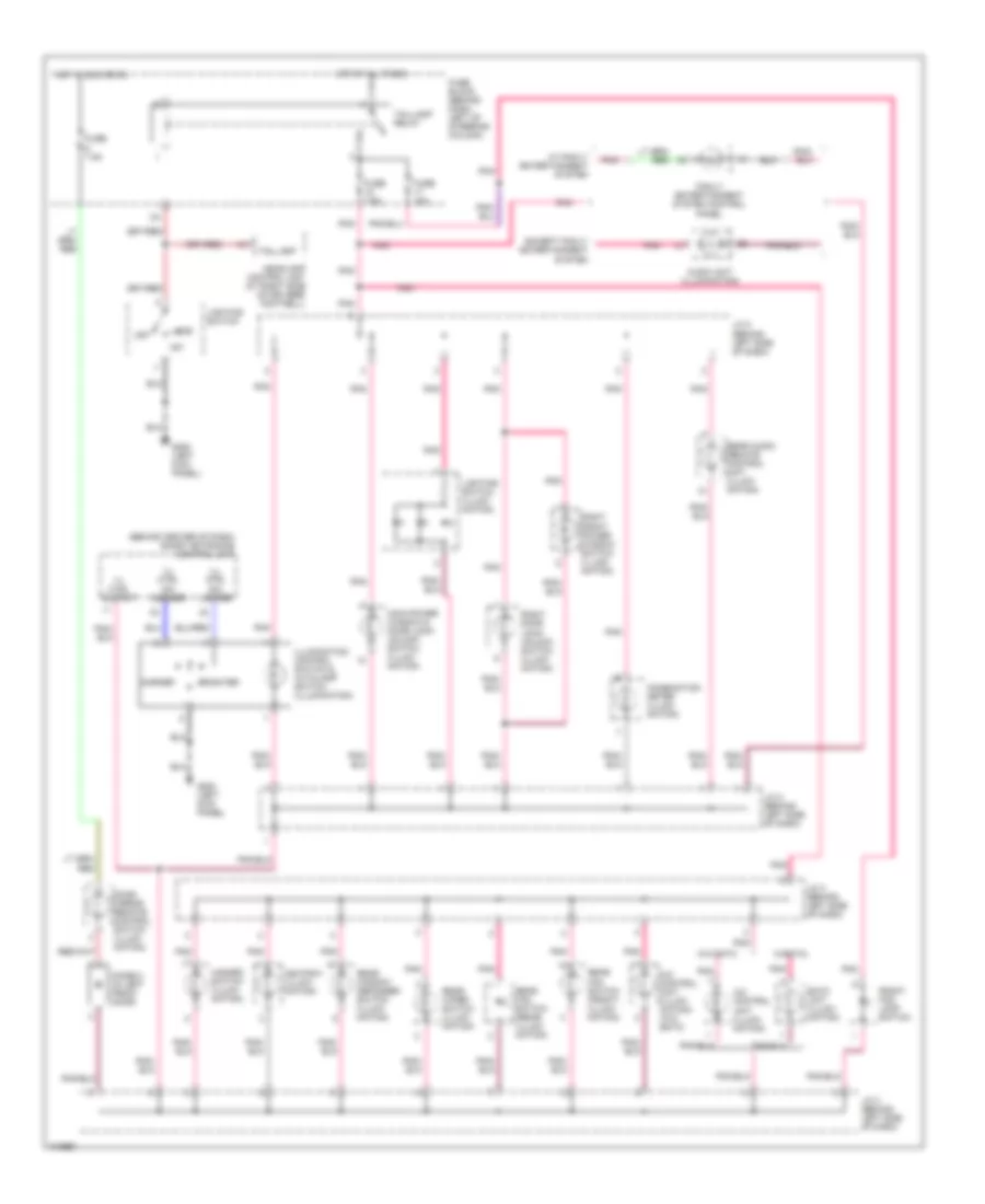
INTERIOR LIGHTS Courtesy Lamps Wiring Diagram for Nissan Quest GLE 2001 List of elements for Courtesy Lamps Wiring Diagram for Nissan Quest GLE 2001: 45 Back door lamp Back door latch switches Closed Door Front personal lamp Front room lamp Fuse 15a Fuse block (behind dash, left of steering column) G116 (left side of firewall) G200 (left kick panel) G402 (left rear wheelwell) Glove box lamp Hot at all times Interior lighting signal J/c 3 (behind left side of dash) J/c 4 (in fuse & fusible link box, left front of eng compt) Key switch Left back door latch switch Left door switch Left foot lamp Left front door switch Left front step lamp Left sliding door step lamp Left sliding door switch Left vanity lamp Lighting switch Map lamp Off Open Rear personal lamp Rear room lamp Red Right back door latch switch Right door switch Right foot lamp Right front door switch Right front step lamp Right sliding door step lamp Right sliding door switch Right vanity lamp Room lamp zone a Room lamp zone b Room lamp zone c Sliding door switches Smart entrance control unit (behind center of dash) Instrument Illumination Wiring Diagram for Nissan Quest GLE 2001 List of elements for Instrument Illumination Wiring Diagram for Nissan Quest GLE 2001: 47 (behind center of dash) smart entrance control unit 1st 2nd A/c control unit (illumi- nation) A/c control unit (illumi- nation) (w/o eatc) Ashtray (illumi- nation) Audio unit (illumination) Brighter Combination meter (illumi- nation) Darker Diode 2 (in left front door) Door mirror remote control switch (illumi- nation) Eatc unit (illumi- nation) Except family entertainment system Family entertainment system control panel Front fog lamp switch Fuse 10a Fuse 7.5a Fuse block (behind dash, left of steering column) G200 (left kick panel) Hazard switch (illumi- nation) Headlamp control unit (at right side of driver's footwell) Hot at all times Hot in acc or on Ill ctrl output Ill ctrl sw darker Ill ctrl sw lighter Illumination control switch & autolamp switch (illumination) J/c 2 (behind left side of dash) J/c 3 (behind left side of dash) Lighting switch Lighting switch (illumi- nation) Main power window & door lock/ unlock switch (illumi- nation) Off Pnk Rear audio remote control unit (illumi- nation) Rear fan switch (front) (illumi- nation) Rear fan switch (rear) (illumi- nation) Rear window defogger switch (illumi- nation) Rear wiper switch (illumi- nation) Right door lock/ unlock switch (illumi- nation) Right front power window switch (illumi- nation) Taillamp Taillamp relay W/ family entertainment system W/eatc W/o eatc
MEMORY SYSTEMS Memory Mirrors Wiring Diagram for Nissan Quest GLE 2001 List of elements for Memory Mirrors Wiring Diagram for Nissan Quest GLE 2001: 33 (left side of dash) g202 (on left front of engine compt) Circuit breaker 2 (behind left kick panel) D105 D106 Defogger system Direct- tional switch Door mirror remote control switch Fuse & fusible link box Fuse 10a Fuse 15a Fuse 7.5a Fuse block (behind dash, left of steering column) Fuse f 30a Heated mirror Hot at all times Hot in on or acc Hot in on or start Interior lights system J/c 3 (behind left side of dash) Left door mirror Left/ right Left/right mirror select switch Memory seat & mirror control unit (under driver's seat) Memory seats system Memory set switch Nca Pnk Right door mirror Set Smart entrance control unit (behind center of dash) Transmissions system Up/ down Memory Seat Wiring Diagram for Nissan Quest GLE 2001 List of elements for Memory Seat Wiring Diagram for Nissan Quest GLE 2001: 28 (left side of dash) g202 Backrest forward/ rearward Circuit breaker 2 (behind left kick panel) Fuse & fusible link box (on left front of engine compt) Fuse 10a Fuse 15a Fuse 30a Fuse block (behind dash, left of steering column) Hot at all times Hot in on or start J/c 3 (behind left side of dash) Left power seat motor assembly Left power seat switch Lifting position sensor Lifting switch Memory mirrors system Memory seat & mirror control unit (under driver's seat) Memory set switch Pnk Reclining position sensor Reclining switch Seat forward/ rearward Seat up/ down Set Sliding position sensor Sliding switch Smart entrance control unit (behind center of dash) Transmissions system
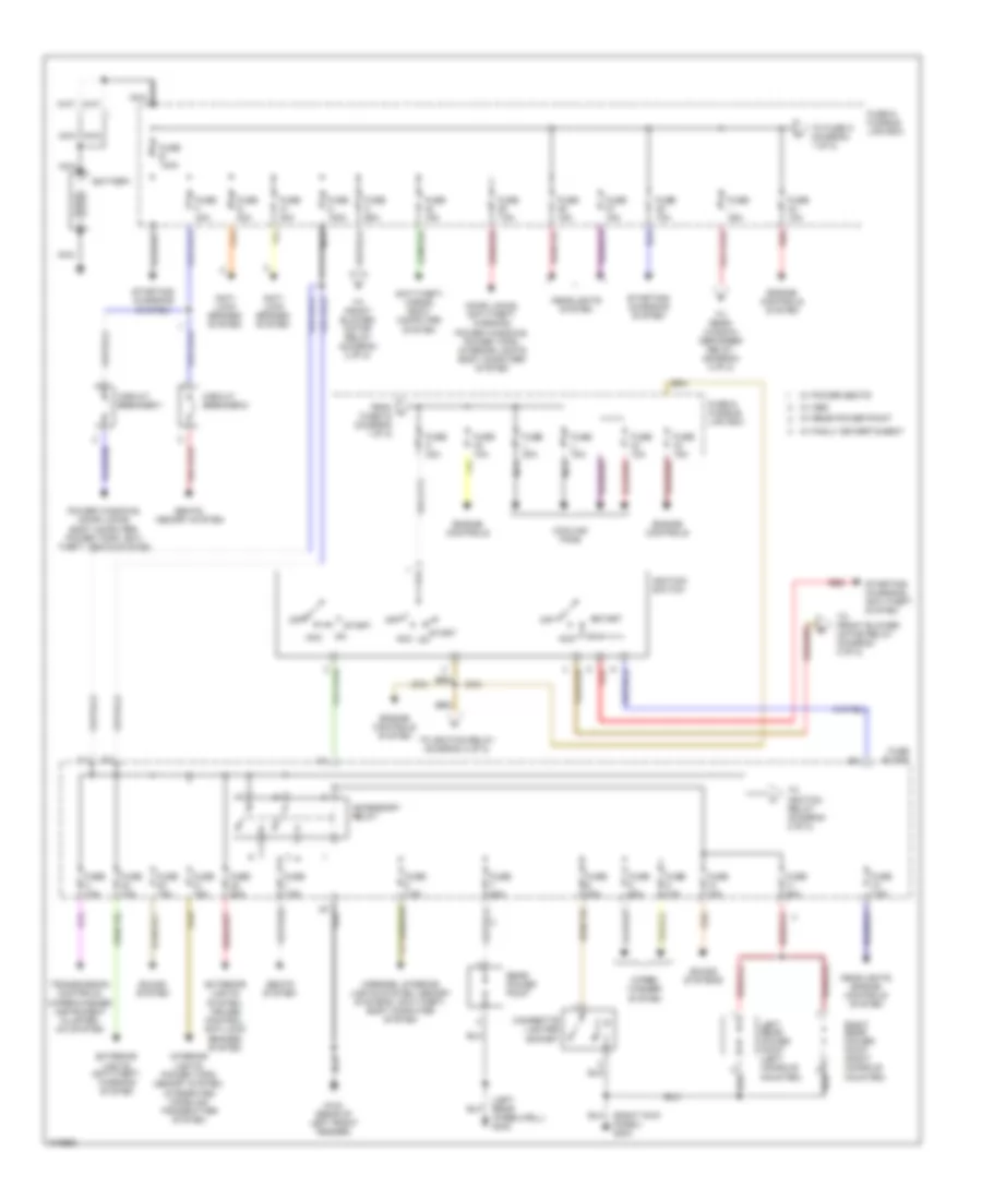
POWER DISTRIBUTION Power Distribution Wiring Diagram (1 of 2) for Nissan Quest GLE 2001 List of elements for Power Distribution Wiring Diagram (1 of 2) for Nissan Quest GLE 2001: 63 (left rear wheelwell) g402 (right kick panel) g203 Acc Accessory relay Anti- lock brakes system Anti-theft, horns, body computer system Battery Cigarette lighter socket Circuit breaker-1 Circuit breaker-2 Cooling fans Door locks, anti-theft, warning, power windows, power tops, interior lights body computer system Engine controls Engine controls system Exterior lights system, cruise control, anti-lock brakes system Exterior lights, anti-theft, warning system From a fuse 34 (diagram 1 of 2) Fuse & fusible link box Fuse 10a Fuse 15a Fuse 20a Fuse 30a Fuse 7.5a Fuse a 100a Fuse b 140a Fuse block Fuse c 65a Fuse f 30a Fuse g 30a Fuse i 45a Fuse j 75a Fuse k 30a Fuse l 20a G104 (rear of left front fender) Headlights system Headlights, engine controls system Ignition switch Interior lights, power tops, memory system, integrated homelink transmitter system Left rear power point (left console mounted) Mirrors, interior lights system, memory systems, anti-theft, body computer system Nca Off Power windows, door locks, body computer, power tops, anti- theft, seats system Rear power point Red Right rear power point (right console mounted) Seats system Seats, memory system Sound system Sound systems Start Starting/ charging system Starting/ charging, anti-theft system To front blower motor relay (diagram 2 of 2) To fuse k (diagram 1 of 2) To ignition relay (diagram 2 of 2) To rear window defogger relay (diagram 2 of 2) Transmission controls, wiper/washer instrument cluster, a/c system W/ abs W/ family entertaiment W/ power seats W/ rear power point Wiper/ washer system Power Distribution Wiring Diagram (2 of 2) for Nissan Quest GLE 2001 List of elements for Power Distribution Wiring Diagram (2 of 2) for Nissan Quest GLE 2001: 41 1st 2nd Air conditioning system Air conditioning, engine controls system Anti-theft system, body computer system Defogger system Engine controls system Engine controls, transmission controls system Exterior lights ststem, anti-theft system Exterior lights system system Exterior lights system, anti-theft system From accessory g From fuse c (diagram 1 of 2) From fuse i (diagram 1 of 2) From ignition switch (diagram 1 of 2) Front blower motor relay Fuse 10a Fuse 13 7.5a Fuse 14 20a Fuse 15 20a Fuse 16 10a Fuse 24 15a Fuse 25 15a Fuse 28 20a Fuse 31 20a Fuse 7.5a Fuse block G104 (rear of left front fender) G200 (left kick panel) Ignition relay Interior lights system Lighting switch Off Pnk Power tops, defogger, mirrors, transmissions, interior lights system, starting/charging, engine controls, anti-theft, headlights, exterior lights system, power windows, warning systems, anti-lock brakes, memory system Rear window defogger relay Red Relay (diagram 1 of 2) Taillight relay W/ auto a/c W/ manual a/c
POWER DOOR LOCKS Power Door Lock Wiring Diagram for Nissan Quest GLE 2001 List of elements for Power Door Lock Wiring Diagram for Nissan Quest GLE 2001: 58 (left kick panel) g200 (left rear wheelwell) g402 (left side of firewall) g116 (right kick panel) g203 Back door key cylinder switch (w/vehicle security system) Back door lock actuator Battery Between full stroke & n Circuit breaker 1 (behind left kick panel) Closed Door key cyl lock sw Door key cyl unlock sw Door unlock sensor Full stroke Fuse & fusible link box (on left front of engine compartment) Fuse 7.5a G200 (left kick panel) G203 (right kick panel) Ground Hot at all times Inserted J/c 4 (in fuse & fusible link box) Key switch Left frnt dr unlock out Left front door key cylinder switch (w/vehicle security system) Left front door lock actuator Left front door switch Left front unlock sens Left sliding door contact switch (left pillar/ door) Left sliding door lock actuator Left sliding door switch Lock Lock output Lock switch Locked M39 M40 Main power window & door lock/ unlock switch Motor Nca Open Red Removed Right door/ lock unlock switch Right front door lock actuator Right front door switch Right front unlock sens Right sliding door contact switch (right pillar/ door) Right sliding door lock actuator Right sliding door switch Sliding door switches Sliding door unlock sens Sliding door/back door Smart entrance control unit (behind center of dash) Un- locked Unlk Unlock Unlock switch
POWER MIRRORS Power Mirror Wiring Diagram for Nissan Quest GLE 2001 List of elements for Power Mirror Wiring Diagram for Nissan Quest GLE 2001: 14 Door mirror remote control switch Fuse 5 7.5a Fuse block (behind dash, left of steering column) G200 (left kick panel) G203 (right kick panel) G402 (left rear wheelwell) Hot in acc or on Illumination Interior lights system Left door mirror Left/right motor Mirror switch Right door mirror Up/down motor
POWER SEATS Heated Seats Wiring Diagram for Nissan Quest GLE 2001 List of elements for Heated Seats Wiring Diagram for Nissan Quest GLE 2001: 18 (left kick panel) Circuit breaker 1 (behind left kick panel) Fuse & fusible link box (on left front of engine compartment) Fuse 7.5a G200 G403 (right rear wheelwell) Hot at all times Ind Left heated seat switch Left seat back heater Left seat cushion heater Off Power window relay (behind left kick panel) Power window relay control Right heated seat switch Right seat back heater Right seat cushion heater Smart entrance control unit (behind center of dash) Power Seat Wiring Diagrams for Nissan Quest GLE 2001 List of elements for Power Seat Wiring Diagrams for Nissan Quest GLE 2001: 18 Circuit breaker 2 (behind left kick panel) Fuse & fusible link box (left front of engine compt) Fuse f 30a G202 (left side of dash) G405 (right rear side of luggage compt) Hot at all times Left power seat switch Left seat motor assembly Lifting motor Lifting switch Pnk Recline switch Reclining motor Red Right power seat switch Right seat motor assembly Sliding motor Sliding switch
POWER TOP/SUNROOF Power Top/Sunroof Wiring Diagrams for Nissan Quest GLE 2001 List of elements for Power Top/Sunroof Wiring Diagrams for Nissan Quest GLE 2001: 25 Batt Circuit breaker 1 (behind left kick panel) Close Closed Fuse & fusible link box (left front of engine compt) Fuse 10a Fuse 15a Fuse 7.5a Fuse block (behind dash, left of steering column) G200 (left kick panel) G203 (right kick panel) Ground Hot at all times Hot in on or start Ign sw Joint con- nector 3 (behind left side of dash) Left door sw Left front door switch Open Power window relay (behind left kick panel) Red Rly ctrl Smart entrance control unit (behind center of dash) Sun roof motor assembly (at front of sun roof opening) Sun roof switch
POWER WINDOWS Power Window Wiring Diagram for Nissan Quest GLE 2001 List of elements for Power Window Wiring Diagram for Nissan Quest GLE 2001: 33 Auto down circuit Circuit breaker 1 (behind left kick panel) Front left Front left power window motor Front right Fuse & fusible link box (on left front of engine compt) Fuse 10a Fuse 7.5a Fuse block (behind dash left of steering column) Fuse f 30a G200 (left kick panel) G203 (right kick panel) Hot at all times Hot in on and start Interior lights system Left front door switch Left rear (w/ rear power vent windows) Leftt rear power vent window motor Lock Lock switch M39 M40 Main power window and door lock/ unlock switch Pnk Power window relay (behind left side of dash) Red Right front door switch Right front power window motor Right front power window switch Right rear (w/ rear power vent windows) Right rear power vent window motor Smart entrance control unit (behind center of dash) Unlock
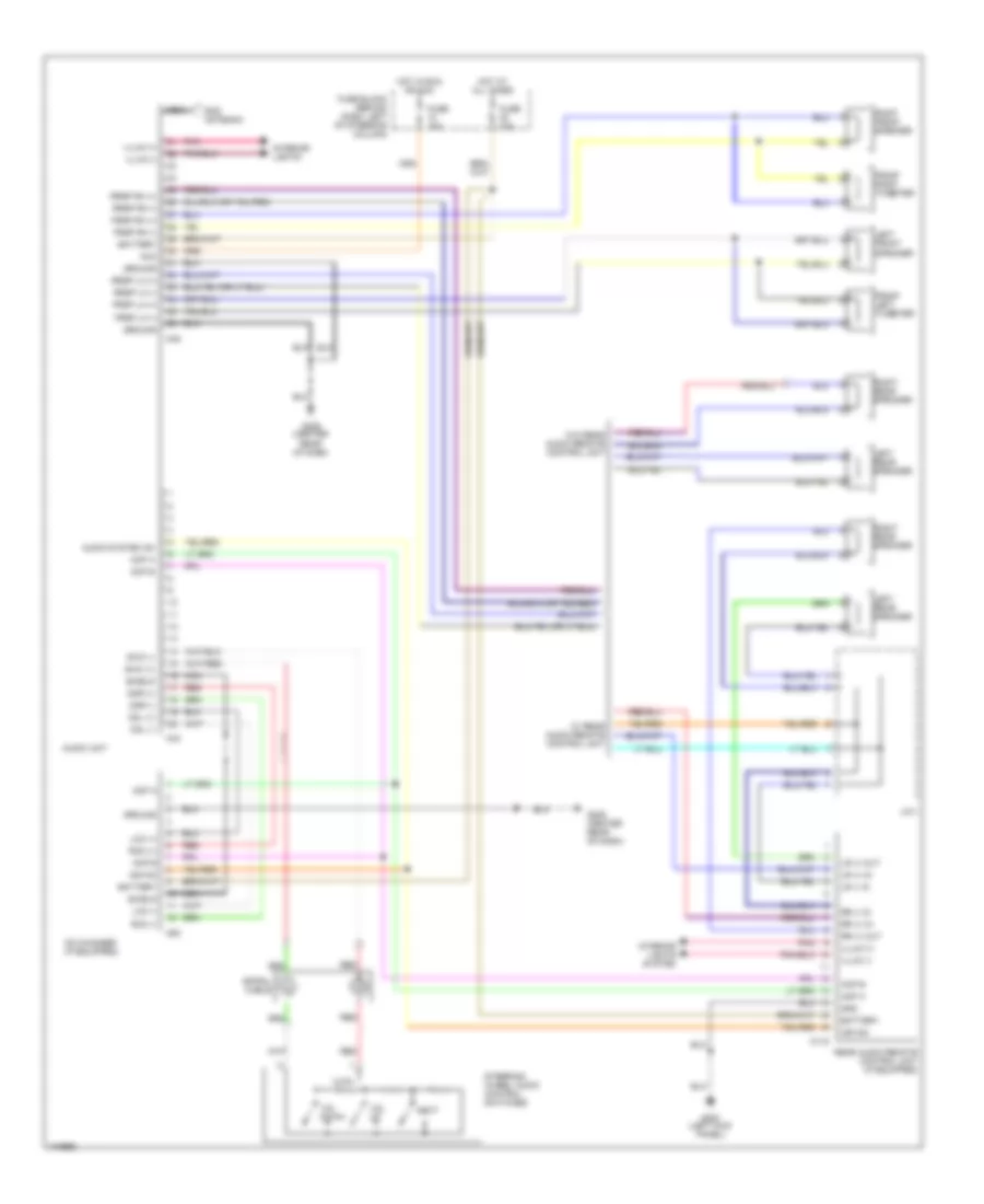
RADIO Radio Wiring Diagrams, Base Radio for Nissan Quest GLE 2001 List of elements for Radio Wiring Diagrams, Base Radio for Nissan Quest GLE 2001: 29 Acc Antenna in Audio unit Battery Frsp lh (+) Frsp lh (-) Frsp rh (+) Frsp rh (-) Fuse 10 15a Fuse 20 10a Fuse block (behind dash, left of steering column) G206 (center rear of dash) Gnd Hot at all times Hot in on or acc Ill (+) Ill (-) Interior lights system Left front door speaker Left rear door speaker Nca Pnk Right front door speaker Right rear door speaker Rod antenna Rrsp lh (+) Rrsp lh (-) Rrsp rh (+) Rrsp rh (-) Radio Wiring Diagrams, Midline with Rear Entertainment Center (1 of 2) for Nissan Quest GLE 2001 List of elements for Radio Wiring Diagrams, Midline with Rear Entertainment Center (1 of 2) for Nissan Quest GLE 2001: 49 (if equipped) Acc Acp a Acp b Asyon Audio system on Audio unit Battery Cd changer (if equipped) Cdl (+) Cdl (-) Cdr (+) Cdr (-) Frsp lh (+) Frsp lh (-) Frsp rh (+) Frsp rh (-) Fuse 10a Fuse 15a Fuse block (behind dash, left of steering column) G206 (center rear of dash) Ground Hot at all times Hot in run or acc Illum (+) Illum (-) Interior lights system Lco (+) Lco (-) M44 M45 M53 Nca Next Pnk Rco (+) Rco (-) Red Rod antenna Rrsp lh (+) Rrsp lh (-) Rrsp rh (+) Rrsp rh (-) Shield Steering wheel audio control switches Swc (+) Swc (-) Vol down Vol up Radio Wiring Diagrams, Midline with Rear Entertainment Center (2 of 2) for Nissan Quest GLE 2001 List of elements for Radio Wiring Diagrams, Midline with Rear Entertainment Center (2 of 2) for Nissan Quest GLE 2001: 47 (center rear of dash) g206 Acc Acp a Acp b Asyon Battery Cddj left (+) Cddj left (-) Cddj right (+) Cddj right (-) Family enter- tainment system control panel Front left tweeter Front right tweeter G206 (center rear of dash) Ground Illum (+) Illum (-) Interior lights system Left front speaker Left rear speaker M307 M308 Nca Pnk Radio left (+) Radio left (-) Radio right (+) Radio right (-) Red Right front speaker Right rear speaker Rrsp lh (+) Rrsp lh (-) Rrsp rh (+) Rrsp rh (-) Screen (+) Screen (-) Shield Vcp control Vcp left (+) Vcp left (-) Vcp right (+) Vcp right (-) Vcp video (+) Vcp video (-) Video cassette player Video monitor Radio Wiring Diagrams, Midline without Rear Entertainment Center for Nissan Quest GLE 2001 List of elements for Radio Wiring Diagrams, Midline without Rear Entertainment Center for Nissan Quest GLE 2001: 69 Acc Acp a Acp b Asyon Audio system on Audio unit Battery Cd changer (if equipped) Cdl (+) Cdl (-) Cdr (+) Cdr (-) Front left tweeter Front right tweeter Frsp lh (+) Frsp lh (-) Frsp rh (+) Frsp rh (-) Fuse 10a Fuse 15a Fuse block (behind dash, left of steering column) G200 (left kick panel) G206 (center rear of dash) Gnd Ground Hot at all times Hot in run or acc Illum (+) Illum (-) Interior lights Interior lights system J/c-1 Lco (+) Lco (-) Left front speaker Left rear speaker Lr (+) in Lr (+) out Lr (-) in M115 M44 M45 M53 Nca Next Pnk Rco (+) Rco (-) Rear audio remote control unit (if equipped) Red Right front speaker Right rear speaker Rod antenna Rr (+) in Rr (+) out Rr (-) in Rrsp lh (+) Rrsp lh (-) Rrsp rh (+) Rrsp rh (-) Shield Spiral cable Steering wheel audio control switches Swc (+) Swc (-) Vol down Vol up W/ rear audio remote control unit W/o rear audio remote control unit Radio Wiring Diagrams, Premium Radio with Rear Entertainment Center (1 of 2) for Nissan Quest GLE 2001 List of elements for Radio Wiring Diagrams, Premium Radio with Rear Entertainment Center (1 of 2) for Nissan Quest GLE 2001: 58 (if equipped) Acc Acp a Acp b Asyon Audio system on Audio unit Battery Cd changer (if equipped) Cdl (+) Cdl (-) Cdr (+) Cdr (-) Frsp lh (+) Frsp lh (-) Frsp rh (+) Frsp rh (-) Fuse 10a Fuse 15a Fuse block (behind dash, left of steering column) G206 (center rear of dash) G402 (left rear wheelwell) Ground Hot at all times Hot in run or acc Illum (+) Illum (-) Input Input (+) Interior lights system Lco (+) Lco (-) M44 M45 M46 M53 Mute input Mute output Nca Next Pnk Rco (+) Rco (-) Red Rod antenna Rrsp lh (+) Rrsp lh (-) Rrsp rh (+) Rrsp rh (-) Shield Steering wheel audio control switches Subwoofer amplifier Subwoofer out (+) Subwoofer out (-) Swc (+) Swc (-) Vol down Vol up Radio Wiring Diagrams, Premium Radio with Rear Entertainment Center (2 of 2) for Nissan Quest GLE 2001 List of elements for Radio Wiring Diagrams, Premium Radio with Rear Entertainment Center (2 of 2) for Nissan Quest GLE 2001: 47 (center rear of dash) g206 Acc Acp a Acp b Asyon Battery Cddj left (+) Cddj left (-) Cddj right (+) Cddj right (-) Family enter- tainment system control panel Front left tweeter Front right tweeter G206 (center rear of dash) Ground Illum (+) Illum (-) Interior lights system Left front speaker Left rear speaker M307 M308 Nca Pnk Radio left (+) Radio left (-) Radio right (+) Radio right (-) Red Right front speaker Right rear speaker Rrsp lh (+) Rrsp lh (-) Rrsp rh (+) Rrsp rh (-) Screen (+) Screen (-) Shield Vcp control Vcp left (+) Vcp left (-) Vcp right (+) Vcp right (-) Vcp video (+) Vcp video (-) Video cassette player Video monitor Radio Wiring Diagrams, Premium Radio without Rear Entertainment Center (1 of 2) for Nissan Quest GLE 2001 List of elements for Radio Wiring Diagrams, Premium Radio without Rear Entertainment Center (1 of 2) for Nissan Quest GLE 2001: 53 Acc Acp a Acp b Asyon Audio system on Audio unit Battery Cd changer (if equipped) Cdl (+) Cdl (-) Cdr (+) Cdr (-) Frsp lh (+) Frsp lh (-) Frsp rh (+) Frsp rh (-) Fuse 10a Fuse 15a Fuse block (behind dash, left of steering column) G206 (center rear of dash) G402 (left rear wheelwell) Ground Hot at all times Hot in run or acc Illum (+) Illum (-) Input Input (+) Interior lights Lco (+) Lco (-) M44 M45 M46 M53 Mute input Mute output Nca Pnk Rco (+) Rco (-) Red Rod antenna Rrsp lh (+) Rrsp lh (-) Rrsp rh (+) Rrsp rh (-) Shield Subwoofer amplifier Subwoofer out (+) Subwoofer out (-) Swc (+) Swc (-) Radio Wiring Diagrams, Premium Radio without Rear Entertainment Center (2 of 2) for Nissan Quest GLE 2001 List of elements for Radio Wiring Diagrams, Premium Radio without Rear Entertainment Center (2 of 2) for Nissan Quest GLE 2001: 33 Acp a Acp b Asyon Battery Front left tweeter Front right tweeter G200 (left kick panel) Gnd Illum (+) Illum (-) Interior lights system J/c-1 Left front speaker Left rear speaker Lr (+) in Lr (+) out Lr (-) in M115 Next Pnk Rear audio remote control unit (if equipped) Red Right front speaker Right rear speaker Rr (+) in Rr (+) out Rr (-) in Spiral cable Steering wheel audio control switches Vol down Vol up W/ rear audio remote control unit W/o rear audio remote control unit
SHIFT INTERLOCKS Shift Interlock Wiring Diagram for Nissan Quest GLE 2001 List of elements for Shift Interlock Wiring Diagram for Nissan Quest GLE 2001: 8 A/t device (on lower portion of steering column) Ascd brake switch (on bracket, above brake pedal) Fuse 29 10a Fuse block (behind dash, left of steering column) G104 (rear of left front fender) Hot in start or run Park position switch Shift lock solenoid
STARTING/CHARGING Charging Wiring Diagram for Nissan Quest GLE 2001 List of elements for Charging Wiring Diagram for Nissan Quest GLE 2001: 14 Battery Charge warning lamp Combination meter Fuse & fusible link box (on left front of engine compartment) Fuse 29 10a Fuse 35 10a Fuse b 140a Fuse block (left of steering column) G100 (left front of engine compt) Generator Hot in on or start J/c 2 (behind left side of dash) Nca Starter motor Starting Wiring Diagram for Nissan Quest GLE 2001 List of elements for Starting Wiring Diagram for Nissan Quest GLE 2001: 21 Acc Battery Cruise control system Fuse & fusible link box (on left front of engine compt) Fuse 30 10a Fuse block (left of steering column) Fuse k 30a G104 (rear of left front fender) Hot in on or start Ignition switch J/c 4 (in fuse & fusible link box) Nca Off Park/ neutral position relay (on relay box) Park/neutral position switch (on left side of transaxle) Red Start Starter motor Vehicle security relay (on relay box) W/ anti-theft W/o anti-theft
SUPPLEMENTAL RESTRAINTS Supplemental Restraint Wiring Diagram for Nissan Quest GLE 2001 List of elements for Supplemental Restraint Wiring Diagram for Nissan Quest GLE 2001: 26 (lower right side of dash) g201 A/b led Air bag diagnosis sensor unit (at right side of driver's footwell) Air bag warning lamp (air bag led) As1 + As1 - Combination meter Data link connector (dlc) (partial) (under left dash panel, near fuse box cover) Dr + Dr - Driver air bag module Driver seat belt pre-tensioner Fuse 10a Fuse block (behind dash, left of steering column) Ground Hot in on or start Ignition M16 Nca Passenger air bag module Passenger seat belt pre-tensioner Plh + Plh - Prh + Prh - Spiral cable
TRANSMISSION A/T Wiring Diagram for Nissan Quest GLE 2001 List of elements for A/T Wiring Diagram for Nissan Quest GLE 2001: 76 (on left side of transaxle) park/neutral position switch 1-sw 2-sw A/t device (overdrive control switch) (on lower portion of steering column) A/t fluid temp sensor Acsd 4th All times Ascd control unit (behind center console assembly) Atck Automatic transaxle Avcc Closed throttle Combination meter Cruise D-sw Data in Data link connector (under left dash panel, near fuse box cover) Data out Dropping resistor (lower left front corner of engine compt) Dt1 Dt2 Dt3 E3 (rear of left front fender) Engine control module (ecm) (behind right F212 (top of engine) Fld temp Full sw Fuse 10a Fuse block (behind dash, left of steering column) Gnd Gnd-a Hot at Hot at all times Hot in on or start Idle sw J/c 4 (left front of engine compt, in fuse & fusible link box) Line press sol valve Lu duty M51 (center rear of dash) Mem b/u N-sw Nca Neut O/d ind O/d off ind O/d sw Obd2 Over- run clutch sol Ovr/c Pl duty R-sw Red Revolution sensor (on right side of transaxle) Sen pwr Sens gnd Shift a Shift b Shift sol valve a Shift sol valve b Side of dash) Starting/ charging system Tach Tacho Tcc sol valve Th sens Throttle position sensor (on throttle body assembly) Transmission control module (tcm) (behind dash, right of steering column) Tvo1 Tvoo Unified meter control unit Vehicle speed sensor (right rear of transaxle) Vign Vsp Vsp-1 Vsp-2 Wot
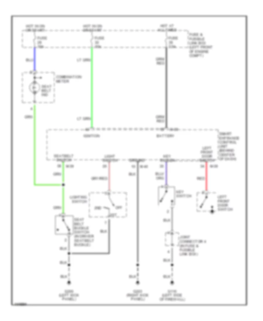
WARNING SYSTEMS Warning System Wiring Diagrams for Nissan Quest GLE 2001 List of elements for Warning System Wiring Diagrams for Nissan Quest GLE 2001: 27 1st 2nd Battery Combination meter Fuse & fusible link box (left front of engine compt) Fuse 10a Fuse 7.5a G116 (left side of firewall) G200 (left kick panel) G203 (right kick panel) Ground Hot at all times Hot in on or start Ignition Joint connector 4 (in fuse & fusible link box) Key switch Left front door switch Light switch Lighting switch M-39 M-40 Off Red Seat belt buckle switch (in driver seatbelt buckle) Seat belt ind Seatbelt switch Smart entrance control unit (behind center of dash)
WIPER/WASHER Front Wiper/Washer Wiring Diagram for Nissan Quest GLE 2001 List of elements for Front Wiper/Washer Wiring Diagram for Nissan Quest GLE 2001: 26 20a Combination switch (wiper switch) E107 Fast Front of engine compt) Front washer motor (in washer reservoir) Front wiper amplifier (left side of firewall) Front wiper motor (left side of firewall) Fuse 8 Fuse block (behind dash, left of steering column) G104 (rear of left front fender) G116 (left side of firewall) High Hot in acc or run J/c-4 (on left Low Move Off Pnk Pnk wiper sw Red Red park Slow Stop Wash Wiper motor Rear Washer/Wiper Wiring Diagram, with Moveable Liftgate Glass for Nissan Quest GLE 2001 List of elements for Rear Washer/Wiper Wiring Diagram, with Moveable Liftgate Glass for Nissan Quest GLE 2001: 23 10a Acc Bat Close Fuse 2 Fuse 9 Fuse block (behind dash, left of steering column) G203 (right kick panel) G402 (left rear wheelwell) Glass hatch latch switch Gnd Hot at all times Hot in acc or run Int wiper Interior light system Latch sw Open Pnk Rear washer motor (in washer fluid reservoir) Rear wiper motor (on center of back door) Rear wiper switch Washer Wiper Rear Washer/Wiper Wiring Diagram, without Moveable Liftgate Glass for Nissan Quest GLE 2001 List of elements for Rear Washer/Wiper Wiring Diagram, without Moveable Liftgate Glass for Nissan Quest GLE 2001: 13 10a Fuse 9 Fuse block (behind dash, left of steering column) G203 (right kick panel) G402 (left rear wheelwell) Hot in acc or run Interior lights system Pnk Rear washer motor (in washer fluid reservoir) Rear wiper motor (on center of back door) Rear wiper switch Washer Wiper