БЛОК ПРЕДОХРАНИТЕЛЕЙ И РЕЛЕ
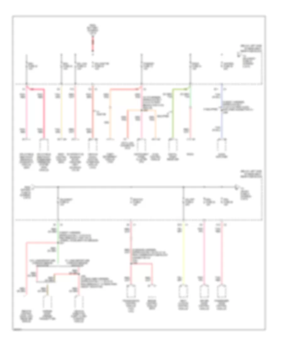
Электросхема блока предохранителей и реле (1 из 5) для Buick Lucerne CXL 2009


Электросхема блока предохранителей и реле (1 из 5) для Buick Lucerne CXL 2009 - Список элементов:
- (in engine harness, approximately 41 cm (16 in) from underhood fuse block connector c3) j111
- (in ip harness, between x201 & x202) j229
- (on right front of engine compt, forward of strut tower) underhood fuse block
- 3.9l
- 4.6l
- A/c clutch relay 34
- Abs fuse 23 50a
- Abs mtr fuse 25 60a
- Air bag fuse 11 10a
- Air pump relay 37
- Air/sol relay 35
- Automatic a/c
- Automatic transmission
- Battery
- Body control module (bcm)
- Ecm/ pcm fuse 9 10a
- Electronic brake control module (ebcm)
- Engine control module (ecm)
- Fan 1 fuse 30a
- Fan 1 relay 33
- Fan 2 fuse 30a
- Fan 2 relay 31
- Fog lamp pcb relay
- From b trn/sig pcb relay (diagram 1 of 5)
- Fusible link
- G112 (lower left rear of engine)
- Generator
- High/beam pcb relay
- Horn pcb relay
- Hvac control module
- Hvac/ipc ign 1 fuse 10 10a
- Ign relay 36
- Inflatable restraint i/p module indicator
- Inflatable restraint sensing & diagnostic module (sdm)
- Instrument panel cluster (ipc)
- J105
- Lo/beam pcb relay
- Manual a/c
- Pnk
- Pnk/red
- Pwr/train relay 29
- Recirculation actuator
- Red
- Starter motor
- Strtr relay 30
- To ecm/ crnk fuse 1 (diagram 5 of 5)
- To rear fuse block (diagram 2 of 5)
- To wpr fuse 13 (diagram 1 of 5)
- Trans ign 1 fuse 8 10a
- Transmission control module (tcm)
- Trn/sig pcb relay
- W/ heated nozzle
- Windshield washer solvent heater
- Wpr fuse 25a
- Wpr hi pcb relay
- Wpr pcb relay
- Wsh pcb relay
- Wsw htr fuse 28 60a
- X175
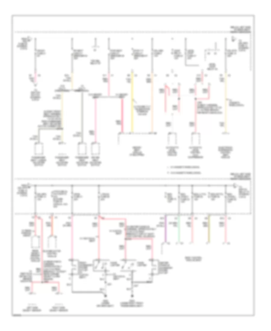
Электросхема блока предохранителей и реле (2 из 5) для Buick Lucerne CXL 2009
Электросхема блока предохранителей и реле (2 из 5) для Buick Lucerne CXL 2009 - Список элементов:
- (below left side of rear seat) rear fuse block
- (in body harness, approximately 10 cm (4 in) from audio amplifier connector c1) j366
- A12
- Amp-rdo fuse 38 30a
- Audio amplifier
- B12
- Bcm fuse 40 10a
- Body control module (bcm)
- Data link connector (dlc)
- Ddm fuse 22 15a
- Digital radio receiver
- Driver door control module
- E11
- Ecm/tcm fuse 5 15a
- Engine control module (ecm)
- Evaporative emission (evap) canister vent solenoid valve
- F10
- From battery (diagram 1 of 5)
- From c amp-rdo fuse 38 (diagram 2 of 5)
- Garage door opener transmitter
- Hvac control module
- If equipped
- Inflatable restraint passenger presence system (pps) module
- Inflatable restraint sensing & diagnostic module (sdm)
- Instrument panel cluster (ipc)
- J392 (in headliner harness, approximately 11 cm (5 in) from breakout to rear park assist indicator)
- Mdl-frt fuse 9 30a
- Mdl-onstar fuse 42 10a
- Mdls-body fuse 43 10a
- Passenger door control module
- Passkey fuse 13 10a
- Pdm fuse 29 15a
- Pnk/ red
- Radio
- Radio fuse 44 15a
- Red
- Remote control door lock receiver (rcdlr)
- Sdm fuse 30 10a
- Seat climate control module
- Sol can fuse 34 10a
- Tan/ red
- Theft deterrent module (tdm)
- To ign-sw fuse 21 (diagram 3 of 5)
- To mdls-body fuse 43 (diagram 2 of 5)
- Transmission control module (tcm) (4.6l)
- Vehicle commu- nication interface module (vcim)
- Vehicle direction alert alarm warning module
- W/ lane departure warning sensor indicator
- W/ onstar
- W/o lane departure warning sensor indicator
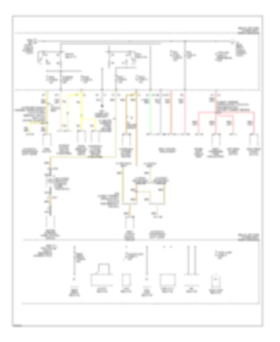
Электросхема блока предохранителей и реле (3 из 5) для Buick Lucerne CXL 2009
Электросхема блока предохранителей и реле (3 из 5) для Buick Lucerne CXL 2009 - Список элементов:
- (below left side of rear seat) rear fuse block
- (in right front seat harness, approximately 114 cm (45 in) from passenger seat adjuster switch connector) j348
- A11
- Apos fuse 31 20a
- Automatic level control (alc) compressor
- Automatic level control module
- Bcm (chmsl) fuse 39 10a
- Bcm (dim) fuse 18 10a
- Bcm (inadv) fuse 32 10a
- Bcm (lttn) fuse 25 15a
- Bcm (rttn) fuse 36 15a
- Blower motor control module
- Body control module (bcm)
- Breakout to right rear corner object alarm sensor) j405
- C10
- Center console accessory power outlet
- Cigar lighter
- Comp relay fuse 24 10a
- Driver seat adjuster switch
- E12
- Electronic suspension control (esc) module
- From d pdm fuse 29 (diagram 2 of 5)
- From e mdl-rtd fuse 15 (diagram 3 of 5)
- Front accessory power outlet (w/ custom seat)
- G300 (under driver's seat)
- G304 (under right front passenger's seat)
- Ign-sw fuse 21 5a
- J221
- J307
- J388 (in body harness, approximately 27 cm (11 in) from branch for rear fuse block)
- Left side object sensor
- Level comp fuse 47 40a
- Level comp relay 53
- Ltr-cig fuse 26 20a
- Mdl-mem fuse 6 10a
- Mdl-rpa fuse 12 10a
- Mdl-rtd fuse 15 25a
- Memory seat module (if equipped)
- Mtr fuse 48 (automatic a/c) blower fuse 49 (manual a/c) 40a
- Passenger seat adjuster switch
- Passenger seat lumbar adjuster switch
- Pwr seat circuit breaker 55 25a
- Pwr t/t circuit breaker 57 25a
- Rear object sensor control module
- Red/ pnk
- Rf seat circuit breaker 54 25a
- Right side object sensor
- To ignition switch (diagram 5 of 5)
- To mdl-rpa fuse 12 (diagram 3 of 5)
- To rap-hc relay 70 (diagram 4 of 5)
- Trk rel relay 67
- W/ custom seat
- W/ individual seat
- W/ magneto rheological
- W/ memory seat
- W/ multi- directional
- W/ obstacle detection sensor indicator
- W/ power tilt telescoping steering column
- W/ rear parking assist
- W/o magneto rheological
- W/o memory seat
- W/o multi- directional
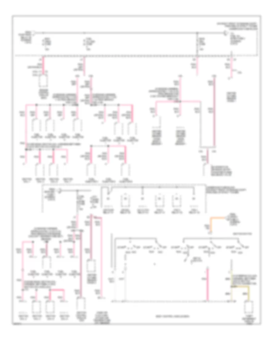
Электросхема блока предохранителей и реле (4 из 5) для Buick Lucerne CXL 2009
Электросхема блока предохранителей и реле (4 из 5) для Buick Lucerne CXL 2009 - Список элементов:
- (below left side of rear seat) rear fuse block
- (chmsl) fuse 39 (diagram 3 of 5)
- (in center console harness, approximately 8 cm (3 in) from breakout for a/t shift lock control solenoid) j381
- A11
- Automatic transmission shift lever
- B11
- Bcm (ctsy) fuse 35 10a
- Bcm fuse 19 10a
- Body control module (bcm)
- Circuit breaker 56 (diagram 4 of 5)
- Driver door module (ddm)
- Drl relay 65
- E11
- From bcm f
- From pwr wdo g
- Front passenger door module (fpdm)
- Fuel pump relay 59
- G301 (under left rear seat)
- Heated steering wheel control module
- Inflatable restraint steering wheel module coil
- Inside rearview mirror (isrvm)
- J302 (in body harness, approximately 19 cm (8 in) from breakout for g301)
- Left rear window switch
- Level comp fuse 47 40a
- Level comp relay 53
- Lock relay 63
- Nca
- Park lp-lt relay 58
- Park switch
- Pwr wdo circuit breaker 56 25a
- Rap-hc relay 70
- Rap1 fuse 28 10a
- Rap2 fuse 33 10a
- Rear defog fuse 46 40a
- Rear defog relay 52
- Right rear window switch
- Run 1 fuse 20 7.5a
- Run 2 fuse 10 10a
- Run relay 64
- Seat climate control module
- Sunroof control module (if equipped)
- Sunroof fuse 17 25a
- Tan
- Tan/ pnk
- To rear defog fuse 46 (diagram 4 of 5)
- Unlock relay 62
- Unlock/lock fuse 14 20a
- W/ custom seat
- W/ front heated seat cooling
- W/ heated nozzle
- W/ heated steering wheel leather wrapped
- W/ individual seat
- W/o front heated seat cooling
- Windshield outside moisture sensor (if equipped)
- Windshield washer solvent heater
- X276
- X277
Электросхема блока предохранителей и реле (5 из 5) для Buick Lucerne CXL 2009
Электросхема блока предохранителей и реле (5 из 5) для Buick Lucerne CXL 2009 - Список элементов:
- (3.9l)
- (4.6l)
- (in engine harness, approximately 3 cm (1 in) from branch for x139) j109
- (in engine harness, approximately 6 cm (2 in) from branch for engine coolant temperature (ect) sensor) j110
- (in engine harness, approximately 7 cm (4 in) from branch for x139 toward breakout for x138) j102
- (in even bank ignition coil harness, between x139 &
- (on right front of engine compt, forward of strut tower) underhood fuse block
- 3.9l
- 4.6l
- A/c cltch relay 34
- Acc
- Air pump relay 37
- Air sol relay 35
- Approximately 3 cm (1 in) from branch for x139) j109
- Body control module (bcm)
- Ecm/ crnk fuse 15a
- Emis dev fuse 15a
- Engine control module (ecm)
- Evaporative emission (evap) canister purge solenoid valve
- Fan 1 relay 33
- Fan 2 relay 31
- Fan 3 relay 32
- From emis dev fuse 7 (diagram 5 of 5)
- From ign-sw fuse 21 (diagram 3 of 5)
- From pwr/train relay 29 (diagram 1 of 5)
- Fuel inj even fuse 15a
- Fuel inj odd fuse 15a
- Fuel injector
- Fuel injector 4
- Fuel injector 5
- Fuel injector 6
- Heated oxygen sensor (ho2s) 1
- Heated oxygen sensor (ho2s) 2
- Heated oxygen sensor (ho2s) bank 1 sensor 1
- Heated oxygen sensor (ho2s) bank 2 sensor 1
- Ignition coil 1
- Ignition coil 2
- Ignition coil 3
- Ignition coil 4
- Ignition coil 5
- Ignition coil 6
- Ignition coil 7
- Ignition coil 8
- Ignition coil/module 8) j131
- Ignition control module (icm)
- Ignition switch
- Key-in switch
- Mass air flow (maf)/ intake aur temperature (iat) sensor
- Off
- Oxy snsr fuse 15a
- Pnk
- Pnk (in odd bank ignition coil harness,between x140 & ignition coil/module 7) j142
- Run
- Start
- Theft deterrent module (tdm)
- To fuel inj even fuse 3 (diagram 5 of 5)
- Underhood fuse block (on right front of engine compt, forward of strut tower)
- X203 & ignition switch connector) j201

 Čeština
 Dansk
Dansk Deutsch
 Ελληνικά
 English
 English
 Español
 Suomi
Suomi Français
 עברית
עברית Hrvatski
 Magyar
 Italiano
 日本語
日本語 한국어
한국어 Nederlands
 Polski
 Português
 Português
 Română
 Русский
 Slovenčina
 Slovenščina
 Svenska
 Türkçe
 中文 (中国)