POWER DISTRIBUTION
Power Distribution Wiring Diagram (1 of 2) for Audi A6 1997


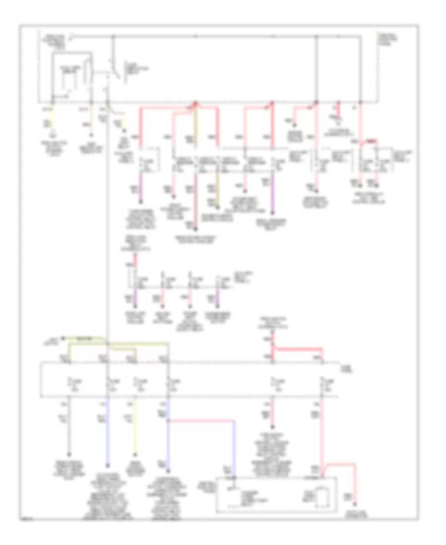
List of elements for Power Distribution Wiring Diagram (1 of 2) for Audi A6 1997:
- (not used)
- 14a
- 15a
- 17a
- 21a
- 50b
- 86s
- 87f
- A/c control head, luggage compartment light, instrument cluster, footwell lights, front interior light, make-up mirror lights, rear fog light switch, memory program switch, selector lever light relay, automatic transmission console light, multifunction transmission range switch, transmission range switch selector lever display, central locking/alarm system/ interior light delay control module, door lock switch, mirror memory control module
- Abs control module, brake light switch
- Acc
- Air bag control module, servotronic control module, shift lock relay, front power window control modules
- Auxiliary relay panel
- Battery
- Battery jump start terminal
- Brake light switch
- Central electric panel
- Central locking/ alarm system/ interior light delay control module
- Cigarette lighter
- Daytime running lights switch-on relay
- Electronic box (right foot- well)
- Engine control module
- Evap canister purge regulator valve, intake manifold change-over valve, egr vacuum regulator solenoid valve, oxygen sensors, secondary air injection pump relay
- Fuel injectors
- Fuel pump
- Fuel pump relay
- Fuse 10a
- Fuse 15a
- Fuse 20a
- Fuse 5a
- Fuse panel
- G202 (behind left side of i/p)
- Generator, instrument cluster
- Headlight dimmer/ flasher switch
- Headlight washer system relay
- Ignition coils, engine control module, mass air flow sensor
- Ignition switch
- Instrument cluster
- Interior lights system
- Key-in ignition switch
- Lamp control module, washer nozzle heaters, malfunction indicator lamp (mil), seat heater switches, central locking/ alarm system/ interior light delay control module, multifunction transmission range switch, heated mirrors, telephone transceiver
- Light switch, drl switch- on relay
- Mirror adjustment switch, instrument cluster, outside air temperature display, mirror control module, memory program switch
- Multi- function transmission range switch
- Off
- Rear fog light switch, fog light switch
- Red
- Run
- S1/50z
- S2/87f
- S3/15
- S3/s
- S4/5
- S4/50z
- S4/a
- S6/50a
- Start
- Starter
- Starter, generator
- Starting interlock relay
- Telephone transceiver
- To fuse 10 (diagram 2 of 2)
- To load reduction relay (diagram 2 of 2)
- Transmission control module
Power Distribution Wiring Diagram (2 of 2) for Audi A6 1997
List of elements for Power Distribution Wiring Diagram (2 of 2) for Audi A6 1997:
- 10a
- 11a
- 12a
- 13a
- 18a
- 19a
- 75a
- 75x
- A/c control head, fresh air recirculation flap two-way valve, a/c refrigerant low pressure switch, engine coolant two- way vacuum valve fresh air blower, interior temperature sensor, a/c clutch relay
- Abs hydraulic unit, abs control module
- Auxiliary relay panel 1
- Auxiliary relay panel 2
- Auxiliary relay panel 3
- Auxiliray relay panel 2
- Central electric panel
- Circuit breaker 20a
- Circuit breaker 30a
- Data link connector
- Door lock control modules
- Dual horn relay
- Engine control module
- Fog light relay
- From fuel pump relay (diagram 1 of 2)
- From ignition switch (diagram 1 of 2)
- From load reduction relay (diagram 2 of 2)
- Front power window control modules
- Fuse 15a
- Fuse 20a
- Fuse 25a
- Fuse 30a
- Fuse 40a
- Fuse 50a
- Fuse panel
- G202 (behind left side of i/p)
- Heated seat switches
- Light switch
- Load reduction relay
- Passenger's power seat switch
- Power sunroof control module
- Rear power window control modules
- Rear window defogger switch
- Rear window wiper/washer relay, rear window washer pump
- Red
- S1/30ah
- S1/31
- S1/75
- Secondary air injection pump relay
- Third speed coolant fan control relay, coolant fan control relay
- To fuse 86 (diagram 2 of 2)
- Turn signal switch, central locking/ alarm system/ interior light delay control module, emergency flasher switch, interior monitoring sensor control module
- Washer/ wiper intermittent relay
- Windshield wiper/washer switch, windshield wiper motor, emergency flasher switch third speed coolant fan control relay, coolant fan control relay

 Čeština
 Dansk
Dansk Deutsch
 Ελληνικά
 English
 English
 Español
 Suomi
Suomi Français
 עברית
עברית Hrvatski
 Magyar
 Italiano
 日本語
日本語 한국어
한국어 Nederlands
 Polski
 Português
 Português
 Română
 Русский
 Slovenčina
 Slovenščina
 Svenska
 Türkçe
 中文 (中国)