TRANSMISSION
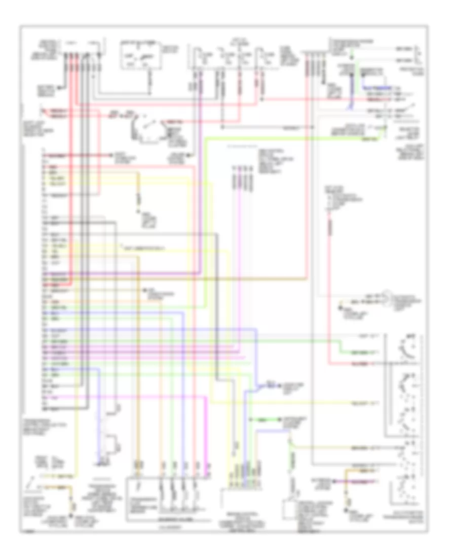
A/T Wiring Diagram for Audi A6 1997
List of elements for A/T Wiring Diagram for Audi A6 1997:
- (below left side of rear seat)
- (not used-fwd only)
- 14a
- 20a
- 28-29
- 3-4
- 44-49
- 51-52
- 87a
- Abs control module (all wheel drive)
- Acc
- Air conditioning system
- Automatic transmission console light
- Automatic transmission fuse 5a
- Auxiliary relay panel 1 (behind left side of dash)
- B11
- Battery positive terminal
- Brake light switch (on pedal cluster)
- C10
- C12
- Central electric panel (behind left side of dash)
- Computer display unit
- Cruise control system
- Data link connector (dlc) (behind console)
- Engine control module (under right footwell carpet, in electronic control box)
- Exterior lights system
- Front all wheel drive
- Fuse 10a
- Fuse 15a
- Fuse 5a
- Fuse panel (behind left side of dash)
- G900 (fwd) (lower left "a" pillar)
- G900 (lower left "a" pillar)
- Generator terminal d+
- Hot at all times
- Hot in on or start
- Ignition switch
- Instrument cluster system
- Interior lights system
- Kick down switch (on throttle valve body, or cable)
- Multi-function transmission range
- Mv1
- Mv2
- Mv3
- Nca
- Off
- Protection diode
- Red
- Red/
- Selector lever light relay
- Shift interlock system
- Shift lock solenoid (front of gear selector)
- Solenoid valves
- Start
- Switch
- T16 central locking/ alarm system/ interior light delay control module (below right side of rear seat)
- Transmission control module (tcm) (behind right kick panel)
- Transmission fluid temperature sensor
- Transmission range (tr) selector lever display
- Transmission vehicle speed sensor (front wheel drive) (left rear of engine compartment)
- Valve body
- Wheel drive
 Čeština
 Dansk
Dansk Deutsch
 Ελληνικά
 English
 English
 Español
 Suomi
Suomi Français
 עברית
עברית Hrvatski
 Magyar
 Italiano
 日本語
日本語 한국어
한국어 Nederlands
 Polski
 Português
 Português
 Română
 Русский
 Slovenčina
 Slovenščina
 Svenska
 Türkçe
 中文 (中国)
 Français