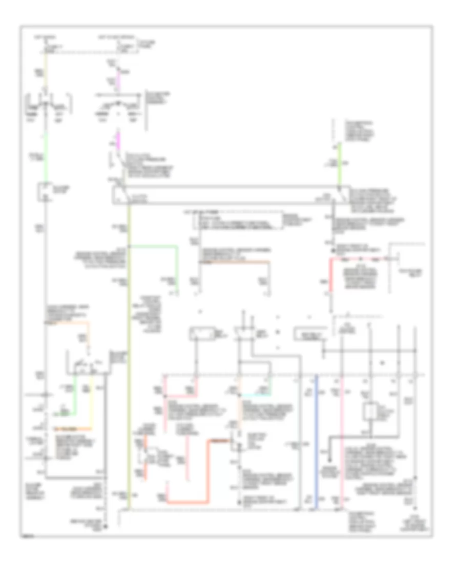
AIR CONDITIONING
3.8L
3.8L, A/C Wiring Diagram for Ford Mustang Cobra 1998
 https://portal-diagnostov.com/license.html
Automotive Electricians Portal FZCO
Automotive Electricians Portal FZCO
https://portal-diagnostov.com/license.html
https://portal-diagnostov.com/license.html
Automotive Electricians Portal FZCO
Automotive Electricians Portal FZCO
List of elements for 3.8L, A/C Wiring Diagram for Ford Mustang Cobra 1998:
- (behind center of dash) g206
- (main harness, near breakout to air bag diagnostic connector) s213
- (not used)
- .5 ohms
- 1.3 ohms
- A/c clutch control
- A/c clutch cycling pressure switch (right rear corner of engine compartment, on a/c accumulator)
- A/c clutch field coil
- A/c high pressure cutout/fan switch (lower right front of engine compartment, on a/c line, right of belt tensioner)
- A/c-heater control assembly
- Blower motor
- Blower motor resistor assembly (behind right side of dash, in a/c-heater plenum)
- Blower motor switch
- Constant control relay module (ccrm) (inside right front fender, behind air filter housing)
- Def
- Edf relay
- Edf relay control
- Electric cooling fan motor
- Engine compartment fuse box
- Fan c.b. 30a
- Floor
- Fuse 17 30a
- Fuse 6 15a
- G100 (left front of engine compartment)
- G101 (right front of engine compartment)
- Hot at all times
- Hot in acc or run
- Hot in run
- I/p fuse panel
- Max
- Mix
- Nca
- Norm
- Off
- Pcm power relay
- Pnk/
- Powertrain control module (pcm) (behind right kick panel)
- S102 (engine control sensor harness, near breakout to octane adjust plug)
- S104 (dash panel to headlamp junction harness, near breakout to g101)
- S115 (engine control sensor harness, near breakout to right front brake sensor)
- S119 (engine control sensor harness, near breakout to a/c high pressure cutout/fan switch)
- S122 (engine control sensor harness, in breakout to electric cooling fan motor)
- S201 (main harness, near breakout to ground g206)
- S226
- Thermal limiter
- Vent
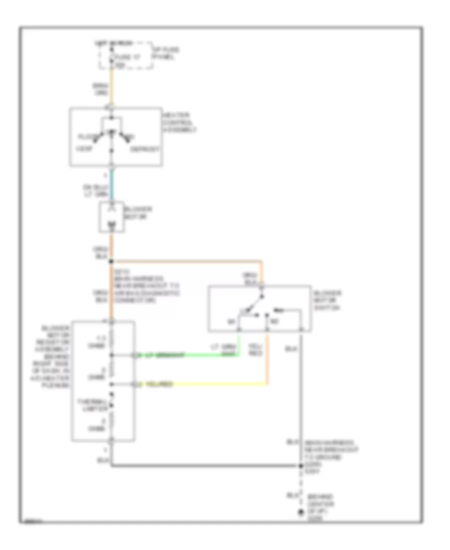
Heater Wiring Diagram for Ford Mustang Cobra 1998
List of elements for Heater Wiring Diagram for Ford Mustang Cobra 1998:
- (behind center of i/p) g206
- .5 ohms
- 1.3 ohms
- Blower motor
- Blower motor resistor assembly (behind right side of dash, in a/c-heater plenum)
- Blower motor switch
- Defrost
- Floor
- Fuse 17 30a
- Heater control assembly
- Hot in run
- I/p fuse panel
- Mix
- Off
- S213 (main harness, near breakout to air bag diagnostic connector)
- Thermal limiter
- Vent
4.6L
4.6L, A/C Wiring Diagram for Ford Mustang Cobra 1998
List of elements for 4.6L, A/C Wiring Diagram for Ford Mustang Cobra 1998:
- (4.6l-2v, engine control harness, near breakout to in-line connector, right rear of engine compartment) (4.6l-4v, engine control harness, in breakout to intake manifold runner control)
- (behind center of dash) g206
- (engine control sensor harness, near breakout to octane adjust plug) s102
- (engine control sensor harness, near breakout to right front brake sensor) s100
- (main harness, near breakout to air bag diagnostic connector) s213
- (right front of engine compartment) g101
- (w/high current fuse panel) (w/o high current fuse panel)
- .5 ohms
- 1.3 ohms
- 30a c.b.
- A/c clutch cycling pressure switch (right rear corner of engine compartment, on a/c accumulator)
- A/c clutch control
- A/c clutch field coil
- A/c high pressure cutout/fan switch (lower right front of engine compartment, on a/c line, above air cleaner housing)
- A/c-heater control assembly
- Blower motor
- Blower motor resistor assembly
- Blower motor resistor assembly (behind right side of dash, in a/c-heater plenum)
- Blower motor switch
- Clutch switch
- Constant control relay module (ccrm) (inside right front fender, behind air filter housing)
- Def
- Edf relay
- Edf relay control
- Electric cooling fan motor
- Engine compartment fuse box
- Engine controls system
- Fan fuse 50a 60a
- Fan switch
- Floor
- Fuse 17 30a
- Fuse 6 15a
- G100 (left front of engine compartment)
- Hedf relay
- High curent fuse panel
- Hot at all times
- Hot in acc or run
- Hot in run
- I/p fuse panel
- Max
- Mix
- Norm
- Off
- Pcm power relay
- Pnk/
- Powertrain control module (pcm) (behind right kick panel)
- Red
- S115 (engine control sensor harness, near breakout to right front brake sensor)
- S116 (engine control sensor harness, near breakout to right front brake sensor)
- S119 (engine control sensor harness, near breakout to a/c high pressure cutout/fan switch)
- S122 (engine control sensor harness, near breakout to a/c high pressure cut/out fan switch)
- S140 (engine control sensor harness, near breakout to a/c high pressure cut/out fan switch)
- S149
- S201 (main harness, near breakout to ground g206)
- S226
- Thermal limiter
- Vent
- W/high current fuse panel
- W/o high current fuse panel
Heater Wiring Diagram for Ford Mustang Cobra 1998
List of elements for Heater Wiring Diagram for Ford Mustang Cobra 1998:
- (behind center of i/p) g206
- .5 ohms
- 1.3 ohms
- Blower motor
- Blower motor resistor assembly (behind right side of dash, in a/c-heater plenum)
- Blower motor switch
- Defrost
- Floor
- Fuse 17 30a
- Heater control assembly
- Hot in run
- I/p fuse panel
- Mix
- Off
- S213 (main harness, near breakout to air bag diagnostic connector)
- Thermal limiter
- Vent

 Čeština
 Dansk
Dansk Deutsch
 Ελληνικά
 English
 English
 Español
 Suomi
Suomi Français
 עברית
עברית Hrvatski
 Magyar
 Italiano
 日本語
日本語 한국어
한국어 Nederlands
 Polski
 Português
 Português
 Română
 Русский
 Slovenčina
 Slovenščina
 Svenska
 Türkçe
 中文 (中国)