TRANSMISSION
4.0L
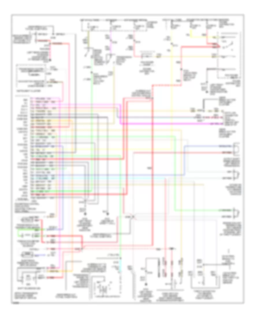
4.0L, 4R55E Transmission Wiring Diagram for Ford Explorer 1996
 https://portal-diagnostov.com/license.html
Automotive Electricians Portal FZCO
Automotive Electricians Portal FZCO
https://portal-diagnostov.com/license.html
https://portal-diagnostov.com/license.html
Automotive Electricians Portal FZCO
Automotive Electricians Portal FZCO
List of elements for 4.0L, 4R55E Transmission Wiring Diagram for Ford Explorer 1996:
- (135 mm from branch to fuel pump relay) s123
- (30 mm from branch to fuel injector 4) s124
- (405 mm from break out to for bmap sensor) s136
- (center of safety wall) g121
- (in break out for powertrain control module) s101
- (in break out to harness in-line connector, rear of engine compartment)
- (left front of engine compartment, near radiator) g100
- (left rear corner of engine compartment, at fender apron) g104
- (left side of automatic transmission) transmission range (tr) sensor
- (near break out for instrument cluster)
- (near break out to fuel injector 6)
- (near break out to fuel injector 6) s166
- (near break out to transmission connector)
- (power for heated oxygen sensors)
- 4r55e transmission (mounted under center of vehicle)
- 87a
- Boo
- Brake on/off (boo) switch (behind steering column)
- C202
- C286
- C288
- Ccs
- Coast clutch solenoid (ccs)
- Cse gnd
- Data link connector (dlc) (partial) (behind left side of instrument panel)
- Dlc
- Dlc (+)
- Dlc (-)
- Ect
- Electronic pressure control (epc) solenoid
- Engine coolant temperature (ect) sensor (mounted front of engine, left of throttle body)
- Epc
- Fuse 10a
- Fuse 13 30a
- Fuse 15a
- Fuse 19 25a
- Fuse 24 15a
- Fuse 4 20a
- Hot at all times
- Hot in run
- Hot in start or run
- Iat
- Instrument cluster
- Intake air temperature (iat) sensor (on intake manifold)
- Interior fuse panel
- Kapwr
- Maf
- Maf rtn
- Malfunction indicator lamp (mil) (check engine)
- Mass air flow (maf) sensor (right rear corner of engine compartment)
- Mil
- N d
- Od off
- Pcm power diode
- Pcm power relay
- Power distribution box
- Powertrain control module (pcm) (mounted through cowl panel)
- Pwr gnd
- Red
- S105
- S113
- S116
- S121
- S125
- S135
- S137
- S146 (100 mm from break out for throttle position sensor)
- S147 (near break out to auxiliary box 3)
- S157
- S162
- S167 (near break out to fuel injector 6)
- S169
- S205
- S206
- Shift solenoid (ss1)
- Shift solenoid (ss2)
- Shift solenoid (ss3)
- Sig rtn
- Ss1
- Ss2
- Ss3
- Tcc
- Tcil
- Tcs
- Tft
- Throttle position (tp) sensor (attached to throttle body)
- Torque converter clutch (tcc) solenoid
- Transmission control indicator lamp (tcil)
- Transmission control switch (tcs)
- Transmission fluid temperature (tft) sensor
- Tss
- Turbine shaft speed (tss) sensor
- Vehicle speed sensor (vss) (attached to transmission)
- Vpwr
- Vref
- Vss
- Vss (-)
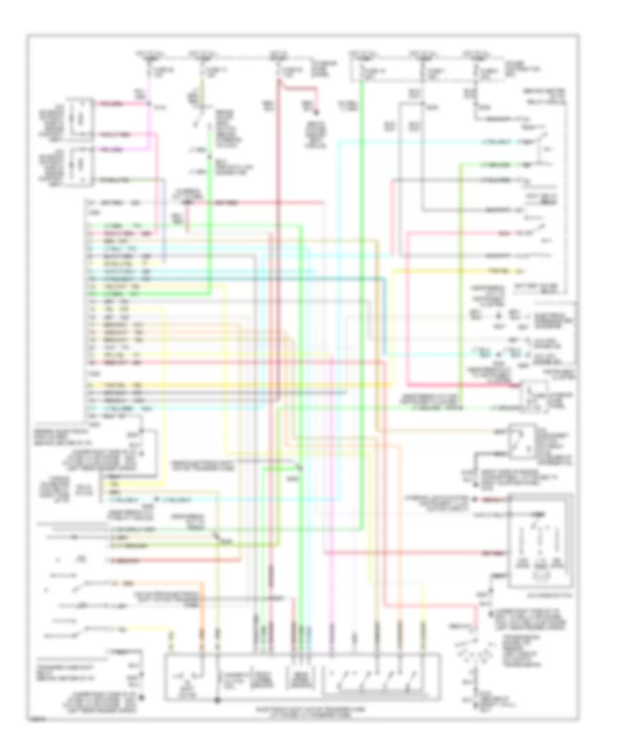
Transfer Case Wiring Diagram for Ford Explorer 1996
List of elements for Transfer Case Wiring Diagram for Ford Explorer 1996:
- (440 mm from electronic shift motor transfer case)
- (behind center of i/p) relay module
- (in break out to gem) s250
- (near break out for instrument cluster) s246
- (near break out to instrument cluster)
- (near break out to radio)
- (near electronic shift motor transfer case)
- (right side of engine compartment, attached to right quarter panel) g105
- (under right side of i/p) g201 g104 (left rear fender apron)
- (w/cellular phone) (w/o cellular phone)
- 1.1k ohms
- 3.9k ohms
- 4x2 solenoid (on right side of engine compart- ment)
- 4x4 disconnect switch (on front axle outboard of differential)
- 4x4 high range ind
- 4x4 low range ind
- 4x4 mode switch
- 4x4 solenoid (on right side of engine compart- ment)
- 87a
- Accy delay relay
- Battery saver relay
- Brake on/off (boo) switch (behind steering column)
- C280
- C282
- C283
- C286
- Electronic shift motor transfer case (attached to transfer case)
- Electronic speedometer/ odometer c287
- Front speed sensor
- Fuse 10a
- Fuse 13 15a
- Fuse 16 20a
- Fuse 26 10a
- Fuse 28 7.5a
- Fuse 5 30a
- Fuse 7 30a
- Generic electronic module (gem) (behind center of i/p)
- H2l
- Hot at all times
- Hot in start
- Instrument cluster
- Interior fuse panel
- Interior lights system (instrument illum- ination circuit)
- L2h
- Magnetic clutch coil
- Mode
- Ohms
- Pnk
- Power distribution box
- Rear speed sensor
- S108 (center of safety wall) g121
- S143
- S159
- S200
- S212 (for data link connector)
- S236
- S238
- S247
- S248
- S249
- S251
- S252
- S259 (near break out to relay module)
- Seats system (memory seat module)
- Shift motor
- Solid state
- Torque on demand (tod) relay (right side of i/p)
- Transfer case shift relay (behind center of i/p)
- Transmission range (tr) sensor (left side of automatic transmission)
5.0L
5.0L, 4R7OW Transmission Wiring Diagram for Ford Explorer 1996
List of elements for 5.0L, 4R7OW Transmission Wiring Diagram for Ford Explorer 1996:
- (100 mm from break out for throttle position sensor)
- (30 mm from branch to fuel injector 4)
- (in break out for powertrain control module) s101
- (in break out to harness in line connector, rear of engine compartment)
- (left front of engine compartment, near radiator) g100
- (left rear corner of engine compartment, at fender apron) g104
- (near break out for instrument cluster)
- (near break out to fuel injector 6)
- (power for heated oxygen sensors)
- 4r70w transmission (mounted under center of vehicle)
- 87a
- Boo
- Brake on/off (boo) switch (behind steering column)
- C202
- C286
- C288
- Case gnd
- Data
- Data link connector (dlc) (partial) (behind left side of i/p)
- Dlc (+)
- Dlc (-)
- Ect
- Electronic pressure control (epc) solenoid
- Engine coolant temperature (ect) sensor (mounted front of engine, left of throttle body)
- Epc
- Fuse 13 15a
- Fuse 13 30a
- Fuse 19 25a
- Fuse 24 20a
- Fuse 26 10a
- Fuse 4 20a
- G100 (left front of engine compartment, near radiator)
- G121 (center of safety wall)
- Hot at all times
- Hot in run
- Hot in start or run
- Iat
- Instrument cluster
- Intake air temperature (iat) sensor (on intake manifold)
- Interior fuse panel
- Kapwr
- Maf
- Maf rtn
- Malfunction indicator lamp (mil) (check engine)
- Mass air flow (maf) sensor (right rear corner of engine compartment)
- Mil
- N d
- Od off
- Oss
- Output shaft speed sensor (left rear of transmission)
- Pcm power diode
- Pcm power relay
- Power distribution box
- Powertrain control module (pcm) (mounted through cowl panel)
- Pwr gnd
- Red
- S105
- S113
- S116
- S123 (135 mm from branch to fuel pump relay)
- S124
- S135
- S137
- S146
- S147 (near break out to auxiliary box 3)
- S157
- S162
- S166
- S167
- S169
- S205
- S206
- Shift solenoids (ss)
- Sig rtn
- Ss1
- Ss2
- Tcc
- Tcil
- Tcs
- Tft
- Throttle position (tp) sensor (attached to throttle body)
- Torque converter clutch (tcc) solenoid
- Transmission control indicator lamp (tcil)
- Transmission control switch (tcs)
- Transmission fluid temperature sensor
- Transmission range (tr) sensor (left side of automatic transmission)
- Vehicle speed sensor (vss) (attached to transmission)
- Vpwr
- Vref
- Vss
Transfer Case Wiring Diagram for Ford Explorer 1996
List of elements for Transfer Case Wiring Diagram for Ford Explorer 1996:
- (440 mm from electronic shift motor transfer case)
- (behind center of i/p) relay module
- (in break out to gem) s250
- (near break out for instrument cluster) s246
- (near break out to instrument cluster)
- (near break out to radio)
- (near electronic shift motor transfer case)
- (right side of engine compartment, attached to right quarter panel) g105
- (under right side of i/p) g201 g104 (left rear fender apron)
- (w/cellular phone) (w/o cellular phone)
- 1.1k ohms
- 3.9k ohms
- 4x2 solenoid (on right side of engine compart- ment)
- 4x4 disconnect switch (on front axle outboard of differential)
- 4x4 high range ind
- 4x4 low range ind
- 4x4 mode switch
- 4x4 solenoid (on right side of engine compart- ment)
- 87a
- Accy delay relay
- Battery saver relay
- Brake on/off (boo) switch (behind steering column)
- C280
- C282
- C283
- C286
- Electronic shift motor transfer case (attached to transfer case)
- Electronic speedometer/ odometer c287
- Front speed sensor
- Fuse 10a
- Fuse 13 15a
- Fuse 16 20a
- Fuse 26 10a
- Fuse 28 7.5a
- Fuse 5 30a
- Fuse 7 30a
- Generic electronic module (gem) (behind center of i/p)
- H2l
- Hot at all times
- Hot in start
- Instrument cluster
- Interior fuse panel
- Interior lights system (instrument illum- ination circuit)
- L2h
- Magnetic clutch coil
- Mode
- Ohms
- Pnk
- Power distribution box
- Rear speed sensor
- S108 (center of safety wall) g121
- S143
- S159
- S200
- S212 (for data link connector)
- S236
- S238
- S247
- S248
- S249
- S251
- S252
- S259 (near break out to relay module)
- Seats system (memory seat module)
- Shift motor
- Solid state
- Torque on demand (tod) relay (right side of i/p)
- Transfer case shift relay (behind center of i/p)
- Transmission range (tr) sensor (left side of automatic transmission)

 Čeština
 Dansk
Dansk Deutsch
 Ελληνικά
 English
 English
 Español
 Suomi
Suomi Français
 עברית
עברית Hrvatski
 Magyar
 Italiano
 日本語
日本語 한국어
한국어 Nederlands
 Polski
 Português
 Português
 Română
 Русский
 Slovenčina
 Slovenščina
 Svenska
 Türkçe
 中文 (中国)