TRANSMISSION
4.0L
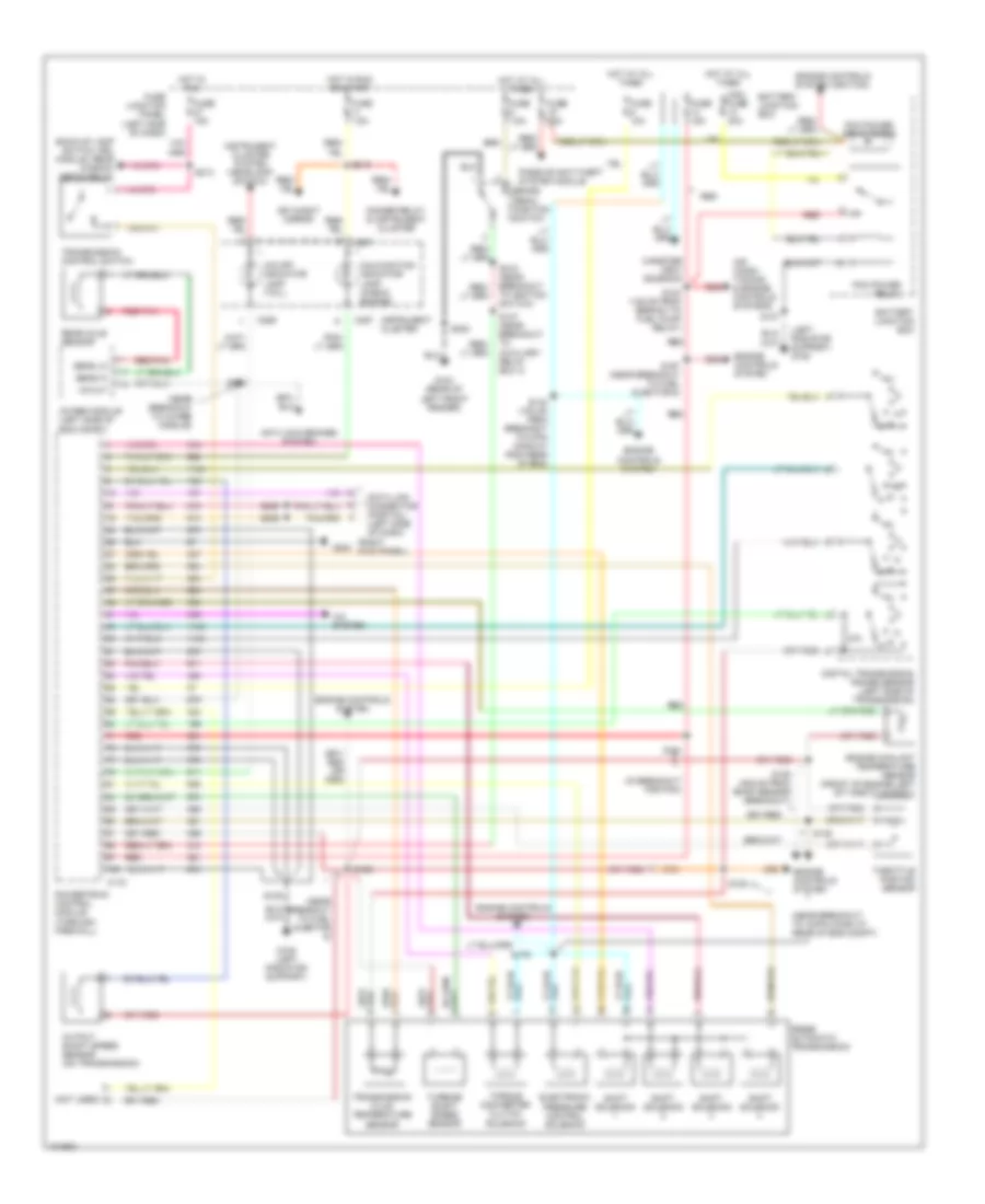
4.0L OHV, Transmission Wiring Diagram, 5R55E for Ford Explorer 1998


List of elements for 4.0L OHV, Transmission Wiring Diagram, 5R55E for Ford Explorer 1998:
- (in breakout for pcm)
- (left radiator support) g108
- (near breakout to 16-pin conn at rear of eng compt)
- (near breakout to 4wabs module)
- (near breakout to fuel injector 6)
- (not used)
- (right kick panel)
- 4wabs module (left side of eng compt)
- 5r55e automatic transmission
- A/c system
- Air condi- tioning & engine controls systems
- Anti-lock brakes system
- Back-up lamp switch, drl module, rear window defog relay
- Battery junction box
- Brake pedal position switch
- C172
- C286
- C287
- Canister vent solenoid
- Data link connector (partial) (left side of dash)
- Day/night mirror
- Digital transmission range sensor (left side of transmission)
- Dimmer relay & instrument cluster
- Electronic pressure control solenoid
- Engine controls system
- Engine controls system (ignition)
- Engine coolant temperature sensor (front of engine left of throttle body)
- Fuse 10a
- Fuse 15a
- Fuse 25a
- Fuse 7.5a
- Fuse junction panel (left side of dash)
- G104 (rear of left front fender)
- G108 (left radiator support)
- G203
- Hot at all times
- Hot in run
- Hot in run or start
- Instrument cluster
- Instrument cluster system (headlamp switch)
- Malfunction indicator lamp (check engine)
- Maxi fuse 30a
- O/d off indicator lamp (tcil)
- Output shaft speed sensor (on transmission)
- Passive anti-theft system module
- Pcm power relay
- Pcm power relay diode
- Powertrain control module (through firewall)
- R p
- Rear axle sensor
- Red
- Red/pnk
- S101
- S105
- S123 (135 mm from branch to fuel pump relay)
- S136 (405 mm from bmap sensor breakout)
- S137
- S142 (100 mm from breakout to 4-pin conn at righ rear of eng)
- S146
- S147 (near breakout to auxiliary relay box 3)
- S166
- S167 (near breakout to fuel injector 6)
- S168
- S179
- S180
- S205
- S206
- S213
- S215 (near breakout to ignition switch)
- S230
- Sens hi
- Sens lo
- Shift solenoid
- Throttle postion sensor
- Torque converter clutch solenoid
- Transmission control switch
- Transmission fluid temperature sensor
- Turbine shaft speed sensor
- Vs out
4.0L SOHC, Transmission Wiring Diagram, 5R55E for Ford Explorer 1998
List of elements for 4.0L SOHC, Transmission Wiring Diagram, 5R55E for Ford Explorer 1998:
- (in breakout for pcm)
- (left radiator support) g108
- (near breakout to 16-pin conn at rear of eng compt)
- (near breakout to 4wabs module)
- (near breakout to fuel injector 6)
- (not used)
- (right kick panel)
- 4wabs module (left side of eng compt)
- 5r55e automatic transmission
- A/c system
- Air condi- tioning & engine controls systems
- Anti-lock brakes system
- Back-up lamp switch, drl module, rear window defog relay
- Battery junction box
- Brake pedal position switch
- C172
- C286
- C287
- Canister vent solenoid
- Data link connector (partial) (left side of dash)
- Day/night mirror
- Digital transmission range sensor (left side of transmission)
- Dimmer relay & instrument cluster
- Electronic pressure control solenoid
- Engine controls system
- Engine controls system (ignition)
- Engine coolant temperature sensor (front of engine left of throttle body)
- Fuse 10a
- Fuse 15a
- Fuse 25a
- Fuse 7.5a
- Fuse junction panel (left side of dash)
- G104 (rear of left front fender)
- G108 (left radiator support)
- G203
- Hot at all times
- Hot in run
- Hot in run or start
- Instrument cluster
- Instrument cluster system (headlamp switch)
- Malfunction indicator lamp (check engine)
- Maxi fuse 30a
- O/d off indicator lamp (tcil)
- Output shaft speed sensor (on transmission)
- Passive anti-theft system module
- Pcm power relay
- Pcm power relay diode
- Powertrain control module (through firewall)
- R p
- Rear axle sensor
- Red
- Red/pnk
- S101
- S105
- S123 (135 mm from branch to fuel pump relay)
- S136 (405 mm from bmap sensor breakout)
- S137
- S142 (100 mm from breakout to 4-pin conn at righ rear of eng)
- S146
- S147 (near breakout to auxiliary relay box 3)
- S166
- S167 (near breakout to fuel injector 6)
- S168
- S179
- S180
- S205
- S206
- S213
- S215 (near breakout to ignition switch)
- S230
- Sens hi
- Sens lo
- Shift solenoid
- Throttle postion sensor
- Torque converter clutch solenoid
- Transmission control switch
- Transmission fluid temperature sensor
- Turbine shaft speed sensor
- Vs out
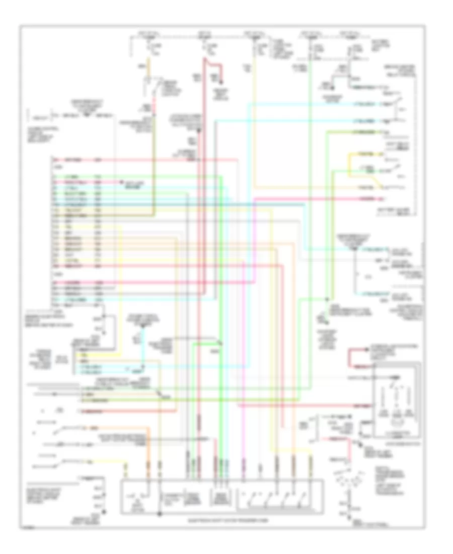
Electronic Transfer Case Wiring Diagram for Ford Explorer 1998
List of elements for Electronic Transfer Case Wiring Diagram for Ford Explorer 1998:
- (440 mm from electronic shift motor transfer case)
- (behind center of dash) relay module
- (in break out to gem) s250
- (left side of automatic transmission)
- (near break out to instrument cluster) s248
- (near break out to relay module)
- (near breakout for instrument cluster)
- (near breakout to instrument cluster) s247
- (near breakout to radio)
- (near electronic transfer case)
- 1.1k ohms
- 3.9k ohms
- 4.0l
- 4wabs control module (left side of eng compt)
- 4wd mode switch
- 4x4 high range ind
- 4x4 low range ind
- 4x4 low range ind c202
- 87a
- A/t
- Accy delay relay
- Anti-lock brakes
- Battery junction box
- Battery saver relay
- Brake pedal position switch
- C280
- C282
- C283
- C286
- Courtesy lamps (interior lights system)
- Digital transmission range sensor (dtr)
- Electronic shift control module (behind center of dash)
- Electronic shift motor transfer case
- Front speed sensor
- Fuse 10a
- Fuse 7.5a
- Fuse junction panel (left side of dash)
- G104 (rear of left front fender)
- G203 (right kick panel)
- Generic electronic module (behind center of dash)
- H2l
- Hot at all times
- Hot in start
- Illumination lamp
- Instrument cluster
- Interior lights system (instrument illumination circuit)
- L2h
- Liftgate wiper/ washer switch, multi-function switch
- M/t
- Magnetic clutch coil
- Maxi fuse 20a
- Maxi fuse 30a
- Memory seat module
- Mode
- Moonroof motor
- Ohms
- Power tops & power windows systems
- Powertrain control module (mounted on firewall)
- Rear speed sensor
- S108
- S200
- S215 (near breakout to ignition switch)
- S236
- S246
- S249
- S251
- S252
- S259
- Shift motor
- Solid state
- Torque on demand relay (right side of dash)
- Vss out
5.0L
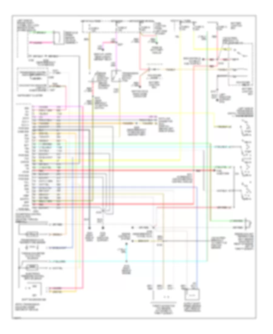
5.0L, Transmission Wiring Diagram, 4R70W for Ford Explorer 1998
List of elements for 5.0L, Transmission Wiring Diagram, 4R70W for Ford Explorer 1998:
- (100 mm from breakout to throttle position sensor)
- (135 mm from breakout to fuel pump relay)
- (left radiator support) g108
- (left side of engine compt) 4 wheel anti-lock brake system (4wabs) module
- (left side of transmission) digital transmission range sensor
- 4r70w transmission (mounted under center of vehicle)
- Back-up lamps, rear window defrost relay
- Battery junction box
- Bpp
- Brake pedal position switch (behind steering column)
- C186
- C202
- C286
- C287
- Case gnd
- Data
- Data link connector (dlc) (partial) (behind left side of dash)
- Dlc (+)
- Dlc (-)
- Ect
- Electronic pressure control (epc) solenoid
- Eng controls, a/c relay, fuel pump rly
- Engine controls system
- Engine coolant temperature (ect) sensor (mounted on front of engine, left of throttle body)
- Epc
- Fuel injectors
- Fuse 10 30a
- Fuse 13 15a
- Fuse 19 25a
- Fuse 27 15a
- Fuse 6 10a
- Fuse 9 7.5a
- Fuse junction panel (left side of dash)
- G108 (left radiator support)
- G203 (right side of dash)
- Hot at all times
- Hot in run
- Hot in start or run
- Ignition coils, radio noise capacitor
- Instrument cluster
- Kapwr
- Malfunction indicator lamp (mil) (check engine)
- Mil
- Od off
- Oss
- Output shaft speed sensor (left rear of transmission)
- Passive anti-theft module
- Pcm power diode
- Pcm power relay
- Powertrain control module (pcm) (mounted through firewall)
- Pwr gnd
- R p
- Rear axle speed sensor (on axle assembly)
- Red
- S101 (in breakout for powertrain control module)
- S105
- S123
- S137
- S142 (right rear of engine)
- S146
- S166 (near breakout to fuel inj 6)
- S168 (near breakout to 4wabs mod)
- S206 (near breakout to ground g201, near battery)
- S207
- S215 (near breakout to ignition switch)
- Shift solenoids (ss)
- Sig rtn
- Ss1
- Ss2
- Tcc
- Tcil
- Tcs
- Tft
- Throttle position (tp) sensor (attached to throttle body)
- Torque converter clutch (tcc) solenoid
- Tr1
- Tr2
- Tr3
- Transmission control indicator lamp (tcil)
- Transmission control switch (tcs)
- Transmission fluid temperature sensor
- Vpwr
- Vref
- Vss
Electronic Transfer Case Wiring Diagram for Ford Explorer 1998
List of elements for Electronic Transfer Case Wiring Diagram for Ford Explorer 1998:
- (440 mm from electronic shift motor transfer case)
- (behind center of dash) relay module
- (in break out to gem) s250
- (left side of automatic transmission)
- (near break out to instrument cluster) s248
- (near break out to relay module)
- (near breakout for instrument cluster)
- (near breakout to instrument cluster) s247
- (near breakout to radio)
- (near electronic transfer case)
- 1.1k ohms
- 3.9k ohms
- 4.0l
- 4wabs control module (left side of eng compt)
- 4wd mode switch
- 4x4 high range ind
- 4x4 low range ind
- 4x4 low range ind c202
- 87a
- A/t
- Accy delay relay
- Anti-lock brakes
- Battery junction box
- Battery saver relay
- Brake pedal position switch
- C280
- C282
- C283
- C286
- Courtesy lamps (interior lights system)
- Digital transmission range sensor (dtr)
- Electronic shift control module (behind center of dash)
- Electronic shift motor transfer case
- Front speed sensor
- Fuse 10a
- Fuse 7.5a
- Fuse junction panel (left side of dash)
- G104 (rear of left front fender)
- G203 (right kick panel)
- Generic electronic module (behind center of dash)
- H2l
- Hot at all times
- Hot in start
- Illumination lamp
- Instrument cluster
- Interior lights system (instrument illumination circuit)
- L2h
- Liftgate wiper/ washer switch, multi-function switch
- M/t
- Magnetic clutch coil
- Maxi fuse 20a
- Maxi fuse 30a
- Memory seat module
- Mode
- Moonroof motor
- Ohms
- Power tops & power windows systems
- Powertrain control module (mounted on firewall)
- Rear speed sensor
- S108
- S200
- S215 (near breakout to ignition switch)
- S236
- S246
- S249
- S251
- S252
- S259
- Shift motor
- Solid state
- Torque on demand relay (right side of dash)
- Vss out

 Čeština
 Dansk
Dansk Deutsch
 Ελληνικά
 English
 English
 Español
 Suomi
Suomi Français
 עברית
עברית Hrvatski
 Magyar
 Italiano
 日本語
日本語 한국어
한국어 Nederlands
 Polski
 Português
 Português
 Română
 Русский
 Slovenčina
 Slovenščina
 Svenska
 Türkçe
 中文 (中国)