HORN
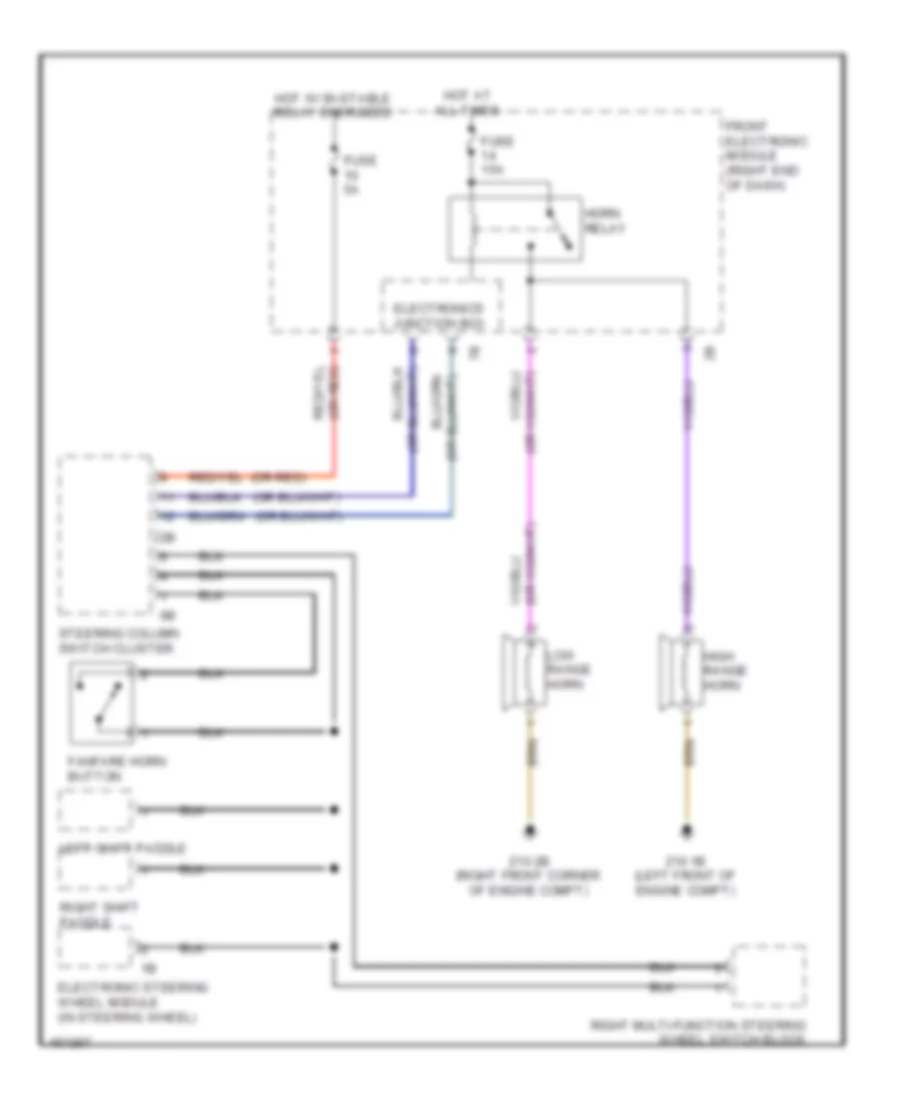
Horn Wiring Diagram for BMW ActiveHybrid 3 2014
List of elements for Horn Wiring Diagram for BMW ActiveHybrid 3 2014:
- (or red)
- Electronic steering wheel module (in steering wheel)
- Electronics junction box
- Fanfare horn button
- Front electronic module (right end of dash)
- Fuse 15a
- Fuse 5a
- High range horn
- Horn relay
- Hot at all times
- Hot w/ bi-stable relay energized
- Left shift paddle
- Low range horn
- Right multi-function steering wheel switch block
- Right shift paddle
- Steering column switch cluster
- Z10 1b (left front of engine compt)
- Z10 2b (right front corner of engine compt)
 Čeština
 Dansk
Dansk Deutsch
 Ελληνικά
 English
 English
 Español
 Suomi
Suomi Français
 עברית
עברית Hrvatski
 Magyar
 Italiano
 日本語
日本語 한국어
한국어 Nederlands
 Polski
 Português
 Português
 Română
 Русский
 Slovenčina
 Slovenščina
 Svenska
 Türkçe
 中文 (中国)
 Français