ENGINE PERFORMANCE
2.0L
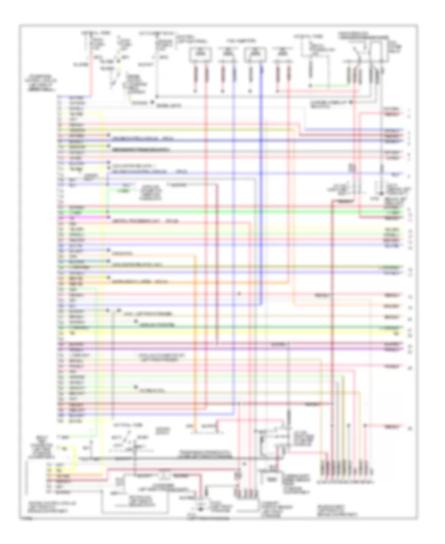
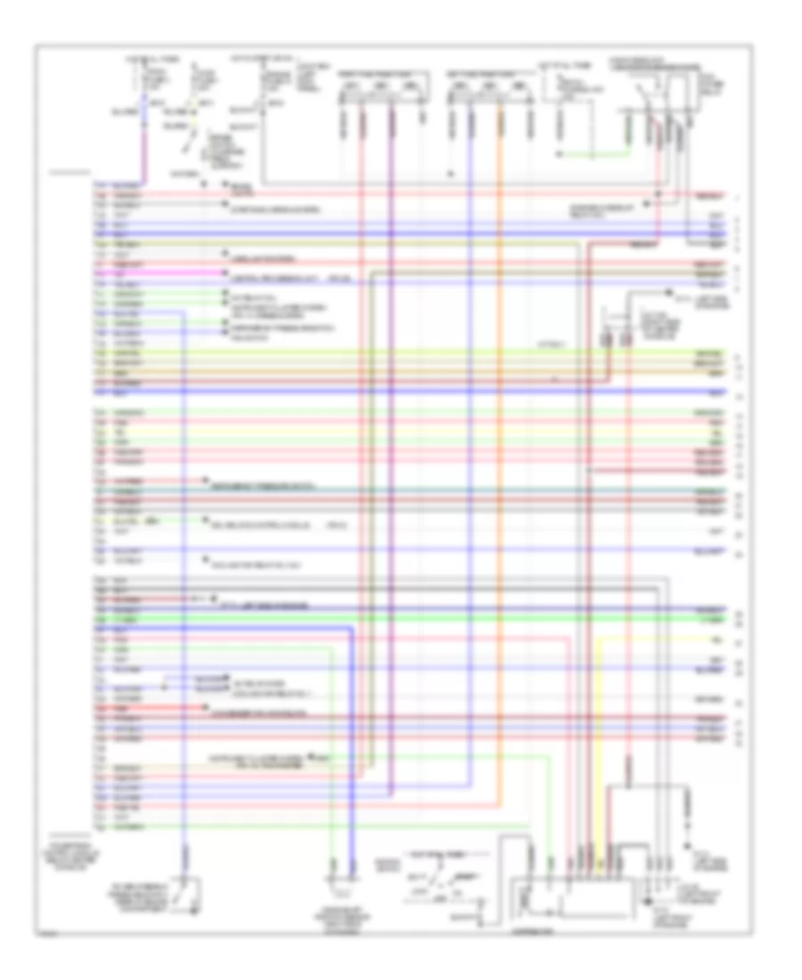
2.0L, Engine Performance Wiring Diagrams, A/T (1 of 2) for Mazda MX-6 1995
List of elements for 2.0L, Engine Performance Wiring Diagrams, A/T (1 of 2) for Mazda MX-6 1995:
- (behind left headlight)
- (left front fender)
- (left front of
- (pin 1n)
- (pin 2s)
- (pin d)
- (pin g)
- A/c relay coil
- Acc
- Brake lights
- Brake switch (on brake pedal support)
- Camshaft position sensor (left front of engine)
- Canada only
- Central processing unit
- Condenser (left side of engine compt)
- Cooling fan relay no. 1
- Cooling fan relay no. 2 & 3
- Cruise control module
- Data link connector (near main fuse block)
- Data link connector (st)
- Drl relay & control module
- Egi inj fusible link 30a
- Engine compartment)
- Engine fuse 10 15a
- Fan switch
- Fuel injectors
- G100
- G106
- G110 (left front of engine)
- Headlights system
- Hot at all times
- Hot in start or on
- Ignition coil (left side of engine compt)
- Ignition control module
- Ignition switch
- Instrument cluster
- J/c x-22 (main fuse box)
- J/c x-22 (right side of center console)
- J/c-01 (behind left headlight)
- J/c-03 (left front of engine)
- Jb-01
- Jb-02
- Jb-03
- Joint box (left kick panel)
- Lock
- Main fuse block (left side of engine compt)
- Off
- Pcm power relay
- Pnk
- Powertrain control module (left side of safety wall)
- Red
- Refrigerant pressure switch refrigerant pressure switch
- Room fuse 2 15a
- Solenoid body (left front of engine compartment)
- Spout test connector (left side of engine compartment)
- Start
- Starter interrupt relay coil
- Stop fuse 1 20a
- Transmission range switch (lower left front of engine)
- Turbine shaft speed sensor (rear of engine compartment)
- Vi0/red
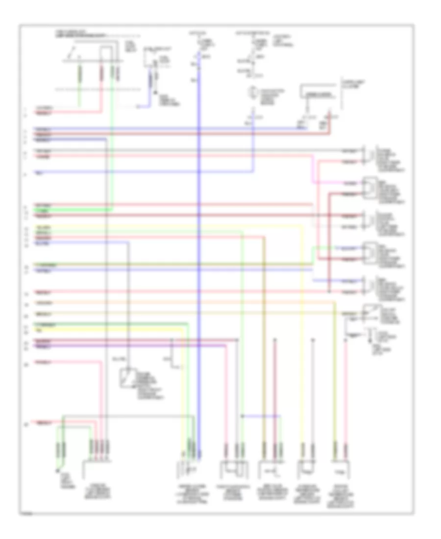
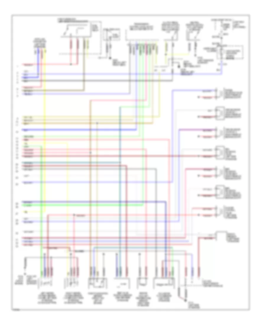
2.0L, Engine Performance Wiring Diagrams, A/T (2 of 2) for Mazda MX-6 1995
List of elements for 2.0L, Engine Performance Wiring Diagrams, A/T (2 of 2) for Mazda MX-6 1995:
- C-01
- C-01 1b
- C-01 1f
- Egr solenoid valve-vacuum (right rear of engine compartment)
- Egr solenoid valve-vent (right rear of engine compartment)
- Egr valve position sensor (center rear of engine compt)
- Engine coolant temperature sensor (left front of engine compt)
- Fuel pump
- Fuel pump relay
- Fuel tank unit
- G100 (left front fender)
- G202 (left side of i/p)
- G409 (rear of cargo bed)
- Heated oxygen sensor (lower right side of engine, on exhaust pipe)
- Hot in on
- Hot in start or on
- Idle air control valve (left rear of engine compartment)
- Instrument cluster
- Intake air temperature sensor (left front of engine compt)
- J/c-02 (left side of i/p)
- Jb-03
- Joint box (left kick panel)
- Main fuse block (left side of engine compt)
- Malfunction indicator (check engine)
- Mass air flow sensor (left rear of engine compt)
- Meter fuse 8 15a
- Nca
- O/d off switch (center console)
- Power steering pressure switch (right front of engine compartment)
- Prc solenoid valve (right rear of engine compartment)
- Purge solenoid valve (right rear of engine compartment)
- Speedometer
- Throttle position sensor (top rear of engine)
- Wiper fuse 13 20a
2.0L, Engine Performance Wiring Diagrams, M/T (1 of 2) for Mazda MX-6 1995
List of elements for 2.0L, Engine Performance Wiring Diagrams, M/T (1 of 2) for Mazda MX-6 1995:
- (left front fender)
- (left side of engine)
- (pin 25)
- (pin d)
- A/c relay coil
- Acc
- Brake lights
- Brake switch (on brake pedal support)
- Canada only
- Central processing unit
- Closed throttle position switch (center rear of engine compartment)
- Cooling fan relay coil
- Data link connector (near main fuse block)
- Distributor
- Drl control module
- Egi inj fusible link 30a
- Engine control module (below center console)
- Engine fuse 10 15a
- Fan switch
- Fuel injectors
- G100
- G100 (left front fender)
- G106 (behind left headlight)
- G112
- G112 (left side of engine)
- Headlights system
- Hot at all times
- Hot in start or on
- Ignition switch
- Instrument cluster system (pin 1g, tachometer)
- Instrument cluster system (pin 1h, speedometer)
- J/c x-05 (right rear of engine)
- J/c x-20 (main fuse box)
- J/c x-21 (main fuse box)
- J/c x-22 (right side of center console)
- J/c-01 (behind left headlight)
- J/c-03 (left front fender)
- Jb-01
- Jb-02
- Jb-03
- Joint box (left kick panel)
- Lock
- Main fuse block (left side of engine compt)
- Off
- Pcm power relay
- Power steering pressure switch (right front of engine compartment)
- Red
- Refrigerant pressure switch
- Room fuse 2 15a
- Start
- Starting system
- Stop fuse 1 20a
2.0L, Engine Performance Wiring Diagrams, M/T (2 of 2) for Mazda MX-6 1995
List of elements for 2.0L, Engine Performance Wiring Diagrams, M/T (2 of 2) for Mazda MX-6 1995:
- C-01
- Clutch pedal switch (on clutch pedal support)
- Cruise control unit (pin j)
- Egr solenoid valve-vacuum (right rear of engine compartment)
- Egr solenoid valve-vent (right rear of engine compartment)
- Egr valve position sensor (center rear of engine compt)
- Engine coolant temperature sensor (left side of engine)
- Fuel pump
- Fuel pump relay
- Fuel tank unit
- G106 (behind left headlight)
- G112 (left side of engine)
- G300 (below left front seat)
- Heated oxygen sensor (lower right side of engine, on exhaust pipe)
- Hot in run
- Hot in start or on
- Idle air control solenoid valve (left rear of engine compartment)
- Instrument cluster
- Intake air temperature sensor (left side of engine)
- J/c x-22 (right side of center console)
- J/c-01 (behind left headlight)
- Jb-03
- Joint box (left kick panel)
- Main fuse block (left side of engine compt)
- Malfunction indicator (check engine)
- Mass air flow sensor (left rear of engine compt)
- Meter fuse 8 15a
- Nca
- Neutral switch (on side of transmission)
- Prc solenoid valve (right rear of engine compartment)
- Purge solenoid valve (right rear of engine compartment)
- Red
- Starter interrupt relay coil
- Throttle position sensor (center rear of engine)
- Wiper fuse 13 20a
2.5L
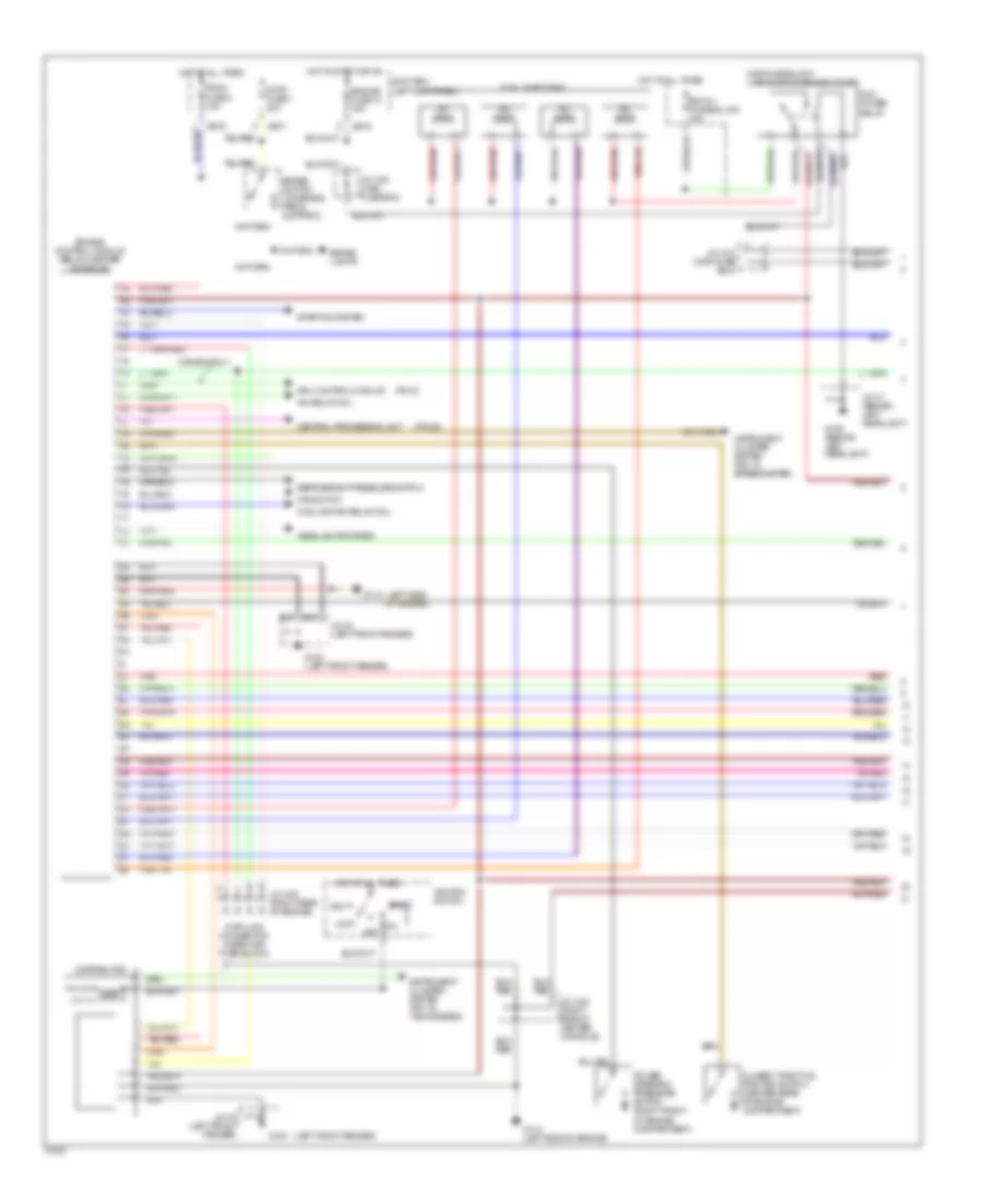
2.5L, Engine Performance Wiring Diagrams (1 of 2) for Mazda MX-6 1995
List of elements for 2.5L, Engine Performance Wiring Diagrams (1 of 2) for Mazda MX-6 1995:
- (left side of engine)
- (pin 2s)
- (pin d)
- A/c relay coil
- A/c relay diode
- Acc
- Brake lights
- Brake switch (on brake pedal support)
- Central processing unit
- Condenser fan high relays
- Cooling fan relay no. 1
- Cooling fan relay no. 2 & 3
- Crankshaft position sensor (right side of engine)
- Distributor
- Drl relay & control module
- Egi inj fusible link 30a
- Engine fuse 10 15a
- Fan switch
- G110 (left front of engine)
- G114
- G114 (left side of engine)
- Headlights system
- Hot at all times
- Hot in start or on
- Ignition switch
- Instrument cluster system (pin 1g, tachometer)
- Instrument cluster system (pin 1h, speedometer)
- J/c x-22 (right side of center console)
- J/c-03 (left front of engine)
- Jb-01
- Jb-02
- Jb-03
- Joint box (left kick panel)
- Left fuel injectors
- Lock
- M/t only
- Main fuse block (left side of engine compt)
- Off
- Pcm power relay
- Pnk
- Power steering pressure switch (rear of engine compartment)
- Powertrain control module (below center console)
- Red
- Refrigerant pressure switch
- Right fuel injectors
- Room fuse 2 15a
- Start
- Starter interrupt relay coil
- Starting/charging system
- Stop fuse 1 20a
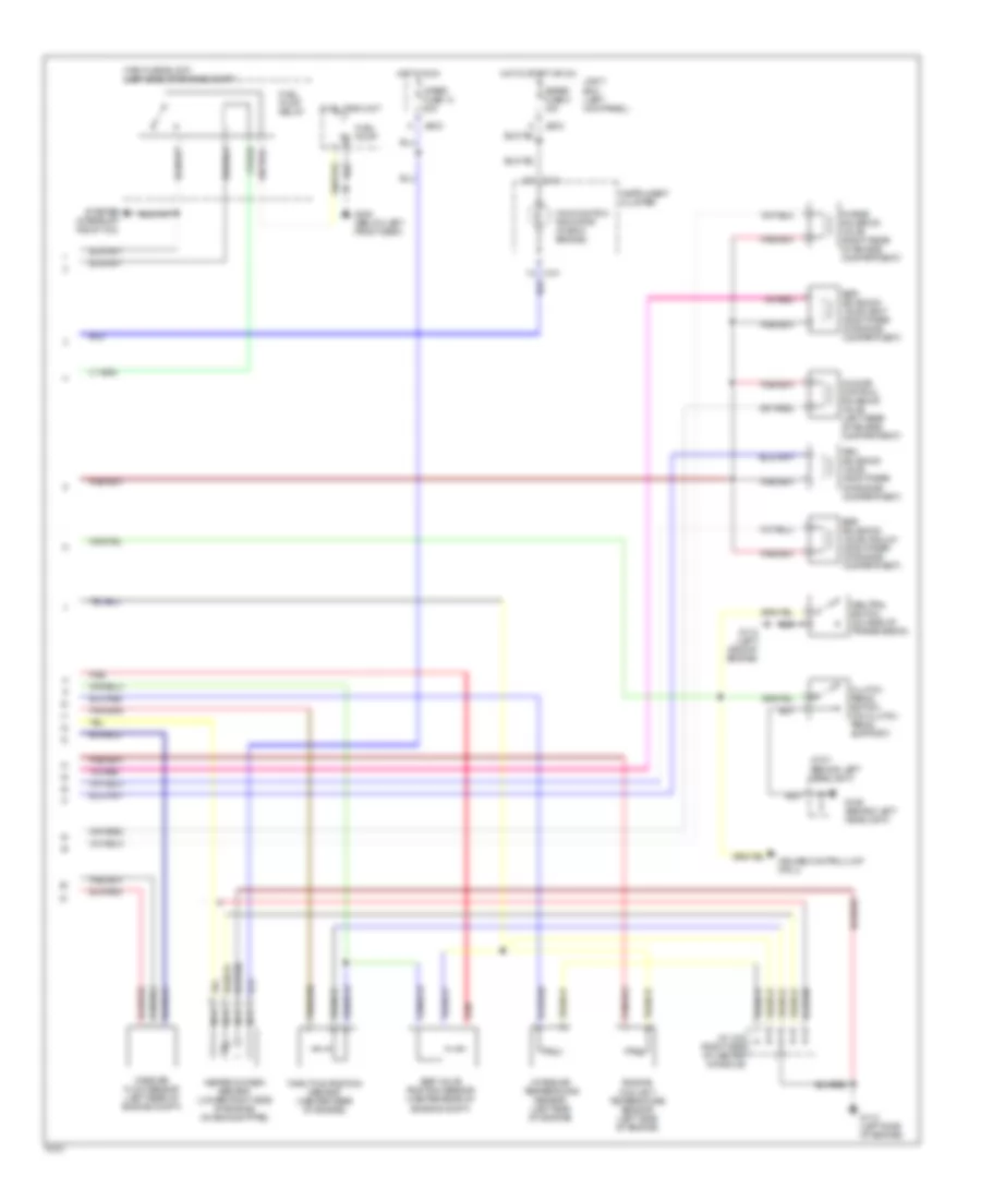
2.5L, Engine Performance Wiring Diagrams (2 of 2) for Mazda MX-6 1995
List of elements for 2.5L, Engine Performance Wiring Diagrams (2 of 2) for Mazda MX-6 1995:
- (a/t)
- A/t
- C-01
- Clutch pedal position switch (m/t) (on clutch pedal support)
- Data link connector (left side of engine)
- Egr solenoid valve-vacuum (right rear of engine compt)
- Egr solenoid valve-vent (right rear of engine compt)
- Egr valve position sensor (center rear of engine)
- Engine coolant temperature sensor (right side of engine)
- Fuel pump
- Fuel pump relay
- Fuel tank unit
- G106 (behind left headlight)
- G108 (left radiator support)
- G114 (left side of engine)
- G134 (m/t) (top of engine)
- G300 (below left front seat)
- Hot in start or on
- Idle air control valve (left side of engine)
- Instrument cluster
- J/c x-22 (right side of center console)
- J/c-01 (behind left headlight)
- Jb-03
- Joint box (left kick panel)
- Knock sensor (left rear of engine)
- Left heated oxygen sensor (lower left side of engine, on exhaust pipe)
- M/t
- Main fuse block (left side of engine compt)
- Malfunction indicator (check engine)
- Meter fuse 8 15a
- Neutral position switch (m/t) (left side of engine)
- Prc solenoid valve (left side of engine)
- Purge solenoid valve (right rear of engine compt)
- Red
- Right heated oxygen sensor (lower right side of engine, on exhaust pipe)
- Throttle position sensor (front top left of engine)
- Transmission control module (a/t) (below center of i/p)
- Volume air flow sensor (left side of engine)
- Vris solenoid valve no. 2 (right rear of engine compt)
- Vris solenoid valve no. 1 (right rear of engine compt)

 Čeština
 Dansk
Dansk Deutsch
 Ελληνικά
 English
 English
 Español
 Suomi
Suomi Français
 עברית
עברית Hrvatski
 Magyar
 Italiano
 日本語
日本語 한국어
한국어 Nederlands
 Polski
 Português
 Português
 Română
 Русский
 Slovenčina
 Slovenščina
 Svenska
 Türkçe
 中文 (中国)