WARNING SYSTEMS
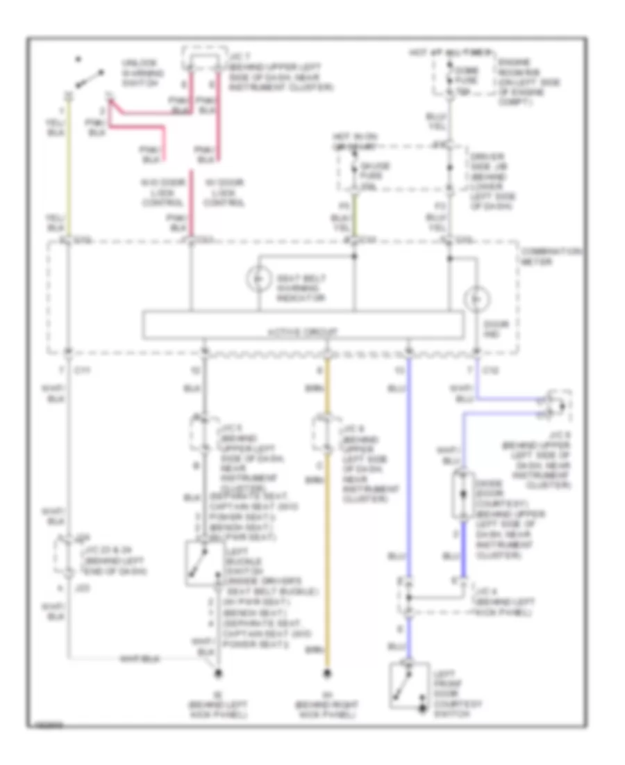
Warning Systems Wiring Diagram, Access/Standard Cab for Toyota Tundra SR5 2004
List of elements for Warning Systems Wiring Diagram, Access/Standard Cab for Toyota Tundra SR5 2004:
- (behind left end of dash)
- (w/ pwr seat)
- (w/ pwr seat) (bench seat) (separate seat, captain seat (w/o power seat))
- Active circuit
- C11
- C12
- C13
- Captain seat (w/o power seat)) (bench seat)
- Combination meter
- Diode (door courtesy) (behind upper left side of dash, near instrument cluster)
- Dome fuse 10a
- Door ind
- Driver side j/b (behind lower left side of dash)
- Engine room r/b (on left side of engine compt)
- Gauge fuse 10a
- Hot at all times
- Hot in on or start
- Ie (behind left kick panel)
- Ih (behind right kick panel)
- J/c 23 & 24
- J/c 4 (behind left kick panel)
- J/c 5 (behind upper left side of dash, near instrument cluster)
- J/c 7 (behind upper left side of dash, near instrument cluster)
- J/c 8 (behind upper left side of dash, near instrument cluster)
- J/c 9 (behind upper left side of dash, near instrument cluster)
- J23
- J24
- Left buckle switch (inside driver's seat belt buckle)
- Left front door courtesy switch
- Seat belt warning indicator
- Unlock warning switch
- W/ door lock control
- W/o door lock control
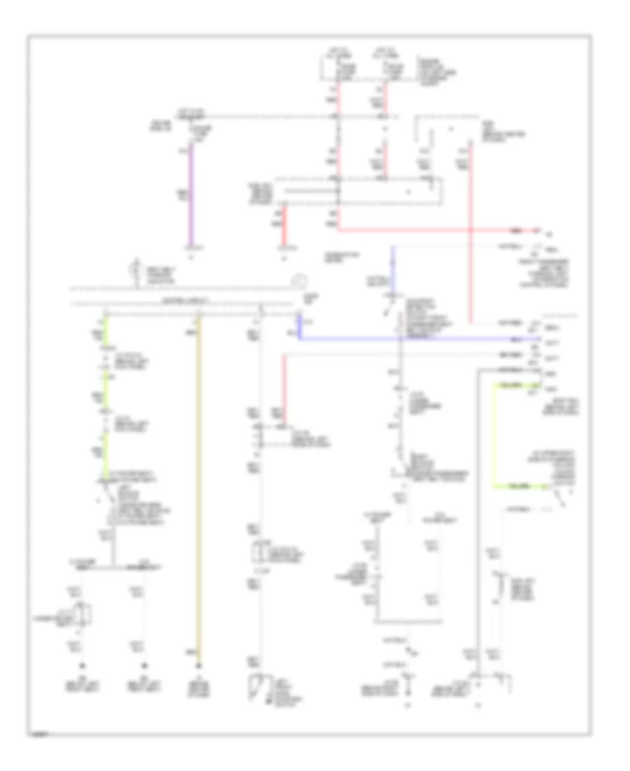
Warning Systems Wiring Diagram, Double Cab for Toyota Tundra SR5 2004
List of elements for Warning Systems Wiring Diagram, Double Cab for Toyota Tundra SR5 2004:
- (in upper right side of steering column) unlock warning switch
- (under driver seat)
- (w/ power seat)
- (w/ power seat) (w/o power seat)
- (w/o power seat)
- A10
- A19
- Acty
- B10
- B11
- Becu
- Body ecu (behind left side of dash)
- Bq (below left front seat)
- C11
- C12
- Combination meter
- Control circuit
- D10
- D12
- Dcty
- Dome fuse 10a
- Door ind
- Driver side j/b
- Ecu-b fuse 7.5a
- Engine room j/b (on left side of engine compt)
- F j42
- Front passenger seat belt warning light (integration control & panel)
- Gauge fuse 15a
- Gnd
- Hot at all times
- Hot in on or start
- I25
- Ip (behind center of dash)
- J/c 17
- J/c 42 & 43 (behind left kick panel)
- J/c 44 (behind left kick panel)
- J/c 45 (behind left side of dash)
- J/c 46 (behind left side of dash)
- J/c 58 (behind right side of dash)
- J/c 61 (under passenger seat)
- J/c 62 (under passenger seat)
- J42 e
- K j43
- Ksw
- L j43
- Left buckle switch (inside driver's seat belt buckle)
- Left front door courtesy switch
- Occupant detection switch (in right front passenger seat belt buckle assembly)
- Pbkl
- Red
- Right buckle switch (inside passenger's seat belt buckle)
- Seat belt warning indicator
- Sub j/b 3 (behind center of dash)
- Sub j/b 4 (behind center of dash)
- W/ power seat
- W/o power seat

 Deutsch
 English
 English
 Español
 Nederlands
 Русский


