Hummer H2 2009 - 2009 GENERAL MOTORS H2
Hummer H2 2009 - BUZZERS, RELAYS & TIMERS
Hummer H2 2009 BUZZERS, RELAYS & TIMERS LOCATION
Component Location A/C CMPRSR Relay Underhood fuse block. See Fig. 94. Air Suspension Relay (1) Mounted on left fender. See Fig. 44. BCK/UP LAMP PCB Relay Underhood fuse block. Not serviceable. See Fig. 38. DEFOG Relay I/P relay block. See Fig. 39. DRL PCB Relay Underhood fuse block. Not serviceable. See Fig. 38. FAN CNTRL PCB Relay Underhood fuse block. Not serviceable. See Fig. 38. FAN CNTRL Relay Under hood fuse block. See Fig. 94. FAN HI PCB Relay Underhood fuse block. Not serviceable. See Fig. 38. FAN HI Relay Under hood fuse block. See Fig. 94. FAN LO PCB Relay Underhood fuse block. Not serviceable. See Fig. 38. FAN LO Relay Under hood fuse block. See Fig. 94. FOG LP Relay Underhood fuse block. See Fig. 38. F/PMP Relay Underhood fuse block. See Fig. 38. FRT WASH PCB Relay Underhood fuse block. Not serviceable. See Fig. 38. HDLP-HI Relay Underhood fuse block. See Fig. 38. HDLP LO/HID Relay Under hood fuse block. See Fig. 94. HDLP-LOW Relay Underhood fuse block. See Fig. 38. HI BEAM PCB Relay Underhood fuse block. Not serviceable. See Fig. 38. HORN PCB Relay Underhood fuse block. Not serviceable. See Fig. 38. HORN Relay Underhood fuse block. See Fig. 38. L/GATE PCB Relay Underhood fuse block. Not serviceable. See Fig. 38. LOCK Relay I/P fuse block. See Fig. 40. LOCK/UNLOCK PCB Relay Underhood fuse block. Not serviceable. See Fig. 38. Park Enable PCB Relay Left I/P Junction Block. PRK LAMP Relay Under hood fuse block. See Fig. 94. PWR/TRN Relay Under hood fuse block. See Fig. 94. REAR DEFOG Relay Under hood fuse block. See Fig. 94. REAR DEFOG Relay Underhood fuse block. See Fig. 38. REAR WASH PCB Relay Underhood fuse block. Not serviceable. See Fig. 38. RR FOG LP Relay I/P fuse block. See Fig. 40. RUN/CRANK Relay Under hood fuse block. See Fig. 94. RUN PCB Relay Underhood fuse block. Not serviceable. See Fig. 38. SPARE Relay I/P relay block. See Fig. 39. STRTR Relay Underhood fuse block. See Fig. 94. TRLR STOP LT PCB Relay Underhood fuse block. Not serviceable. See Fig. 38. TRLR STOP RT PCB Relay Underhood fuse block. Not serviceable. See Fig. 38. UNLOCK Relay I/P fuse block. See Fig. 40. WIPER 1 PCB Relay Underhood fuse block. Not serviceable. See Fig. 38. WIPER 2 PCB Relay Underhood fuse block. Not serviceable. See Fig. 38. W/S WASH Relay Underhood fuse block. See Fig. 38.
Hummer H2 2009 - CIRCUIT PROTECTION DEVICES
Hummer H2 2009 CIRCUIT PROTECTION DEVICES LOCATION
Component Location Body Relay Block Parking brake assembly. See Fig. 19. Fuse Block-Instrument Panel (7) Lower left of I/P. See Fig. 97. Fuse Block-Underhood (3) Left of engine compartment. See Fig. 41. Junction Block-Left I/P (9) Lower left of dash. See Fig. 50. Junction Block-Right I/P (2) Right of dash. See Fig. 50.
Hummer H2 2009 - CONTROL UNITS
Hummer H2 2009 CONTROL UNITS LOCATION
Component Location Air Suspension Control Module (11) Center rear of vehicle. See Fig. 43. Blower Motor Control Module-Auxiliary (3) Rear of auxiliary HVAC module. See Fig. 99. Blower Motor Control Module (7) Right side of dash. See Fig. 46. Body Control Module (BCM) (8) Lower left of dash. See Fig. 50. Electronic Brake Control Module (ECBM) (2) Behind fuse block underhood. See Fig. 41. Engine Control Module (ECM) (5) Left side of engine compartment. See Fig. 41. Fuel Pump Flow Control Module Right rear frame rail. See Fig. 98. Heated Seat Control Module-Rear (3) Under left rear second row seat. See Fig. 57. Inflatable Restraint Sensing & Diagnostic Module (SDM) (7) Left front seat. See Fig. 61. Memory Seat Module Driver seat. See Fig. 33. Powertrain Control Module (PCM) Left front of engine compartment. See Fig. 22. Rear Seat Audio (RSA) Controller Rear of center console. See Fig. 1. Rear Window Wiper/Washer Module Center of liftgate. See Fig. 31. Sunroof Module (10) Front overhead console. See Fig. 48. Theft Deterrent Module (TDM) (5) Ignition key cylinder. See Fig. 60. Transfer Case Shift Control Module Headlight switch. See Fig. 2. Transmission Control Module (TCM) Automatic transmission. Vehicle Communication Interface Module (4) Center of dash. See Fig. 50. Windshield Wiper/Washer Module Windshield cowl. See Fig. 34.
Hummer H2 2009 - MOTORS
Hummer H2 2009 MOTORS LOCATION
Component Location Air Suspension Compressor 1 (9) Center rear of vehicle. See Fig. 43. Air Suspension Compressor 2 (10) Center rear of vehicle. See Fig. 43. Air Temperature Actuator-Auxiliary Front of auxiliary HVAC module. See Fig. 99. Air Temperature Actuator-Left (8) Center of HVAC module assembly. See Fig. 46. Air Temperature Actuator-Right (10) Middle top of HVAC assembly. See Fig. 46. Blower Motor-Auxiliary (4) Rear of auxiliary HVAC module. See Fig. 42. Blower Motor (6) Right lower dash. See Fig. 46. Encoder Motor Rear of transfer case. See Fig. 17. Engine Cooling Fan-Left (5) Left front of engine compartment. See Fig. 47. Engine Cooling Fan-Right (8) Right front of engine compartment. See Fig. 47. Fuel Pump & Sender Assembly (4) In fuel tank. See Fig. 56. Mode Actuator-Auxiliary Auxiliary HVAC assembly. See Fig. 99. Mode Actuator (5) Left side of HVAC assembly. See Fig. 46. Rear Window Wiper Motor Center of liftgate. See Fig. 34. Recirculation Actuator (1) Top front of HVAC assembly. See Fig. 46. Seat Adjuster Motor Assembly-Driver (11) Mounted to driver seat, seat track. See Fig. 67. Seat Adjuster Motor Assembly-Passenger (7) Mounted to passenger seat, seat track. See Fig. 68. Seat Lumbar Horizontal Motor-Driver (5) Driver seat back. See Fig. 67. Seat Lumbar Horizontal Motor-Passenger (9) Passenger seat back. See Fig. 68. Seat Lumbar Vertical Motor-Driver (3) Driver seat back. See Fig. 67. Seat Lumbar Vertical Motor-Passenger (3) In passenger seat back. See Fig. 68. Seat Recline Motor-Driver (1) Driver seat. See Fig. 67. Seat Recline Motor-Passenger (9) Passenger seat. See Fig. 68. Starter Right of engine. See Fig. 37. Transfer Case Encoder Motor Transfer case assembly. See Fig. 18. Window Motor-Driver Driver door. See Fig. 28. Window Motor-Front Passenger Front passenger door. See Fig. 29. Window Motor-LR Left rear door. See Fig. 30. Window Motor Midgate (5) Inside midgate. See Fig. 65. Window Motor-RR Right rear door. See Fig. 36. Windshield Washer Fluid Pump (2) Washer fluid reservoir. See Fig. 47. Windshield Wiper Motor (3) Windshield cowl. See Fig. 47.
Hummer H2 2009 - SENDING UNITS & SENSORS
Hummer H2 2009 SENDING UNITS & SENSORS LOCATION
Component Location Accelerator Pedal Position (APP) Sensor Above accelerator pedal assembly. See Fig. 20. Accelerator Pedal Position (APP) Sensor Connector At APP sensor. See Fig. 20. A/C Refrigerant Pressure Sensor On high pressure line. Air Suspension Pressure Sensor (4) Center rear of vehicle. See Fig. 43. Air Suspension Sensor-Left Rear (6) Left rear frame rail. See Fig. 45. Air Suspension Sensor-Right Rear (3) Right rear frame rail. See Fig. 45. Air Temperature Sensor-Inside (13) Left front headliner. See Fig. 48. Air Temperature Sensor-Lower Left (4) Middle left of dash. See Fig. 46. Air Temperature Sensor-Lower Right (9) Middle right of dash. See Fig. 46. Air Temperature Sensor-Upper Left (3) Top rear of dash. See Fig. 46. Air Temperature Sensor-Upper Right (2) Top rear of dash. See Fig. 46. Ambient Air Temperature Sensor-HVAC (10) Right of radiator support. See Fig. 47. Ambient Light/Sunload Sensor Assembly (5) Top center of dash. See Fig. 49. Automatic Transmission Input & Output Speed Sensor Assembly (2) Inside automatic transmission. See Fig. 51. Battery Current Sensor Negative battery cable assembly. Camshaft Position (CMP) Sensor (8) Front of engine. See Fig. 53. Crankshaft Position (CKP) Sensor Rear of engine block. See Fig. 21. Engine Coolant Temperature (ECT) Sensor (10) Left side engine block. See Fig. 55. Engine Oil Pressure (EOP) Sensor (8) On rear side of engine block. See Fig. 55. Fuel Pressure Sensor Left rear frame rail. See Fig. 98. Fuel Tank Pressure (FTP) Sensor Top of fuel tank. See Fig. 98. Heated Oxygen Sensor (HO2S)-Bank 1 Sensor 1 Left exhaust, before catalytic converter. See Fig. 24. Heated Oxygen Sensor (HO2S)-Bank 1 Sensor 2 Left exhaust, after catalytic converter. See Fig. 24. Heated Oxygen Sensor (HO2S)-Bank 2 Sensor 1 Right exhaust, before catalytic converter. See Fig. 24. Heated Oxygen Sensor (HO2S)-Bank 2 Sensor 2 Right exhaust pipe, after catalytic converter. See Fig. 24. Inflatable Restraint Front End Sensor-Left (6) Bottom of radiator. See Fig. 47. Inflatable Restraint Front End Sensor-Right (7) Bottom of radiator. See Fig. 47. Inflatable Restraint Side Impact Sensor (SIS)-Left Front (15) Inside driver door. See Fig. 63. Inflatable Restraint Side Impact Sensor (SIS)-Left Rear (11) Inside left rear door. See Fig. 64. Inflatable Restraint Side Impact Sensor (SIS)-Right Front (12) Inside passenger door. See Fig. 63. Inflatable Restraint Side Impact Sensor (SIS)-Right Rear (8) Inside right rear door. See Fig. 64. Inflatable Restraint Vehicle Rollover Sensor (5) Below center console. See Fig. 61. Intake Air Temperature (IAT)/Mass Airflow (MAF) Sensor (6) In air induction tube. See Fig. 41. Knock Sensor (KS) 1 (9) Left side of engine. See Fig. 55. Knock Sensor (KS) 2 (14) Right side of engine. See Fig. 53. Knock Sensor Pigtail Top of engine. See Fig. 23. Manifold Absolute Pressure (MAP) Sensor (5) Top rear of engine. See Fig. 53. Seat Lumbar Horizontal Motor Position Sensor-Driver (6) Driver seat back. See Fig. 67. Seat Lumbar Vertical Motor Position Sensor-Driver (2) Driver seat back. See Fig. 67. Seat Recline Motor-Driver Right side of driver seat. Seat Recline Position Sensor-Driver (7) Right side of driver seat back. See Fig. 67. Steering Angle Sensor (2) Mounted to steering column. See Fig. 60. Vehicle Inclination Sensor (SPO Theft) Left dash knee bolster. Vehicle Shock Sensor (SPO Theft) Left of dash. Vehicle Speed Sensor (VSS) Rear of transfer case assembly. See Fig. 26. Wheel Speed Sensor (WSS)-LF (RF Similar) (3) Front wheel hub assembly. See Fig. 44. Wheel Speed Sensor (WSS)-LR (RR Similar) (6) Rear wheel hub assembly. See Fig. 45. Yaw And Lateral Accelerometer Sensor (5) Center console trim panel. See Fig. 61.
Hummer H2 2009 - SOLENOIDS & SOLENOID VALVES
Hummer H2 2009 SOLENOIDS & SOLENOID VALVES LOCATION
Component Location A/C Compressor Clutch (11) Right front of engine. See Fig. 53. Air Suspension Inlet Valve Center rear of vehicle. Automatic Transmission Shift Lock Control Solenoid (6) Transmission shift lever. See Fig. 52. Camshaft Position (CMP) Actuator Solenoid Valve (7) Front of engine. See Fig. 53. Control Solenoid Valve Assembly (1) In automatic transmission. See Fig. 51. Differential Lock Actuator (1) On rear axle differential housing. See Fig. 54. Door Latch Assembly-Driver Inside driver door. See Fig. 28. Door Latch Assembly-LR (RR Similar) Rear of door. See Fig. 30. Door Latch Assembly-Passenger Passenger door. See Fig. 29. Door Lock Actuator-Left Rear Left rear door latch. Door Lock Actuator-Liftgate Center of liftgate. See Fig. 31. Door Lock Actuator-Right Rear Right rear door latch. Evaporative Emission (EVAP) Canister Purge Solenoid (Valve) (2) Left side of intake manifold. See Fig. 55. Evaporative Emission (EVAP) Canister Vent Solenoid Valve (2) Right rear of vehicle. See Fig. 56. Fuel Injector 1 (13) Left side of engine, at cylinder #1. See Fig. 55. Fuel Injector 2 (9) Right side of engine, at cylinder #2. See Fig. 53. Fuel Injector 3 (4) Left side of engine, at cylinder #3. See Fig. 55. Fuel Injector 4 (12) Right side of engine, at cylinder #4. See Fig. 53. Fuel Injector 5 (5) Left side of engine, at cylinder #5. See Fig. 55. Fuel Injector 6 (4) Right side of engine, at cylinder #6. See Fig. 53. Fuel Injector 7 (7) Left side of engine, at cylinder #7. See Fig. 55. Fuel Injector 8 (2) Right side of engine, at cylinder #8. See Fig. 53. Ignition Lock Cylinder Control Solenoid (3) Upper steering column. See Fig. 60. Rear Differential Lock Actuator Top of differential housing. See Fig. 16.
Hummer H2 2009 - SWITCHES
Hummer H2 2009 SWITCHES LOCATION
Component Location A/C Low Pressure Switch (7) Right side of a/c accumulator. See Fig. 41. A/C Refrigerant Pressure Switch Right front of engine. See Fig. 11. Air Suspension Inflator Switch Near right "D" pillar. See Fig. 14. Air Suspension Inflator Switch Connector Right rear frame body mount. See Fig. 9. Automatic Transmission Fluid Pressure (TFP) Manual Valve Position Switch In automatic transmission. See Fig. 26. Automatic Transmission Internal Mode Switch (IMS) (3) Inside automatic transmission. See Fig. 51. Brake Fluid Level Switch (1) Left side of master cylinder. See Fig. 41. Center Console Compartment Lamp Switch (1) Center console storage bin. See Fig. 52. Door Lock Switch-Rear Near right "D" pillar. See Fig. 14. Engine Oil Level Switch Right side of oil pan. See Fig. 22. Hood Ajar Switch Hood latch assembly. Ignition Switch (6) Upper steering column. See Fig. 60. Inflator Air Switch (8) Right "D" pillar. See Fig. 42. Liftgate Ajar Switch-Left Left side of liftgate. See Fig. 31. Liftgate Ajar Switch-Right Lower right side of liftgate. See Fig. 31. Midgate Latch Switch-Left (3) Midgate near left latch assembly. See Fig. 65. Midgate Latch Switch-Right (2) Midgate near right latch assembly. See Fig. 65. Park Brake Switch Connector Parking brake assembly. See Fig. 19. Stop Lamp Switch On top of brake pedal bracket. See Fig. 25. Windshield Washer Fluid Level Switch (1) Windshield washer fluid reservoir. See Fig. 47.
Hummer H2 2009 - MISCELLANEOUS
Hummer H2 2009 MISCELLANEOUS LOCATION
Component Location Accessory Power Outlet-Cargo Right rear of cargo box. Accessory Power Outlet-Rear (7) Mounted in trim panel, below right "D" pillar. See Fig. 42. Audio Amplifier (6) Under front floor console. See Fig. 61. Audio Video Adapter (14) Rear of center console. See Fig. 49. Battery (4) Left of engine compartment. See Fig. 41. Cell Phone/GPS Antenna Left front of roof. See Fig. 27. Cellular & Navigation Antenna Top left front of roof. See Fig. 93. Cellular Telephone Microphone (12) Left front headliner. See Fig. 48. Data Link Connector (DLC) Lower left of dash. See Fig. 5. Data Link Resistor On rear chassis crossmember, near evaporative emission canister. Digital Radio Receiver (1) Behind glove box. See Fig. 50. Electric Locking Differential Case Assembly Rear differential. See Fig. 15. Generator Top of engine. See Fig. 37. Global Positioning System (GPS) Antenna (I/P) On dash. See Fig. 93. Heated Seat Element-Driver Back (1) Under driver seat back. See Fig. 58. Heated Seat Element-Driver Cushion (2) Driver seat cushion. See Fig. 58. Heated Seat Element-Left Rear Cushion (2) Under left rear seat cushion upholstery. See Fig. 57. Heated Seat Element-Passenger Back (1) Under passenger seat back upholstery. See Fig. 59. Heated Seat Element-Passenger Cushion (2) In passenger seat cushion. See Fig. 59. Heated Seat Element-Right Rear Cushion (1) Right rear seat cushion. See Fig. 57. Horn Connector-Left At horn. See Fig. 32. Horn-Left (4) Left radiator core support. See Fig. 47. Horn-Right (11) Right radiator core support. See Fig. 47. Ignition Coil (1) Left side of engine. See Fig. 55. Ignition Coil 2 (10) Right side of engine. See Fig. 53. Ignition Coil 3 (12) Left side of engine. See Fig. 55. Ignition Coil 4 (13) Right side of engine. See Fig. 53. Ignition Coil 5 (3) Left side of engine. See Fig. 55. Ignition Coil 6 (3) At right side of engine. See Fig. 53. Ignition Coil 7 (6) Left side of engine. See Fig. 55. Ignition Coil 8 (1) Right side of engine. See Fig. 53. Inflatable Restraint I/P Module (9) Right of dash. See Fig. 49. Inflatable Restraint Roof Rail Module-Left Front (3) Behind rear of left "C" pillar. See Fig. 61. Inflatable Restraint Roof Rail Module-Left Rear (9) Above left quarter window. See Fig. 42. Inflatable Restraint Roof Rail Module-Right Front (2) Rear of right "C" pillar. See Fig. 62. Inflatable Restraint Roof Rail Module-Right Rear (5) Above right quarter window. See Fig. 42. Inflatable Restraint Steering Wheel Module Coil (1) On steering column. See Fig. 60. Inflatable Restraint Steering Wheel Module (4) Under horn pad. See Fig. 49. Infrared Transmitter (3) In roof-mounted DVD system. See Fig. 91. JP410 Inside right rear cargo area, middle of right rear "D" pillar. See Fig. 10. Junction Block-Battery Cable Part of positive battery cable assembly. JX205 (2) Below left side of dash, to left of steering column. See Fig. 73. JX206 (8) Below left side of dash, near instrument panel to engine compartment pass through. See Fig. 73. JX207 (2) Left side of dash, near left kick panel. See Fig. 77. Locking Differential Coil Assembly Rear differential. See Fig. 15. Midgate Latch-Left (4) Inside left side of midgate. See Fig. 65. Midgate Latch-Right (1) Inside right side of midgate. See Fig. 65. Parking Brake Assembly Left side of dash. See Fig. 19. Radio Antenna Right front of vehicle. See Fig. 93. Rearview Camera (10) Center of rear bumper. See Fig. 66. Remote Control Door Lock Receiver (RCDLR) (5) Center of dash. See Fig. 50. Seat Belt Pretensioner-Driver (1) Driver seat belt retractor assembly. See Fig. 61. Seat Belt Pretensioner-Passenger (3) Passenger seat belt retractor assembly. See Fig. 62. SIR Coil Top of steering column. See Fig. 12. Theft Deterrent Control Module Electric Park Lock In steering column. See Fig. 13. Throttle Body Assembly (6) Mounted to intake manifold. See Fig. 53. Trailer Connector (11) Rear of vehicle. See Fig. 66. Video Display (4) Headliner. See Fig. 91. Windshield Washer Solvent Heater Left rear engine compartment.
Hummer H2 2009 - CONNECTORS
Hummer H2 2009 CONNECTORS LOCATION
Component Location X100 (24 Pin) (7) Below underhood fuse block. See Fig. 70. X103 (Black, 16 Pin) (2) Underhood fuse block. See Fig. 69. X104 (Black, 24 Pin) (6) Underhood fuse block. See Fig. 70. X110 (Black, 8 Pin) (2) Left rear engine compartment. See Fig. 70. X111 (Black, 6 Pin) (8) Left engine compartment. See Fig. 70. X120 (Black, 5 Pin) (2) Left front engine. See Fig. 71. X148 (Light Gray, 7 Pin) (6) In engine harness to left ignition coil harness. See Fig. 72. X158 (Light Gray, 7 Pin) (4) In engine harness to right ignition coil harness. See Fig. 72. X200 (Black, 16 Pin) (5) Left dash kick panel. See Fig. 73. X201 (Gray, 22 Pin) (4) Below steering column. See Fig. 73. X204 (Black, 40 Pin) (1) Behind left side of dash. See Fig. 73. X205 (Black, 18 Pin) (3) Left side of dash. See Fig. 73. X207 (Yellow, 4 Pin) (4) Left kick panel. See Fig. 77. X208 (Black, 16 Pin) (7) Left kick panel. See Fig. 73. X209 (Black, 2 Pin) Security indicator jumper harness. X235 (COAX) Instrument panel harness. See Fig. 96. X245 (Black, 8 Pin) Steering column. X246 (Light Green, 2 Pin) Steering column. X247 (Light Green, 2 Pin) Steering column. X248 (Black, 4 Pin) Steering column. X290 (Black, 18 Pin) (3) Passenger kick panel. See Fig. 74. X295 (Black, 4 Pin) (5) Passenger kick panel. See Fig. 74. X296 (Yellow, 2 Pin) (4) Passenger kick panel. See Fig. 74. X298 (Black, 16 Pin) (1) Right kick panel. See Fig. 74. X300 (Black, 8 Pin) (4) Left side of midgate. See Fig. 76. X303 (Black, 30 Pin) (7) Under driver seat. See Fig. 77. X304 (Black, 16 Pin) (2) In overhead console. See Fig. 78. X305 (Black, 30 Pin) (8) Under passenger seat. See Fig. 79. X307 (Black, 8 Pin) (1) Below right rear seat. See Fig. 80. X308 (Black, 8 Pin) (4) Below left rear seat. See Fig. 81. X315 (Black, 8 Pin) (4) Under vehicle, near left side frame rail. See Fig. 82. X320 (Black, 8 Pin) (6) In center console, below automatic transmission shift lever. See Fig. 77. X324 (Black, 18 Pin) (4) In back of driver seat. See Fig. 67. X325 (Black, 6 Pin) (2) In back of passenger seat. See Fig. 68. X334 (Black, 2 Pin) (4) In center console, below automatic transmission shift lever. See Fig. 52. X350 (Black, 40 Pin) (6) In center console, below automatic transmission shift lever. See Fig. 74. X400 (Black, 8 Pin) (3) Below right rear corner of vehicle. See Fig. 75. X401 (Black, 2 Pin) (9) Right rear of vehicle, behind bumper. See Fig. 82. X402 (Black, 2 Pin) (2) Below right rear corner of vehicle. See Fig. 75. X406 (Black, 4 Pin) (2) At rear roof line, above liftgate opening. See Fig. 83. X408 (12 Pin) (2) Right rear of cargo area, behind passenger side trim panel. See Fig. 80. X411 (Black, 8 Pin) (1) Below vehicle, in left rear corner near frame. See Fig. 82. X412 (Black, 8 Pin) (10) Below vehicle, in right rear corner near frame. See Fig. 82. X450 (Black, 2 Pin) (12) At rear underside of vehicle, near air suspension compressor assembly. See Fig. 43. X451 (Black, 24 Pin) (1) At rear underside of vehicle, near front of air suspension compressor assembly. See Fig. 43. X500 (Black, 8 Pin) (2) Driver side kick panel. See Fig. 84. X600 (Black, 4 Pin) (5) In passenger side kick panel. See Fig. 79. X700 (Black, 17 Pin) (9) Left side "B" pillar. See Fig. 77. X800 (Black, 17 Pin) (3) At right side "B" pillar. See Fig. 85. X900 (Gray, 12 Pin) At rear roof line, above liftgate opening. See Fig. 35. X901 (Black, 12 Pin) Liftgate harness to liftgate jumper harness.
Hummer H2 2009 - GROUNDS
Hummer H2 2009 GROUNDS LOCATION
Component Location Fuel Tank Filler Ground Left rear frame body mount. See Fig. 8. G100 (5) On left front frame body mount. See Fig. 69. G101 (6) Right front corner of vehicle on frame rail near front tow hook. See Fig. 69. G102 (3) Left front side of engine block. See Fig. 71. G103 (4) On front of right cylinder head. See Fig. 71. G104 (5) At rear of left cylinder head. See Fig. 72. G106 On rear of engine compartment, near left cylinder head. See Fig. 3. G200 On left side of dash, behind left kick panel. See Fig. 4. G203 Lower right side of dash, behind right kick panel. G300 On left side body mount, in front of driver door. See Fig. 92. G301 (9) Under passenger seat, near X305. See Fig. 79. G302 In left "B" pillar behind trim panel. See Fig. 6. G304 (8) On right side middle body mount, near second row seating area. See Fig. 82. G306 In right "B" pillar, behind trim panel. See Fig. 7. G401 Left rear frame body mount. See Fig. 8. G402 Attached to front of air suspension mounting bracket. G403 (3) Left rear of passenger compartment, near midgate behind trim panel. See Fig. 81. G405 (11) At right rear frame body mount. See Fig. 82. G410 (3) On passenger side rear of body, near "D" pillar behind trim panel. See Fig. 80.
Hummer H2 2009 - SPLICES
Hummer H2 2009 SPLICES LOCATION
Component Location J100 (4) Forward lamp harness, 28 cm from junction of left horn harness. See Fig. 69. J101 (7) Forward lamp harness, 5 cm from ambient temperature sensor harness. See Fig. 69. J102 (1) Engine harness, 4 cm from knock sensor connector harness. See Fig. 72. J103 (3) Engine harness, 10 cm from junction of fuel injector No. 3 harness to engine harness. See Fig. 72. J107 (8) Forward lamp harness, 5 cm from breakout to left horn. See Fig. 69. J108 (3) In forward lamp harness, 10 cm from breakout to right horn. See Fig. 69. J110 (2) Chassis harness, 8 cm from fuse block underhood X3 breakout. See Fig. 86. J127 Speed sensor jumper internal to transmission. J130 (2) Engine harness, 16 cm from engine control module breakout. See Fig. 72. J140 Ignition coil jumper harness, between ignition coils 5 & 7, 3 cm from ignition coil 5 breakout. J141 Ignition coil jumper harness, between ignition coils 5 & 7, 3 cm from ignition coil 5 breakout. J142 Ignition coil jumper harness, 5 cm from X111 breakout, between breakouts for ignition coils 3 & 5. J160 Ignition coil jumper harness, between ignition coils 4 & 2, 3 cm from ignition coil 4 breakout. J161 Ignition coil jumper harness, between ignition coils 4 & 2, 3 cm from ignition coil 4 breakout. J162 Ignition coil jumper harness, 5 cm from X111 breakout, between breakouts for ignition coils 4 & 6. J201 Infotainment harness in X350 breakout, 6 cm from main harness. J203 (3) I/P harness, in I/P fuse block, X1 breakout, 29 cm from fuse block I/P X1. See Fig. 89. J204 (12) I/P harness, in I/P fuse block, X1 breakout, 24 cm from fuse block, I/P X1. See Fig. 89. J212 In steering column harness, between X201 & ignition switch. See Fig. 90. J213 In steering column harness, between ignition switch & body control module. See Fig. 90. J214 (14) I/P harness, 5 cm from driver information center breakout. See Fig. 89. J215 (1) I/P harness, 6 cm from HVAC control module breakout. See Fig. 89. J217 (4) I/P harness, 25.4 cm down from headlight panel dimmer switch. See Fig. 89. J218 In steering column harness. J219 In steering column harness. J220 (8) I/P harness, 5 cm from X205 breakout. See Fig. 89. J221 (9) I/P harness, 10 cm from X205 breakout. See Fig. 89. J225 (6) I/P harness, 7.5 cm from window switch, global breakout. See Fig. 89. J227 In SPO theft accessory harness. J228 In SPO theft accessory harness. J229 In SPO theft accessory harness. J230 (7) I/P harness in body control module breakout, 5 cm from JX205 breakout. See Fig. 89. J231 (2) I/P harness, 5 cm from transfer case control module breakout. See Fig. 89. J232 (15) I/P harness, 14 cm from breakout to X298. See Fig. 89. J233 (16) I/P harness, 9 cm from breakout to X298. See Fig. 89. J234 (13) I/P harness, in transfer case control module breakout, 7 cm from breakout. See Fig. 89. J235 In steering wheel harness between right & left steering wheel control switches. J236 Dash harness. J238 Heated steering wheel module harness. J278 (5) I/P harness in window switch, global breakout, 10 cm from breakout. See Fig. 89. J296 In steering column harness. J300 (5) Headliner harness, at top of left "A" pillar, near corner of windshield. See Fig. 78. J301 (4) Headliner harness, at top of left "A" pillar, near corner of windshield. See Fig. 78. J303 In roof marker harness, 22 cm from right front marker lamp connector. See Fig. 27. J309 Driver seat harness. J310 (12) In body harness, 14 cm from G301 breakout. See Fig. 87. J311 Drivers seat harness, 5 cm from adjuster motor breakout. J312 In driver seat harness. J313 Driver seat harness. J316 Passenger seat harness. J320 (7) In body harness, 8.5 cm from right "B" pillar courtesy lamp harness junction to body harness. See Fig. 87. J321 In overhead console harness. J332 (5) In body harness, 12 cm from marker lamp, rear breakout. See Fig. 87. J333 (4) In body harness, 15 cm from marker lamp, left rear breakout. See Fig. 87. J334 (5) In midgate harness, 10 cm from midgate latch, right breakout. See Fig. 76. J335 (7) In midgate harness, 13 cm from midgate latch, left breakout. See Fig. 76. J336 (1) In midgate harness, 13 cm from left midgate latch breakout. See Fig. 76. J337 (6) In midgate harness, 40 cm from midgate latch, right breakout. See Fig. 76. J338 (2) In midgate harness, 5 cm from midgate latch, left breakout. See Fig. 76. J339 (3) In midgate harness, 5 cm from midgate latch release switch, right breakout. See Fig. 76. J340 (9) In body harness, 10 cm from driver's seat belt pretensioner breakout. See Fig. 87. J341 (10) In body harness, 5 cm from inflatable restraint sensing & diagnostic module breakout. See Fig. 87. J345 In roof marker harness, 16.5 cm from junction of right center roof lamp connector to roof marker harness. See Fig. 27. J351 (2) In console harness, 28.5 cm from junction of body harness in line X320 to floor console harness. See Fig. 88. J352 (3) In console harness, 16 cm from console bin lamp breakout. See Fig. 88. J355 (1) In chassis harness, 5 cm from electronic brake control module X2 breakout. See Fig. 86. J356 (3) In chassis harness, 20 cm from air suspension relay main harness breakout. See Fig. 86. J358 (10) In chassis harness, 10 cm from G300 breakout. See Fig. 86. J360 (9) In chassis harness, 10 cm from fuel pump flow control module main harness breakout. See Fig. 86. J375 In chassis harness, 63.5 cm from rear differential lock actuator, on chassis harness. J376 In chassis harness, 63.5 cm down from rear differential lock actuator, on chassis harness. J380 In passenger seat harness, 21 cm from seat adjuster switch, between lumbar bolster switch & seat adjuster switch, on right side of seat. J381 In passenger seat harness, 16 cm from lumbar bolster switch between seat adjuster switch & lumbar switch on right side of seat. J382 Driver seat harness, 20 cm from body harness. J390 Left side near "B" pillar, 18.5 cm from junction of SIR module & driver seat harness to body harness. J393 Right rear seat harness, 34 cm from heated seat module towards inline connector X380. J400 Chassis harness, at right rear frame rail, 15 cm from junction of right rear air suspension sensor to chassis harness. J401 In chassis harness, at right rear frame rail, 30 cm from junction of right rear air suspension harness to chassis harness. J402 In chassis harness, 33 cm from G405 breakout. J403 (7) In chassis harness, 39 cm from G401 breakout. See Fig. 86. J404 (8) In chassis harness, 15 cm from G401 breakout. See Fig. 86. J405 (6) In chassis harness, 13 cm from G405 main harness breakout. See Fig. 86. J406 (4) In chassis harness, 19 cm from rear differential lock actuator breakout. See Fig. 86. J407 (5) In air chassis harness, 23 cm from data link resistor breakout. See Fig. 86. J408 In air suspension harness at rear underside of vehicle. J409 In air suspension harness at rear underside of vehicle. J410 (1) In body harness, 10 cm from X900 breakout. See Fig. 87. J411 (SUV) (8) Body harness, 15.2 cm from junction of left rear marker lamp to body harness. See Fig. 87. J414 In air suspension harness, at rear underside of vehicle. J415 Air suspension harness, 12 cm from rear chassis harness. J416 Air suspension harness, 12 cm from rear chassis harness. J417 Air suspension harness, 15 cm from air suspension control module. J418 Air suspension harness, 15 cm from air suspension control module. J441 Rear HVAC harness. J442 Rear HVAC harness. J443 Rear HVAC harness. J600 Passenger door harness, 12 cm from window motor takeout. See Fig. 95. J720 In right rear door harness, 12 cm from junction of speaker connector harness to door harness. J820 11.5 cm from junction of door courtesy lamp connector harness to door harness. J900 Left side of liftgate, near junction of right rear defogger connector to liftgate harness. See Fig. 31. J901 Lower right side of liftgate, 10 cm from junction of rear wiper motor connector to liftgate harness. See Fig. 31. J902 Lower right side of liftgate, 6.5 cm from right liftgate ajar switch junction to liftgate harness. See Fig. 31. 411 (SUT) Body harness near right rear marker lamp harness junction.
Hummer H2 2009 - COMPONENT LOCATION GRAPHICS
NOTE:
Fig.res may show multiple component locations. - appropriate table for proper figure references.

Fig. 1: Hummer H2 2009 - Component Locations - Front Floor Console
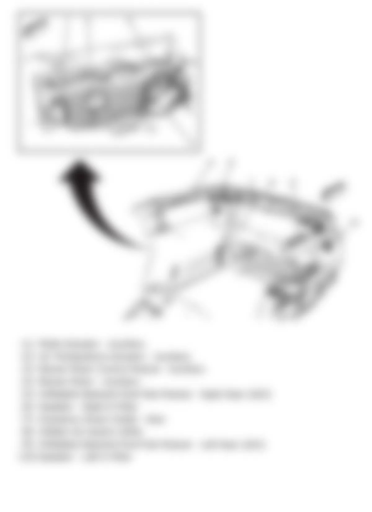
Fig. 2: Hummer H2 2009 - Component Locations - Left Side Of Dash
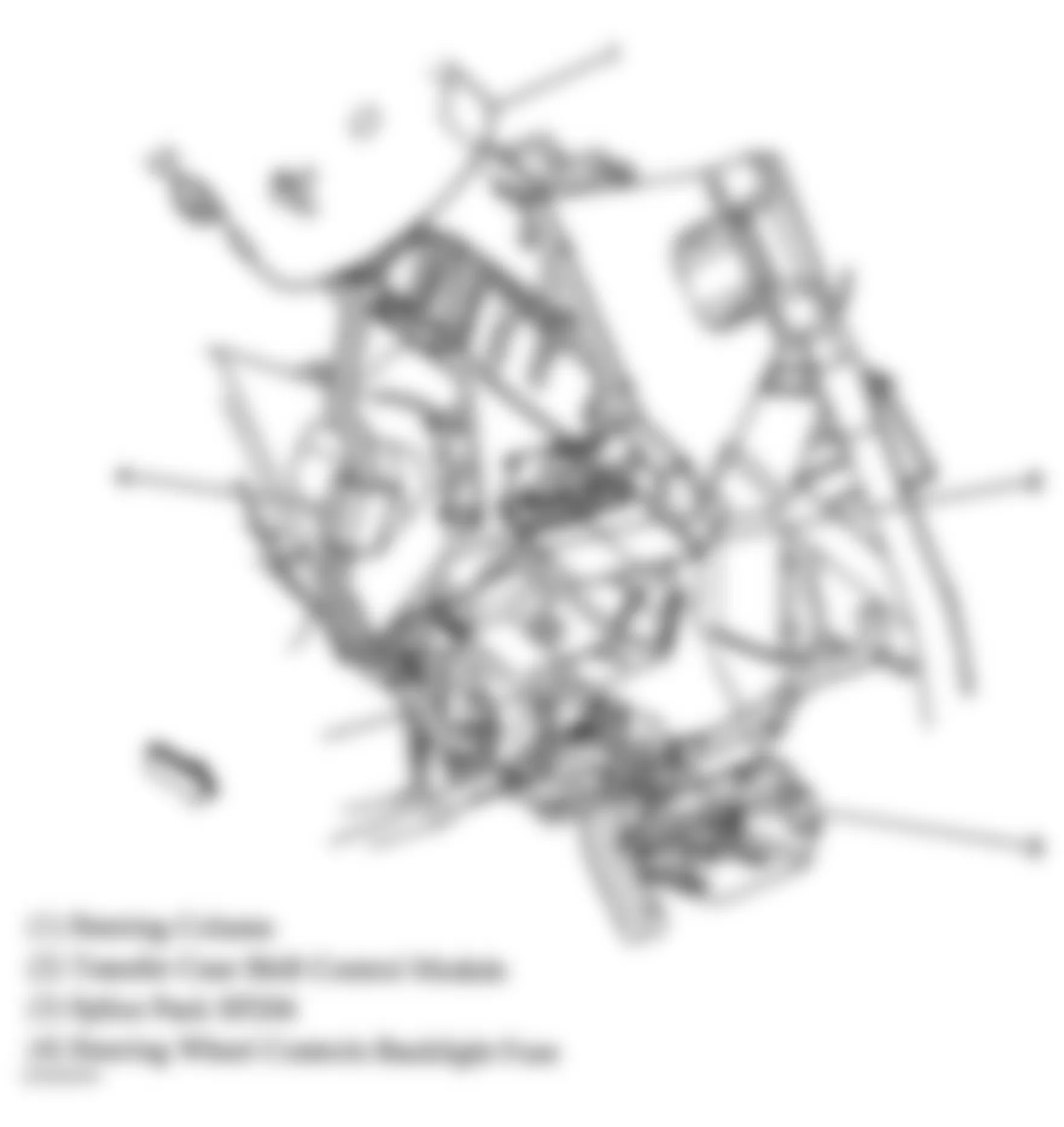
Fig. 3: Hummer H2 2009 - Component Locations - Rear Of Engine Compartment
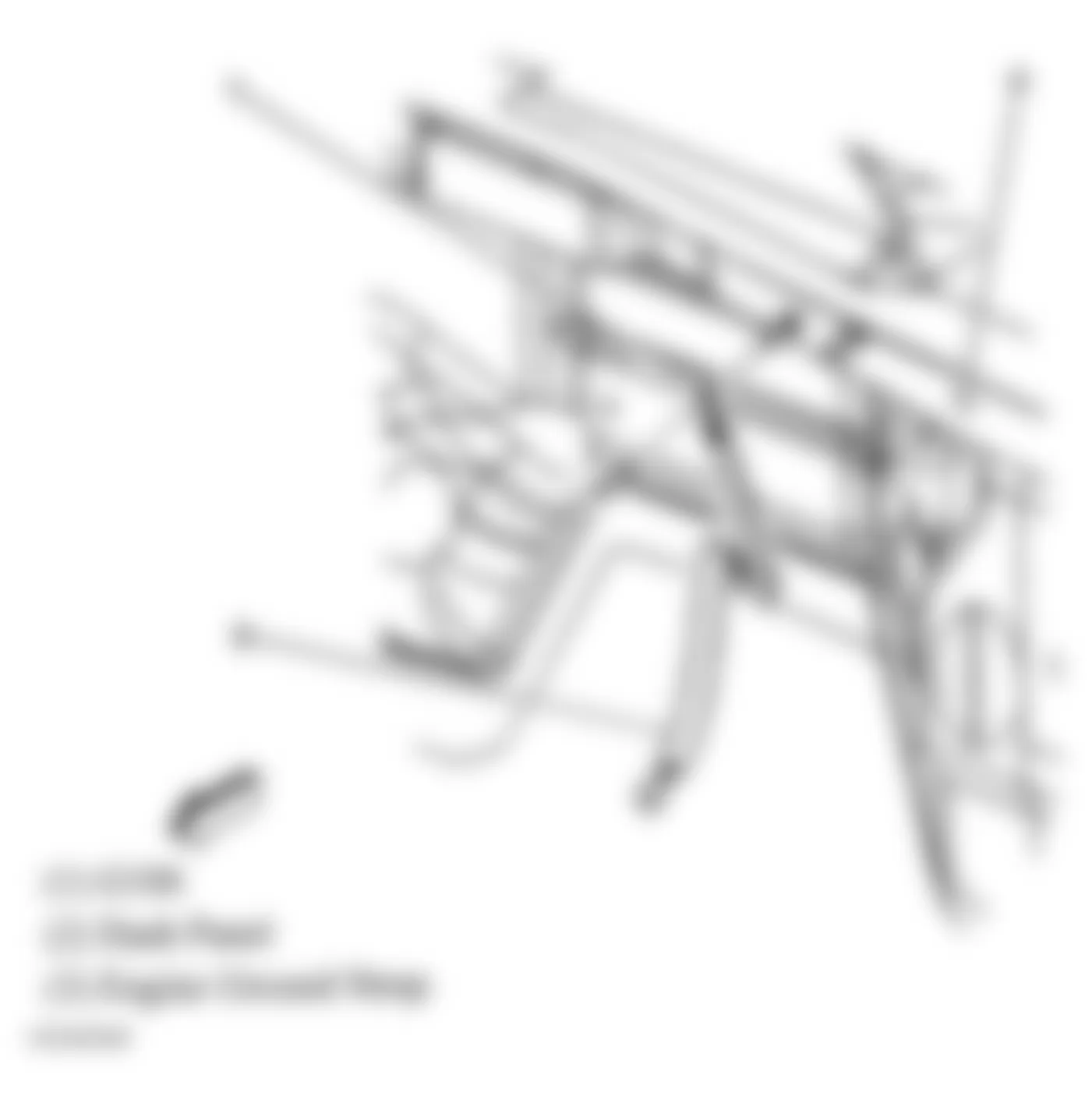
Fig. 4: Hummer H2 2009 - Component Locations - Left Kick Panel
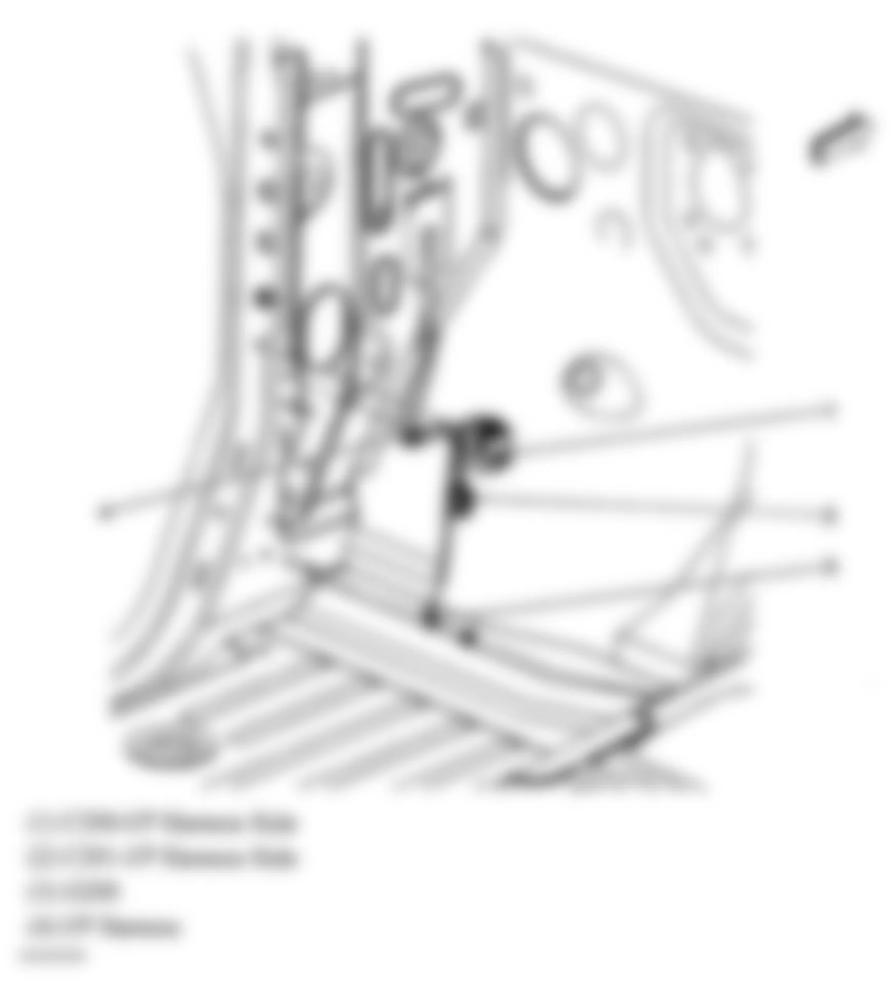
Fig. 5: Hummer H2 2009 - Component Locations - Left Side Of Dash
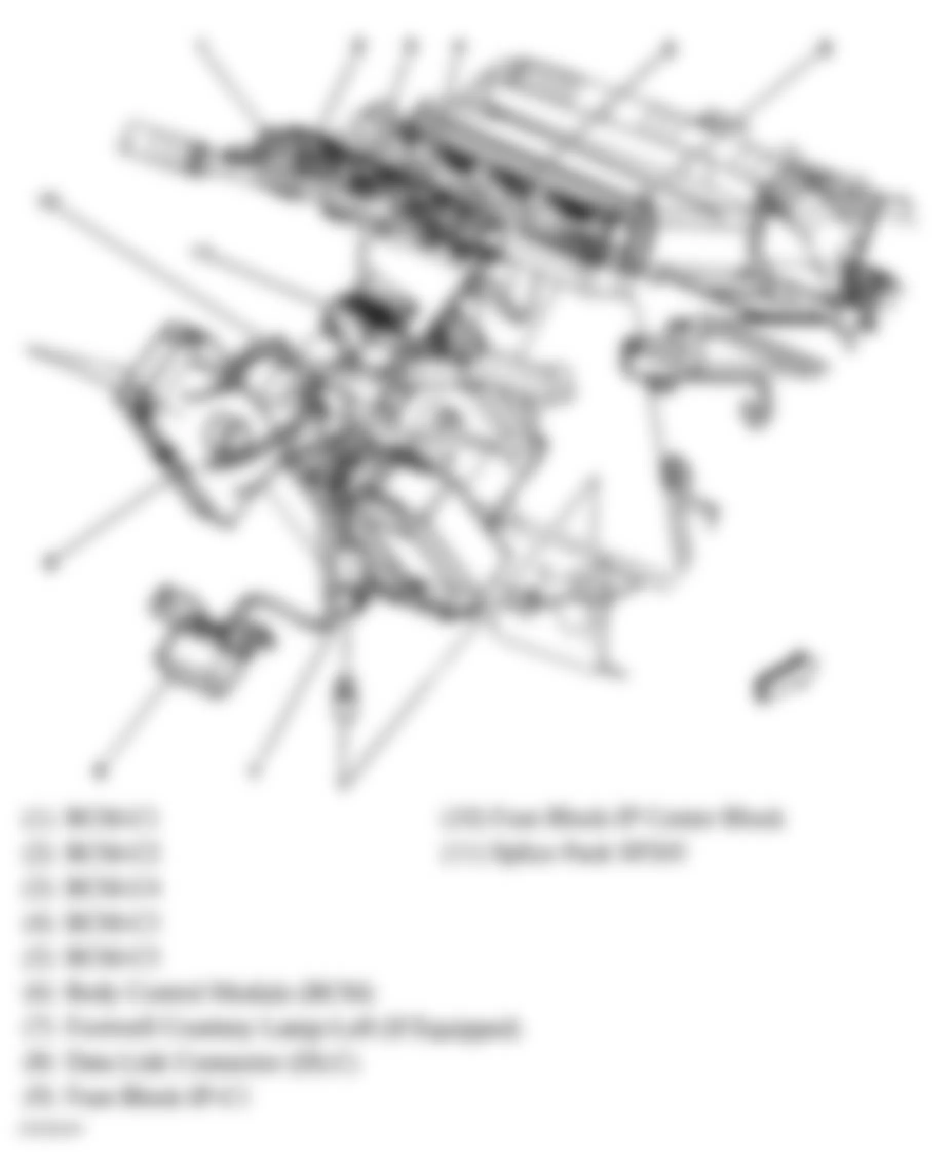
Fig. 6: Hummer H2 2009 - Component Locations - Left "B" Pillar
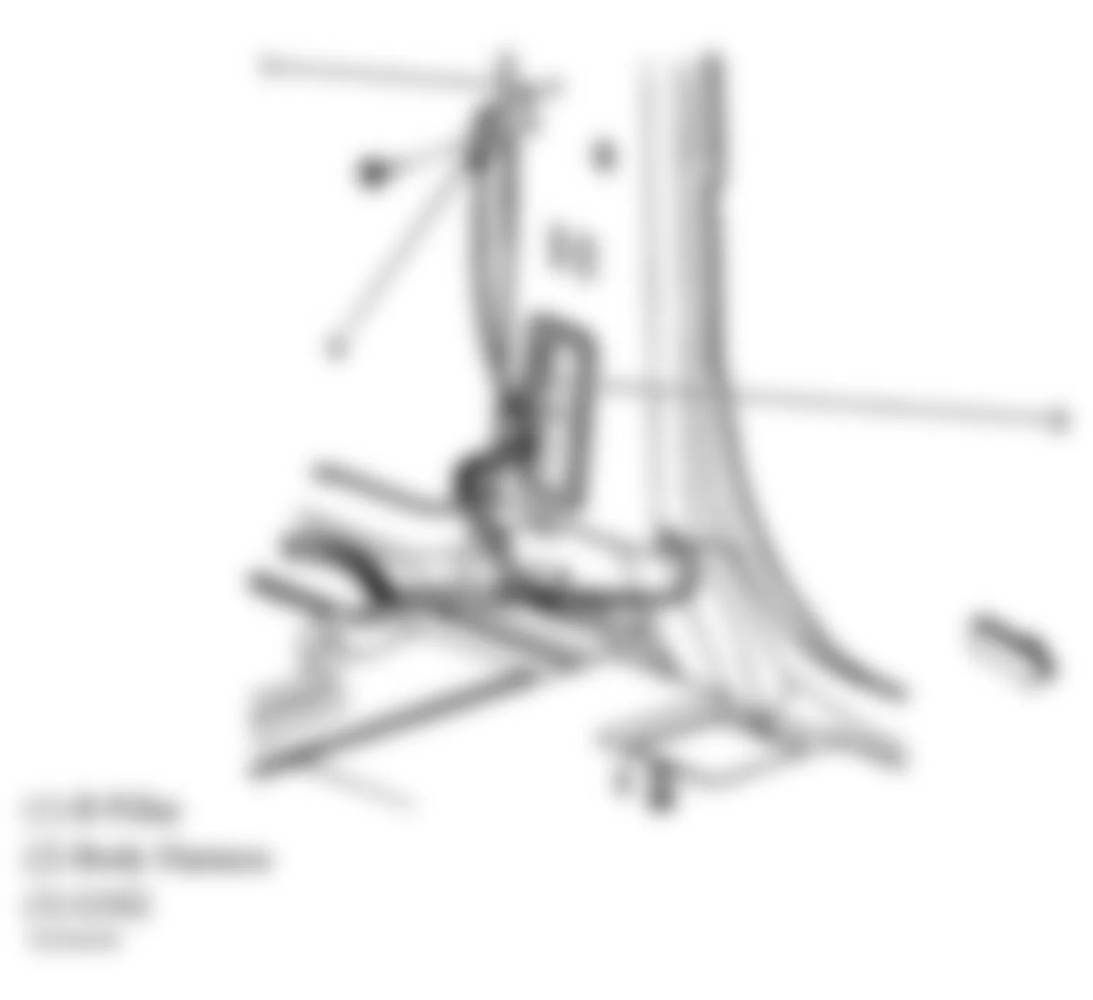
Fig. 7: Hummer H2 2009 - Component Locations - Right "B" Pillar
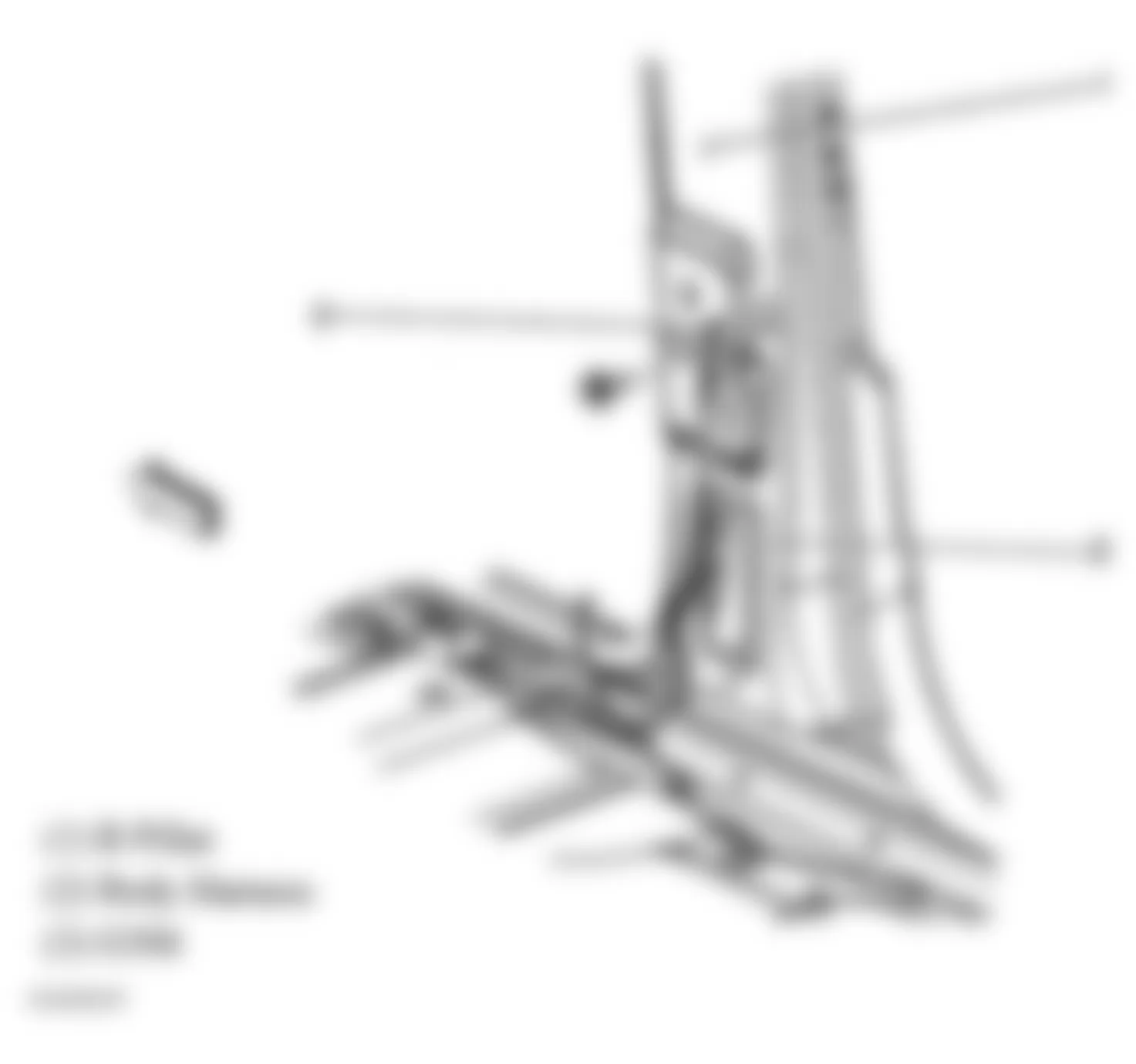
Fig. 8: Hummer H2 2009 - Component Locations - Rear Of Left Frame Rail
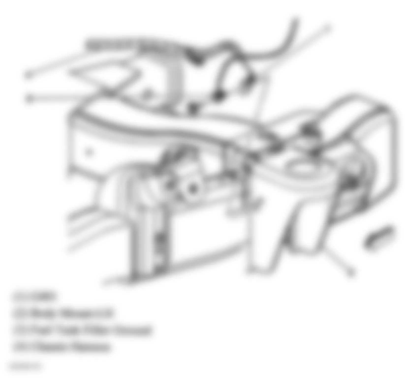
Fig. 9: Hummer H2 2009 - Component Locations - Rear Of Right Frame Rail
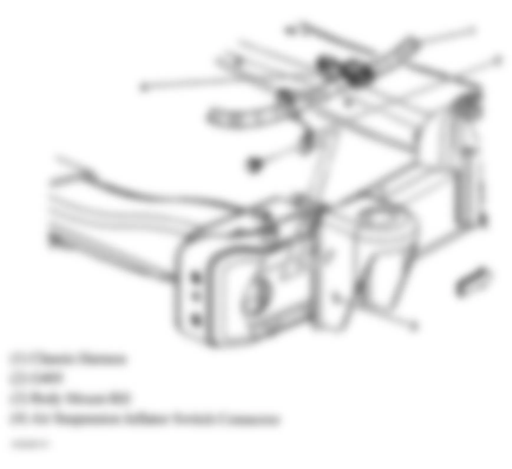
Fig. 10: Hummer H2 2009 - Component Locations - Right Rear Corner Of Vehicle
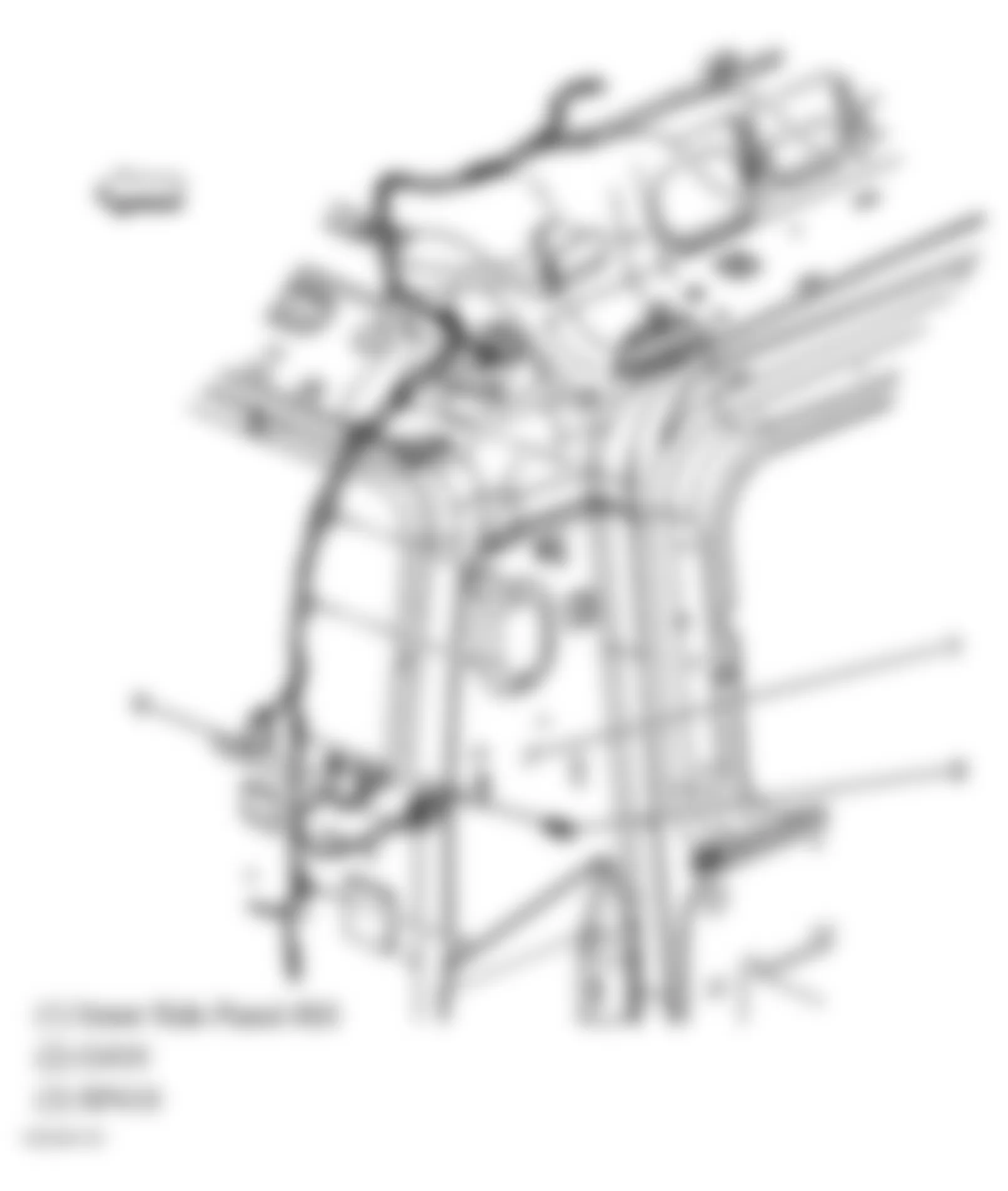
Fig. 11: Hummer H2 2009 - Component Locations - Lower Right Side Of Engine
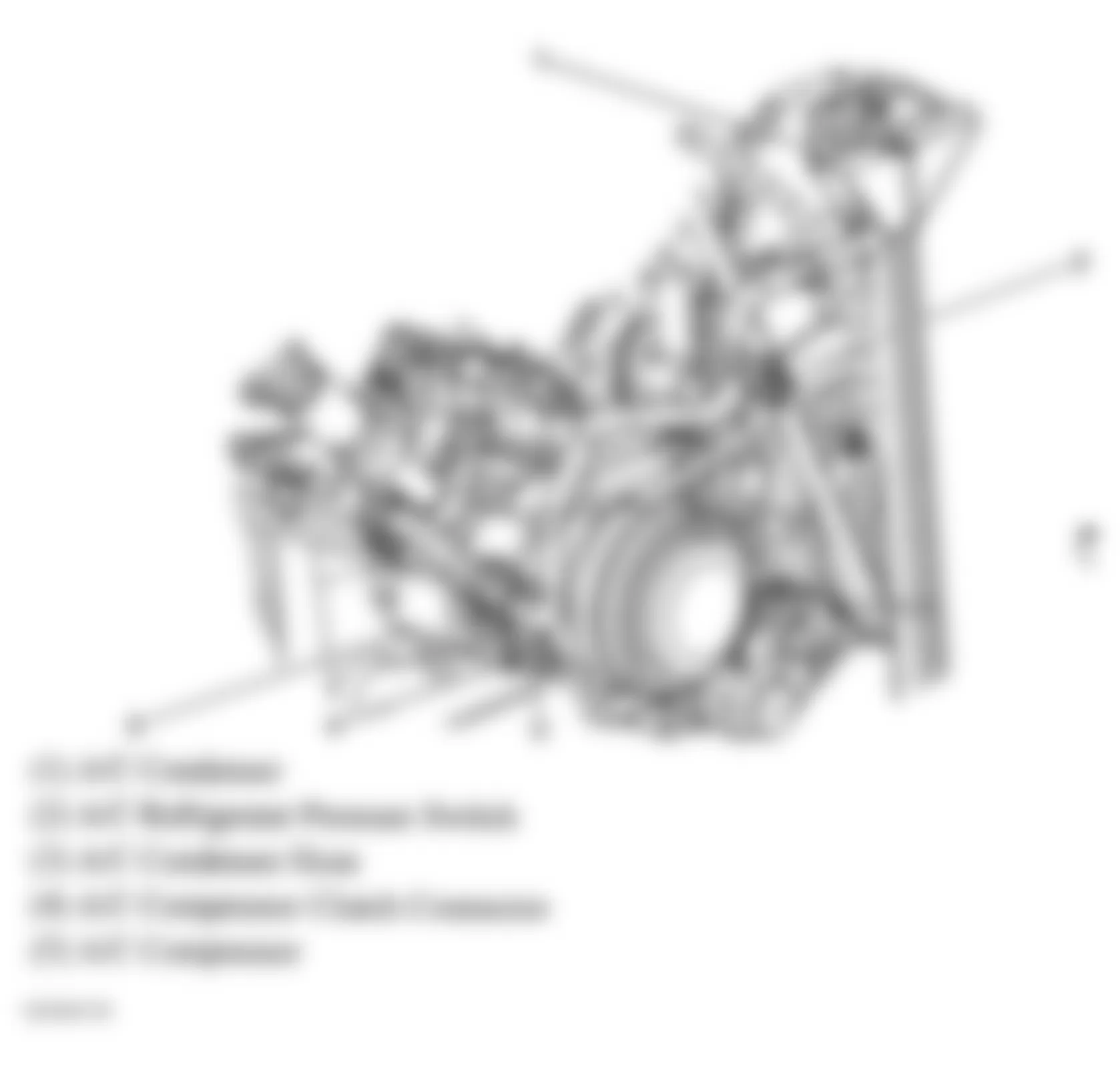
Fig. 12: Hummer H2 2009 - Component Locations - Steering Column (1 Of 2)
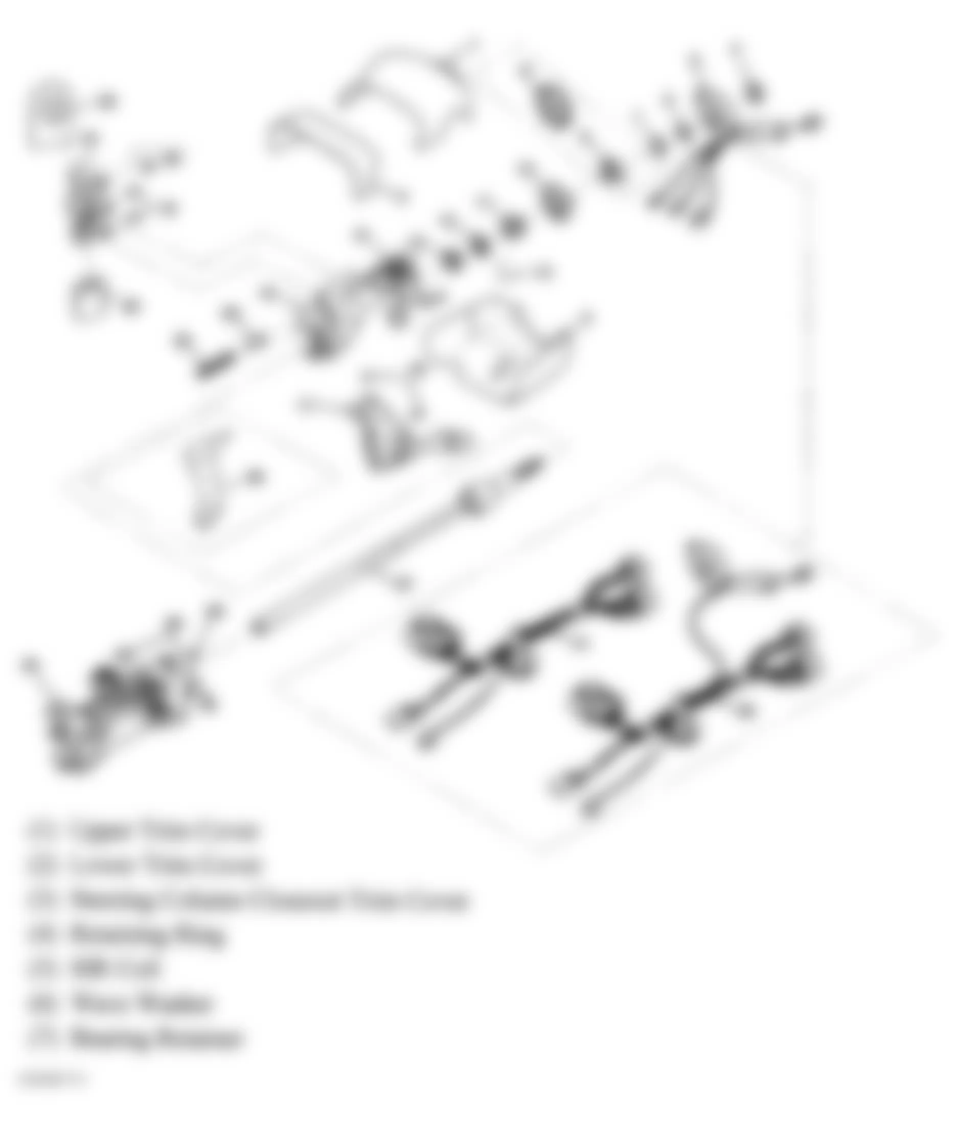
Fig. 13: Hummer H2 2009 - Component Locations - Steering Column (2 Of 2)
Fig. 14: Hummer H2 2009 - Component Locations - Air Suspension Components
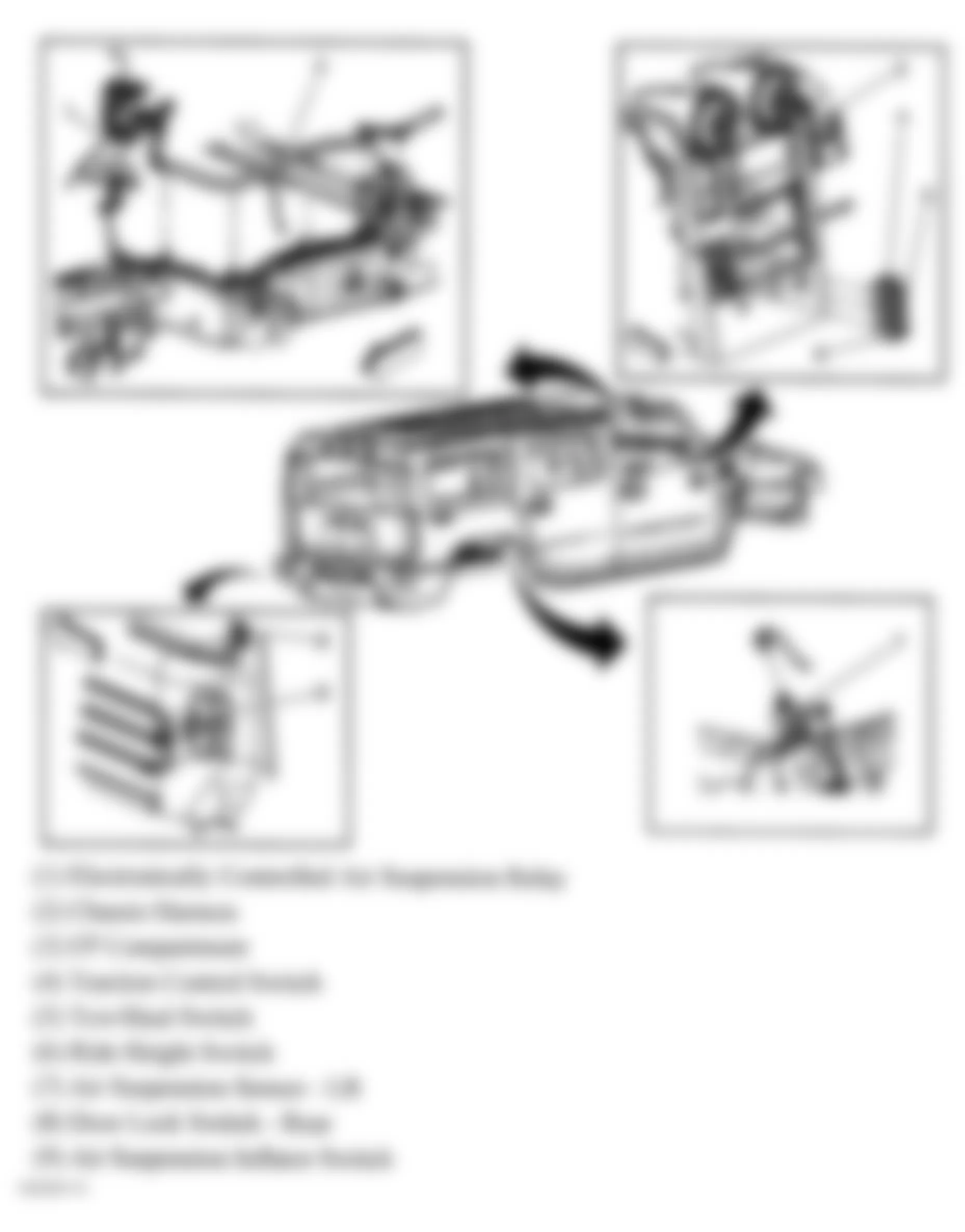
Fig. 15: Hummer H2 2009 - Component Locations - Locking Differential
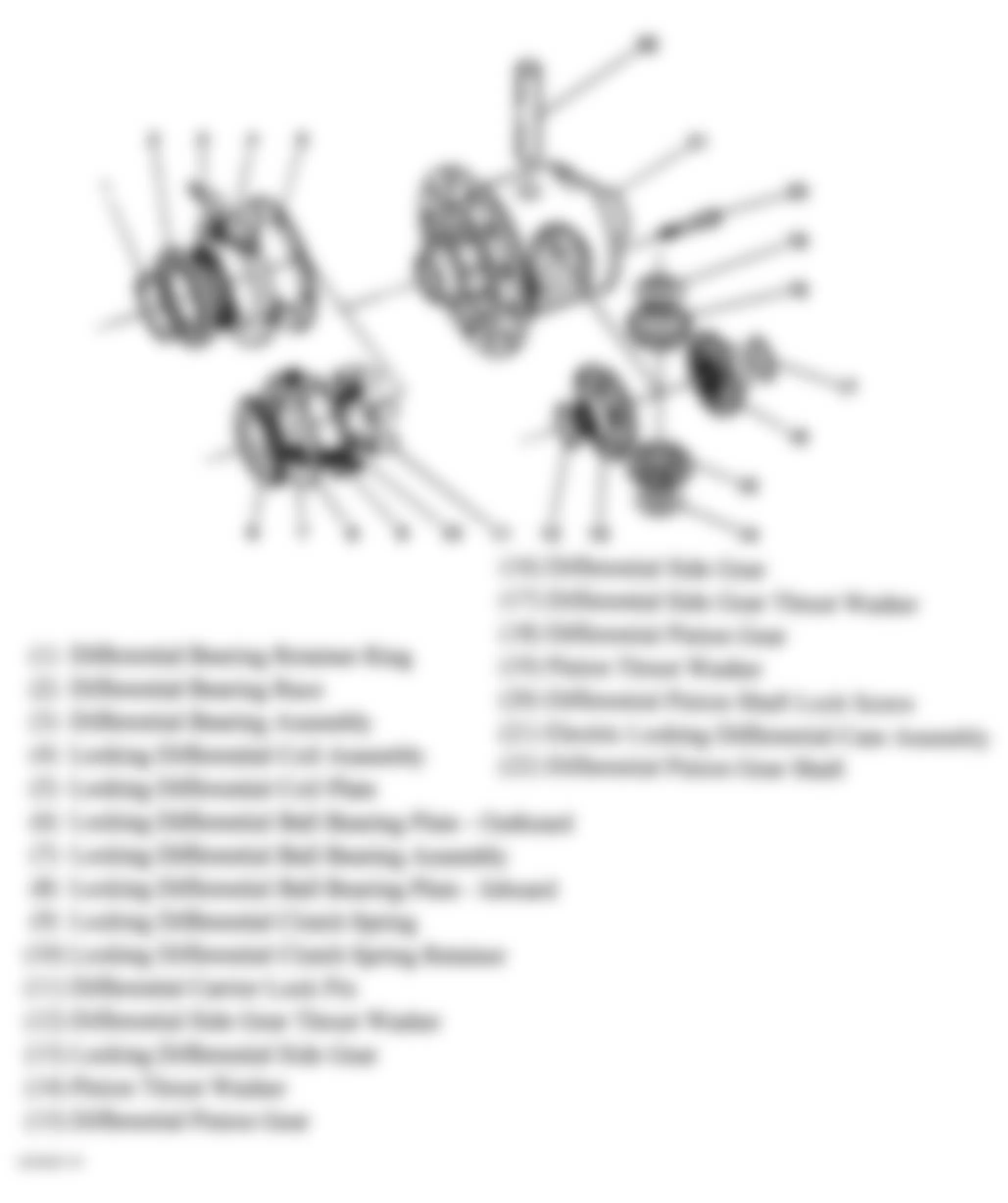
Fig. 16: Hummer H2 2009 - Component Locations - Rear Axle
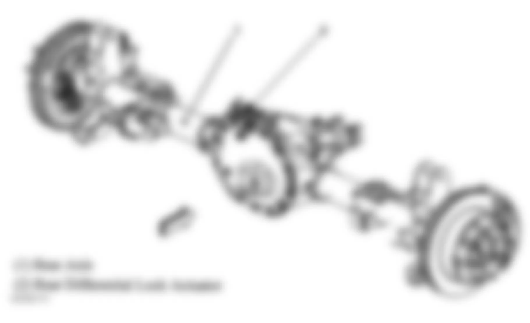
Fig. 17: Hummer H2 2009 - Component Locations - Transfer Case
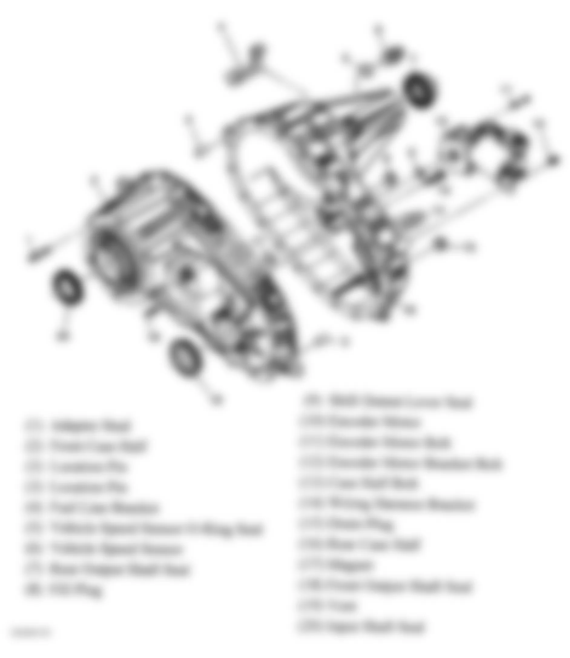
Fig. 18: Hummer H2 2009 - Component Locations - Rear Of Transmission
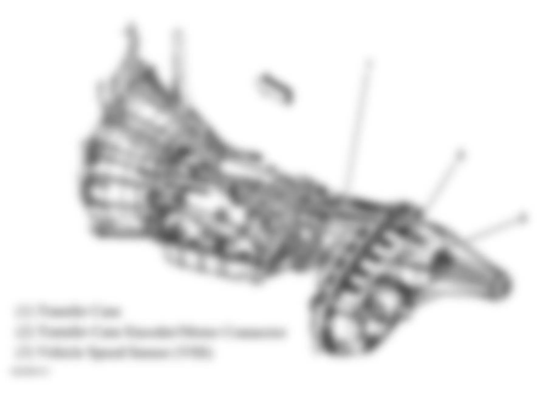
Fig. 19: Hummer H2 2009 - Component Locations - Lower Left Side Of Dash
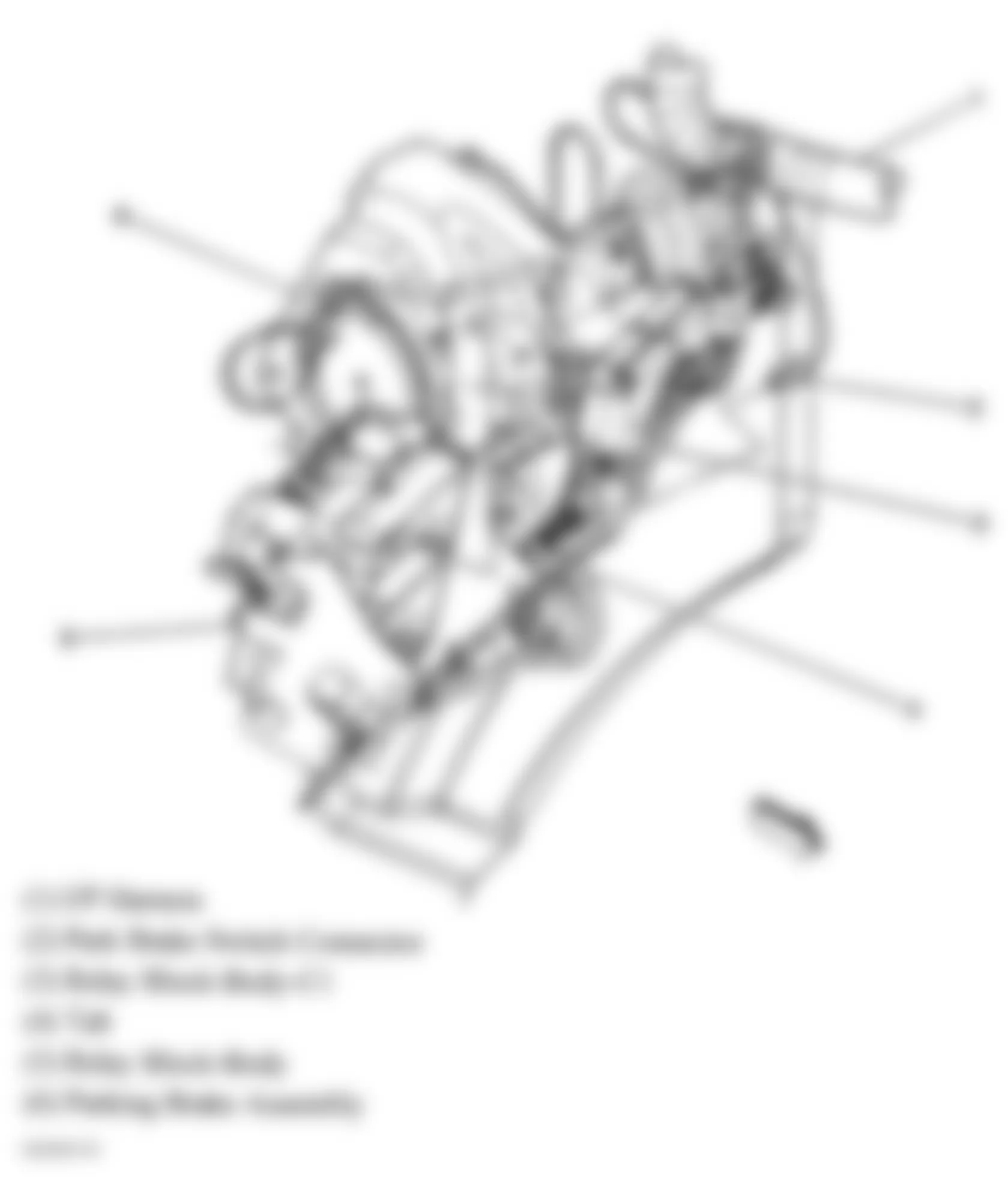
Fig. 20: Hummer H2 2009 - Component Locations - Lower Left Side Of Dash
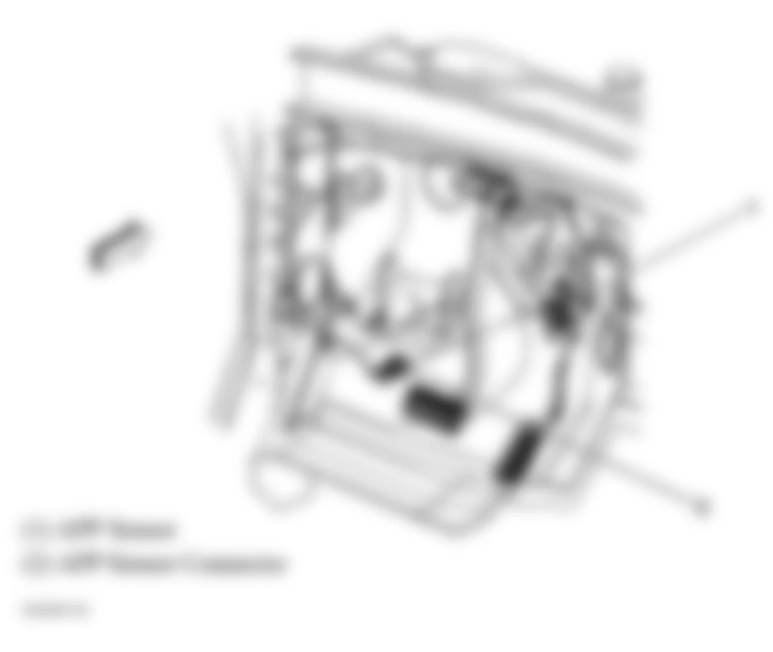
Fig. 21: Hummer H2 2009 - Component Locations - Lower Right Side Of Engine
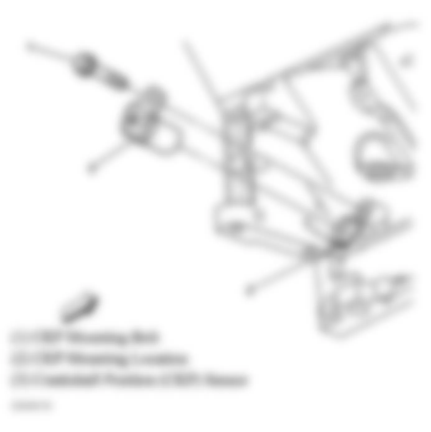
Fig. 22: Hummer H2 2009 - Component Locations - Engine Compartment & Lower Right Side Of Engine
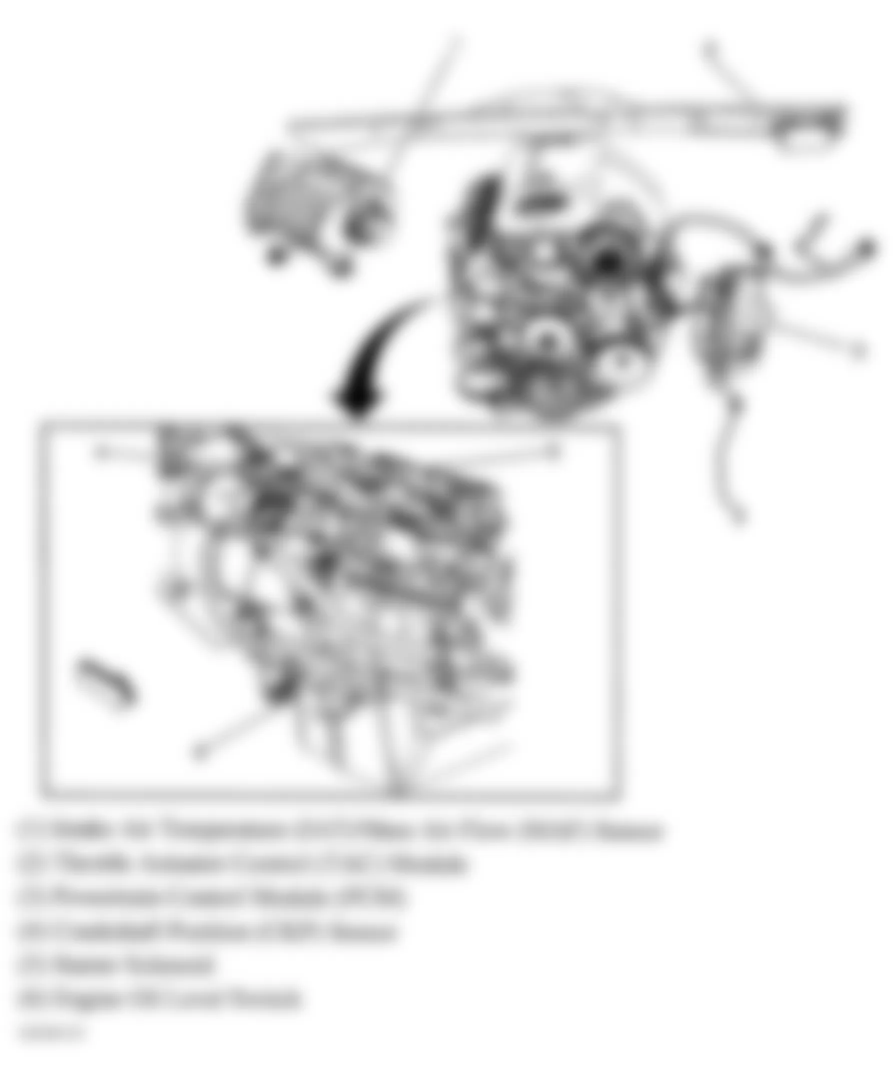
Fig. 23: Hummer H2 2009 - Component Locations - Right Rear, Left Rear & Front Of Engine
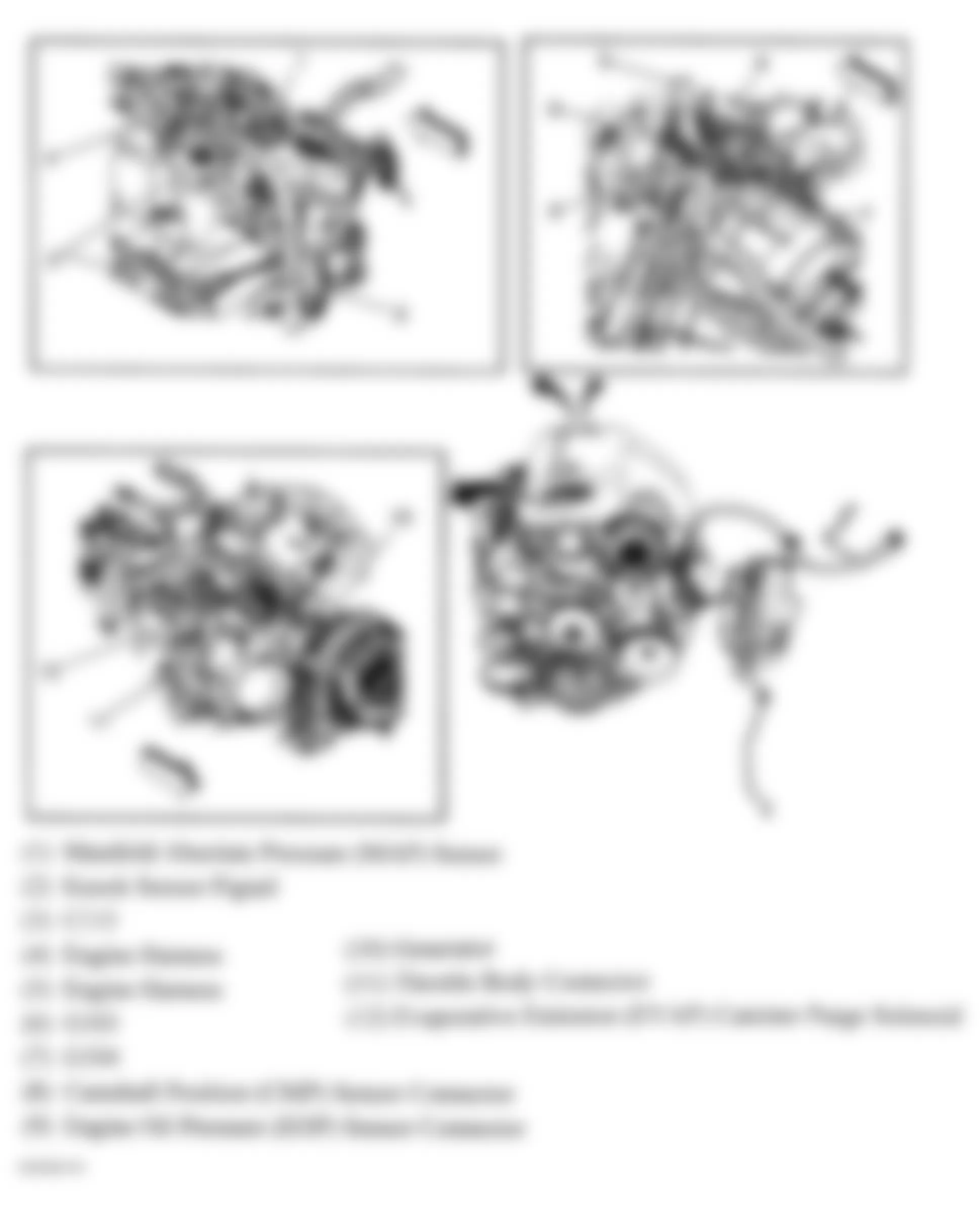
Fig. 24: Hummer H2 2009 - Component Locations - Frame
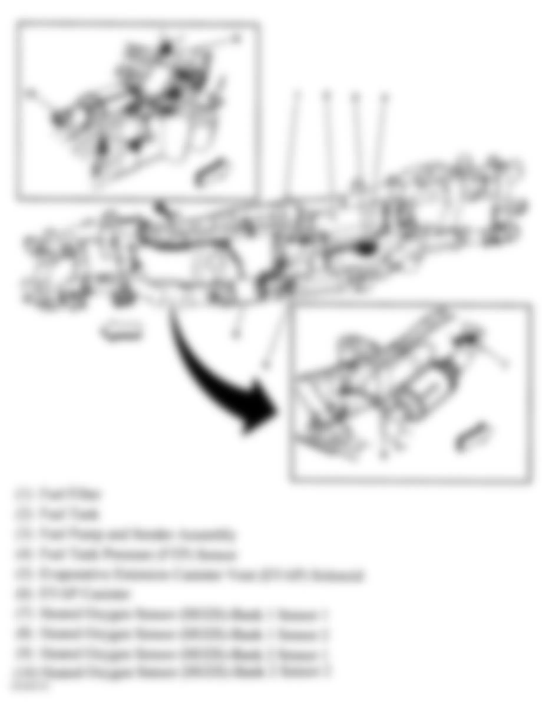
Fig. 25: Hummer H2 2009 - Component Locations - Left Side Of Dash
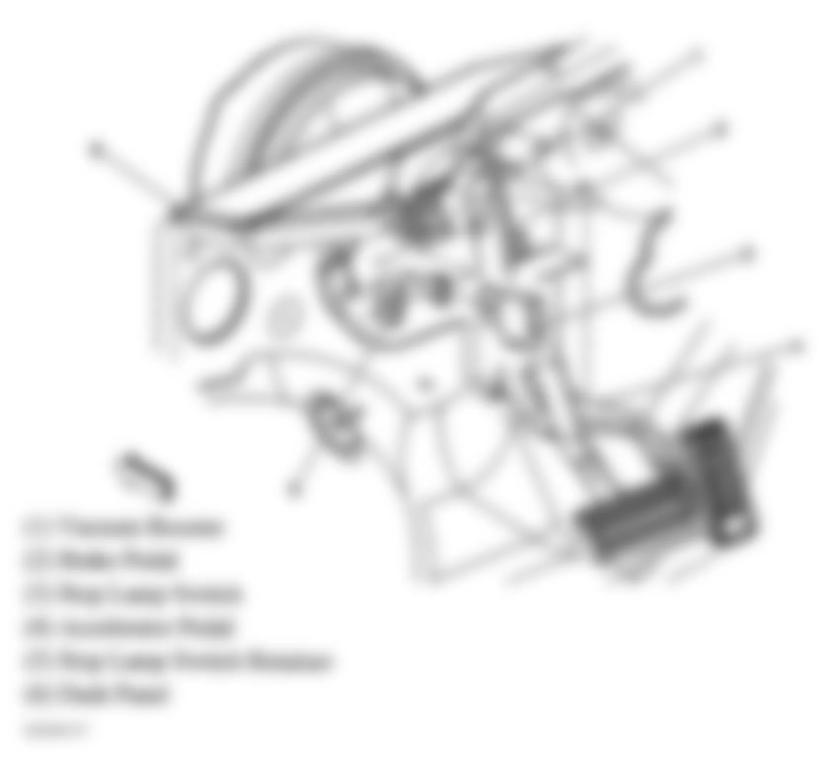
Fig. 26: Hummer H2 2009 - Component Locations - Transmission
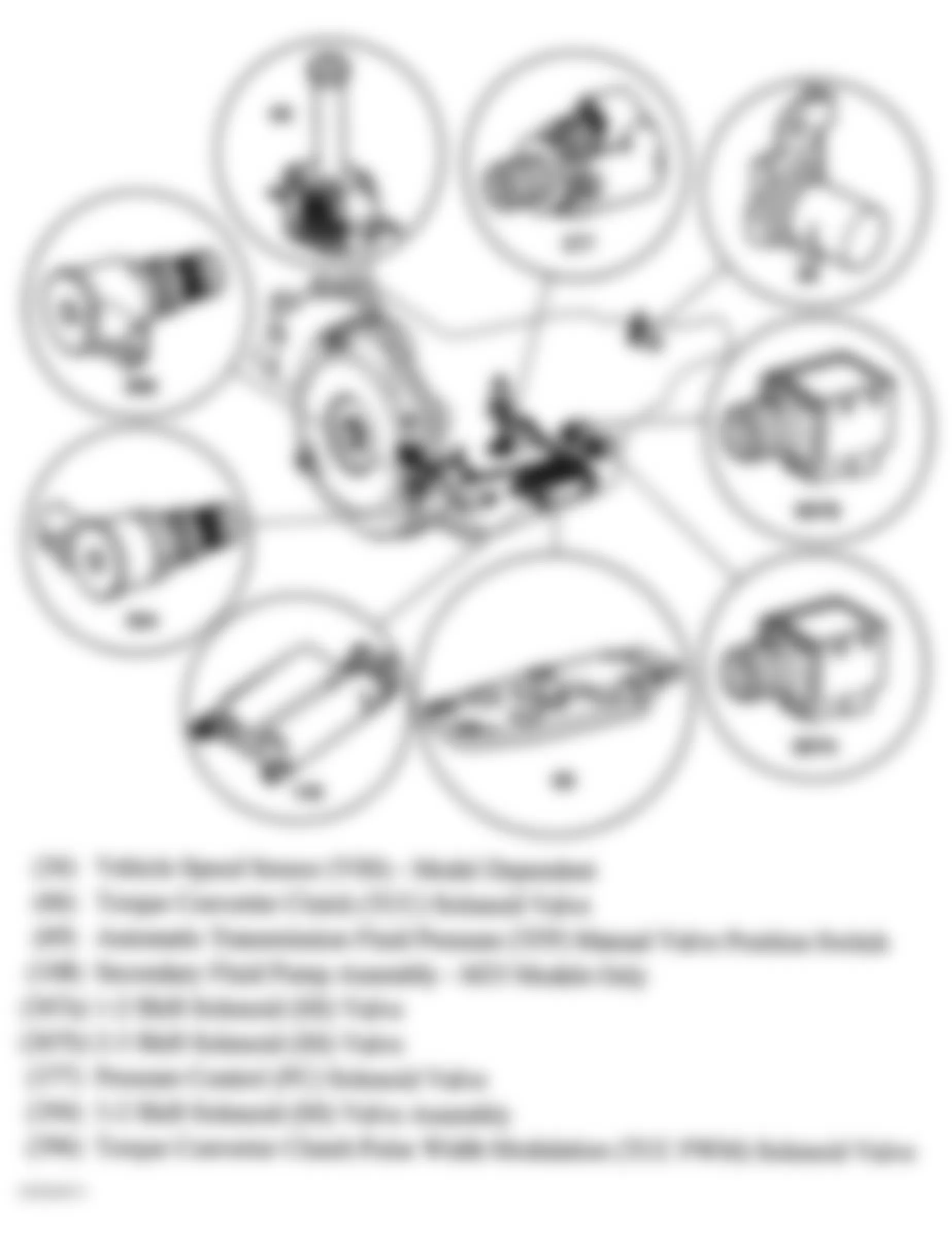
Fig. 27: Hummer H2 2009 - Component Locations - Front Of Roof
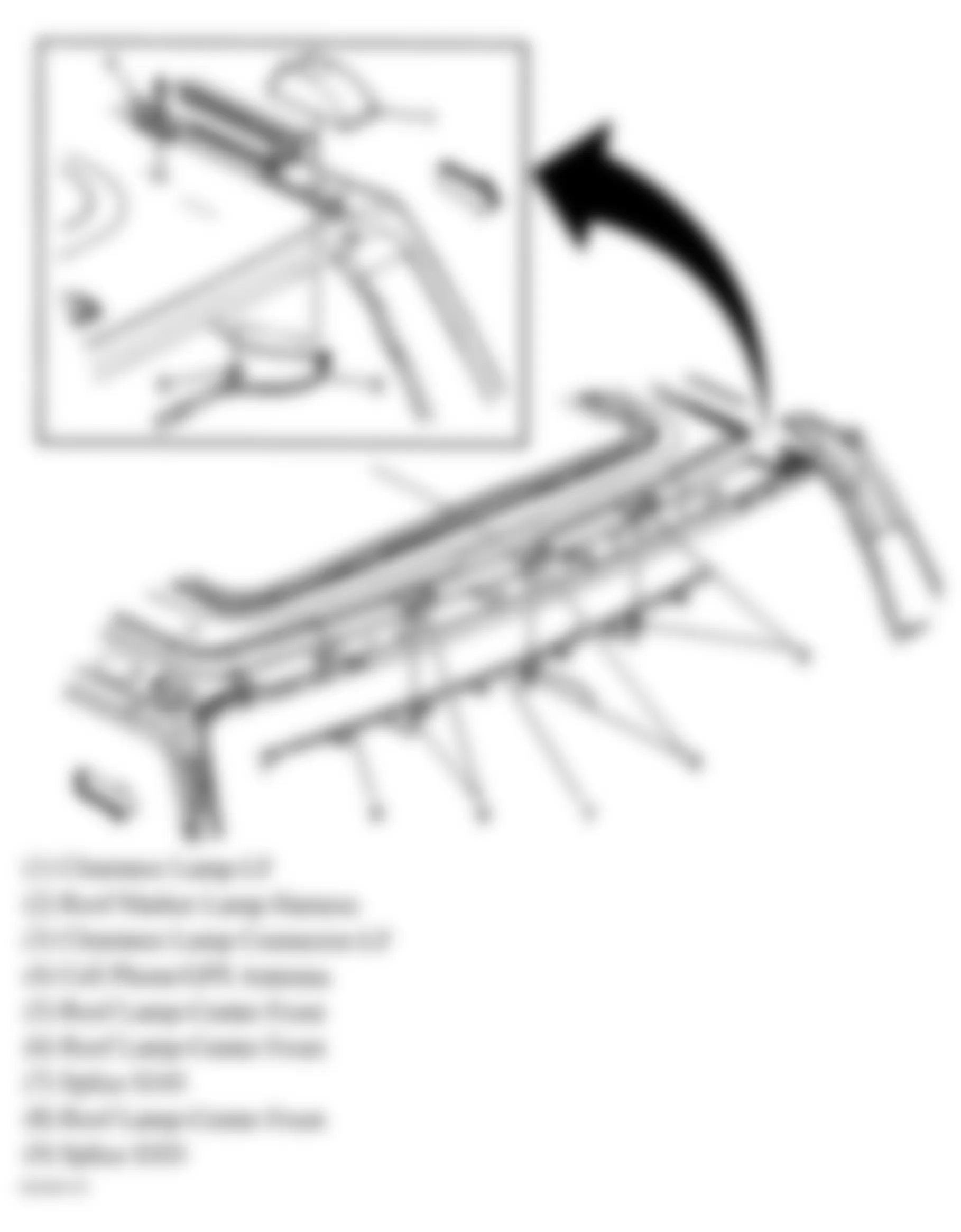
Fig. 28: Hummer H2 2009 - Component Locations - Driver Door
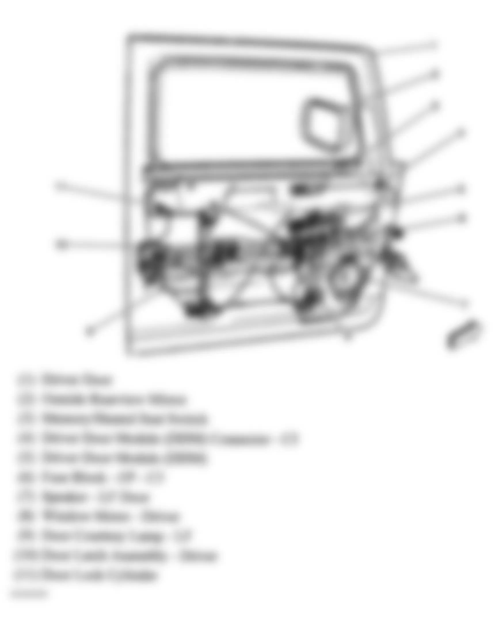
Fig. 29: Hummer H2 2009 - Component Locations - Passenger Door
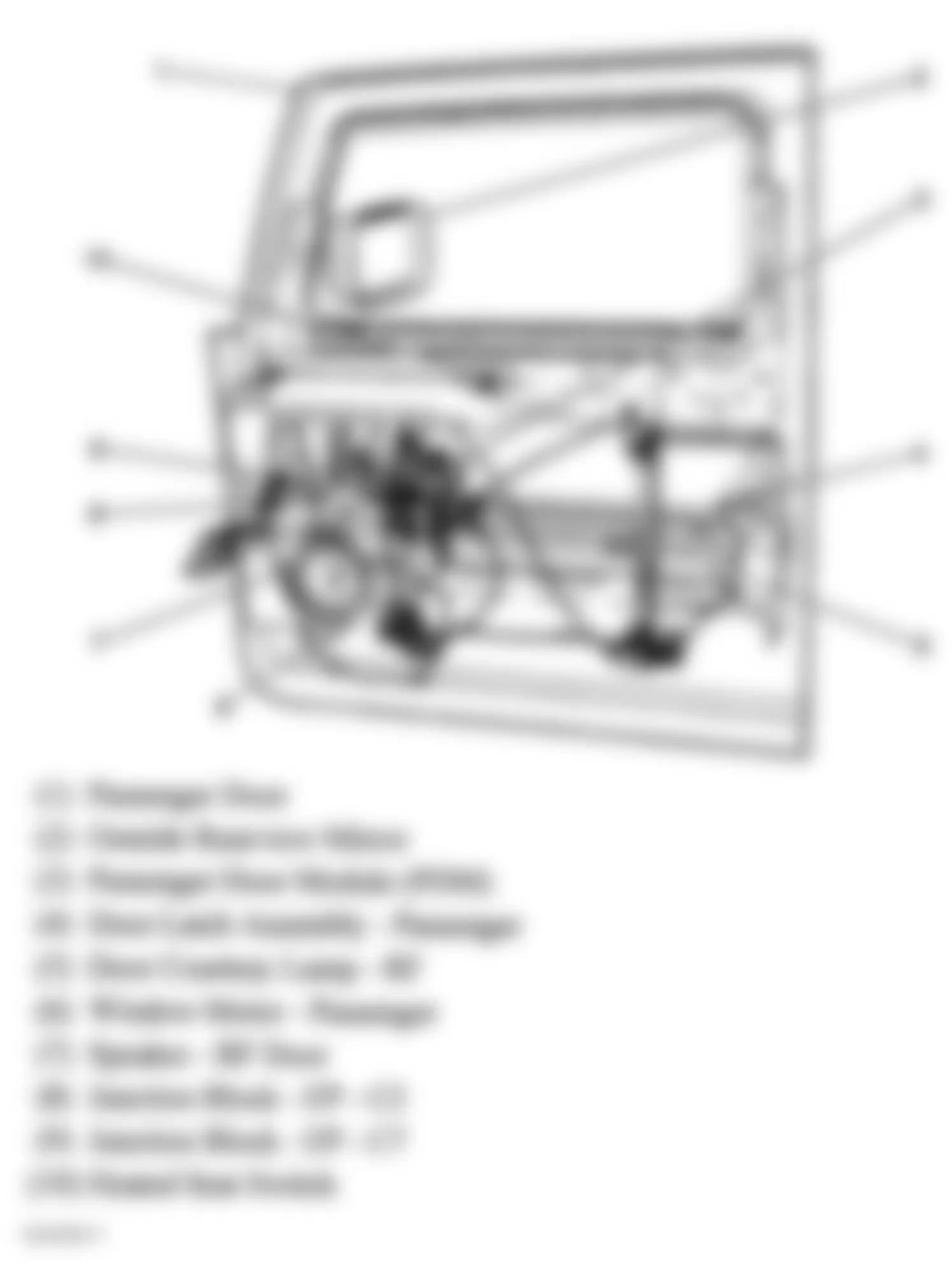
Fig. 30: Hummer H2 2009 - Component Locations - Left Rear Door
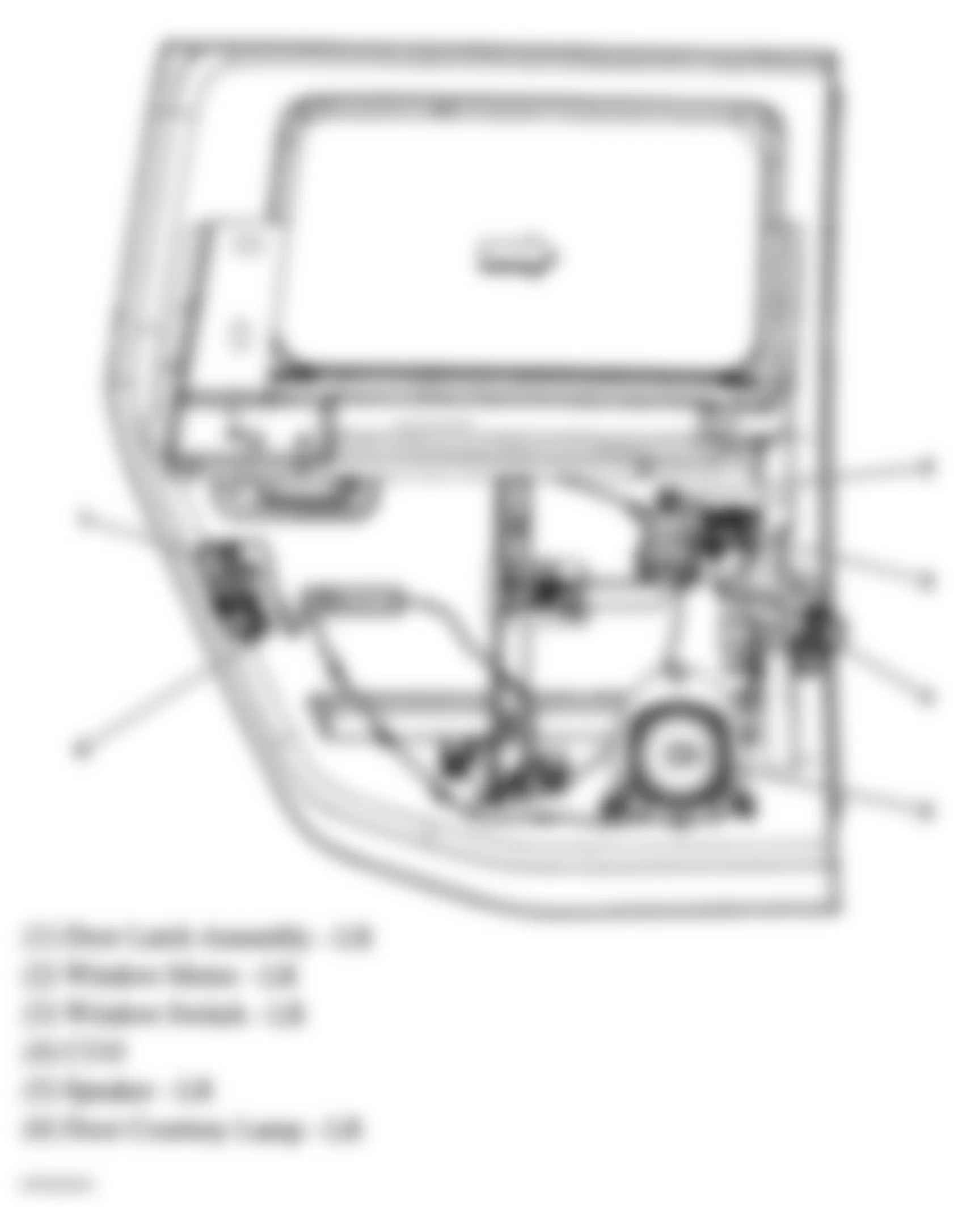
Fig. 31: Hummer H2 2009 - Component Locations - Liftgate
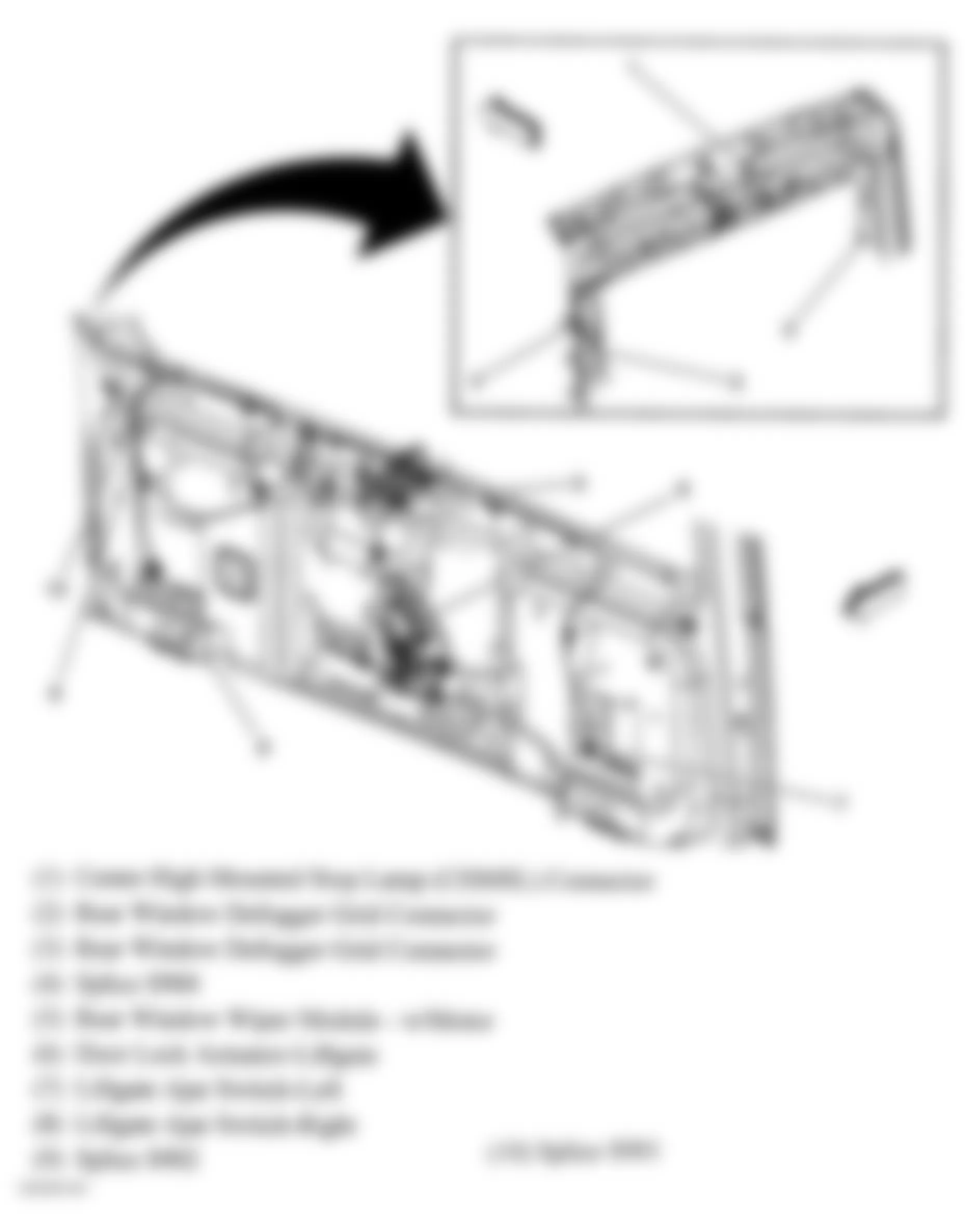
Fig. 32: Hummer H2 2009 - Component Locations - Front Of Vehicle
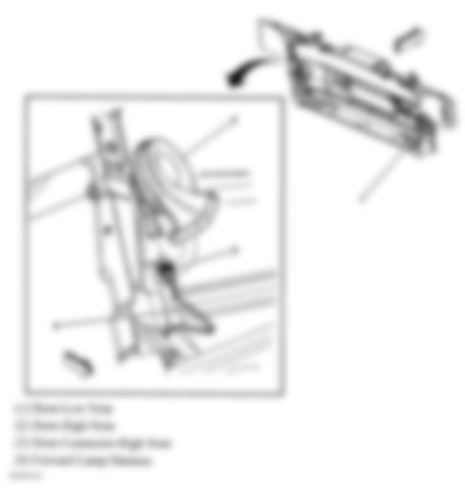
Fig. 33: Hummer H2 2009 - Component Locations - Under Driver Seat
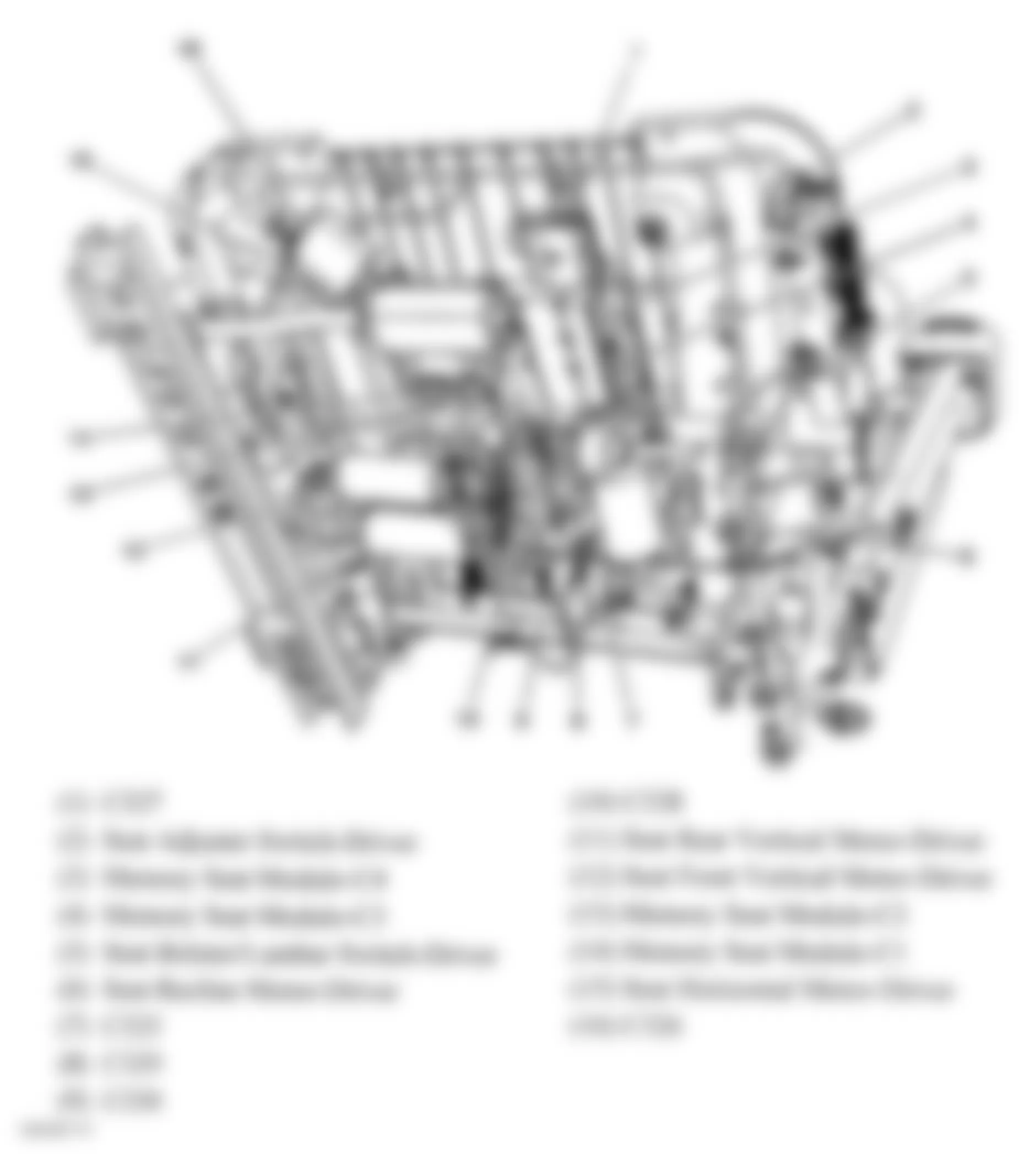
Fig. 34: Hummer H2 2009 - Component Locations - Wiper/Washer System Components
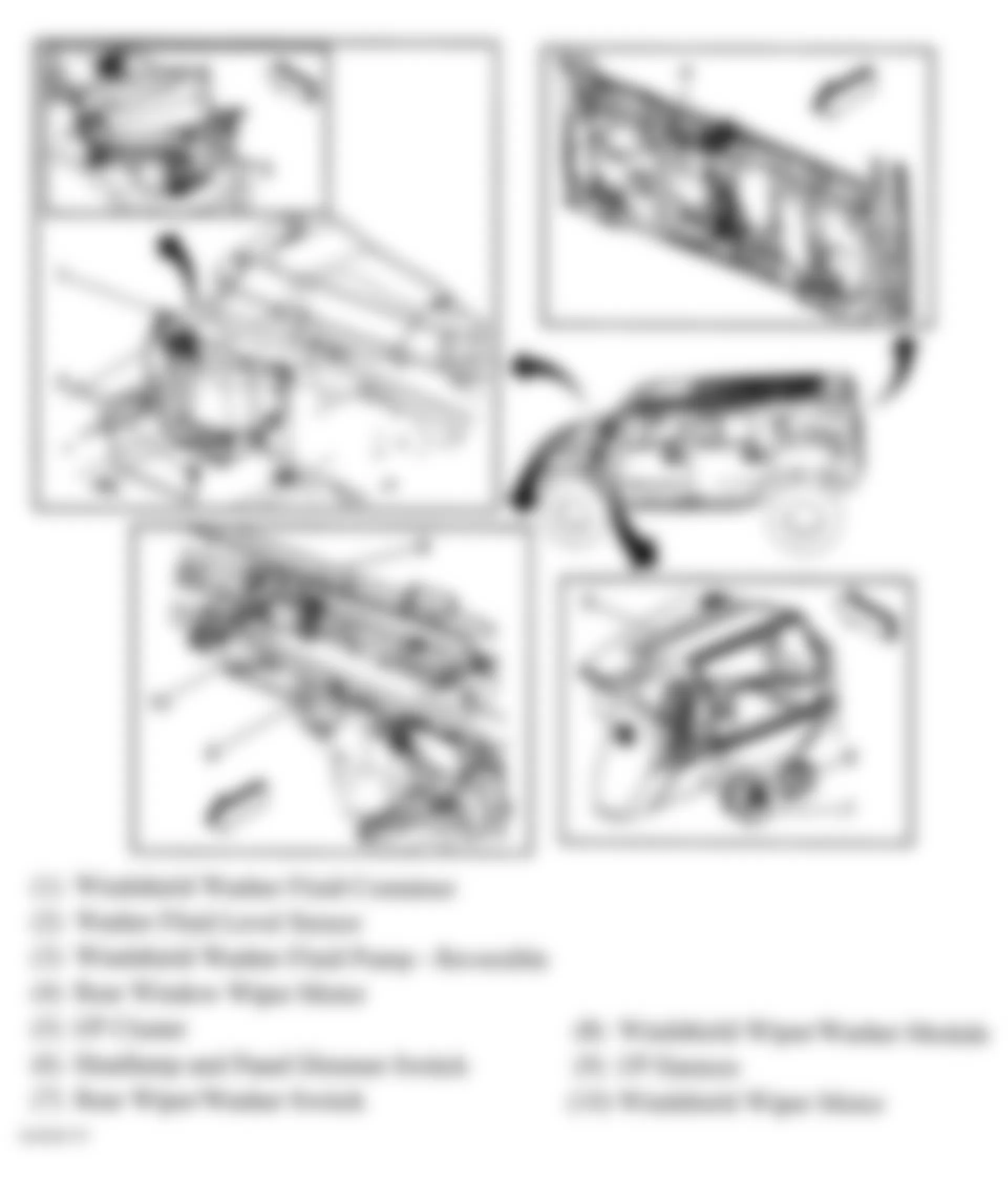
Fig. 35: Hummer H2 2009 - Component Locations - Top Of Liftgate
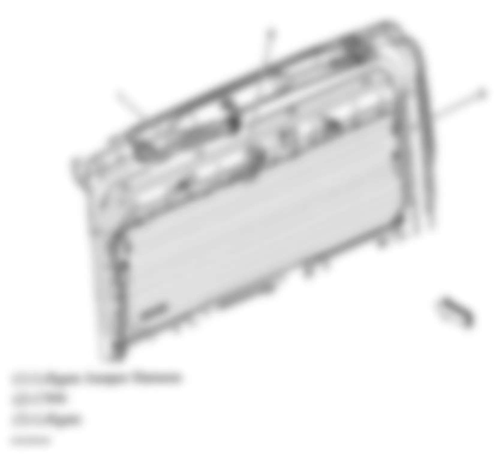
Fig. 36: Hummer H2 2009 - Component Locations - Right Rear Door
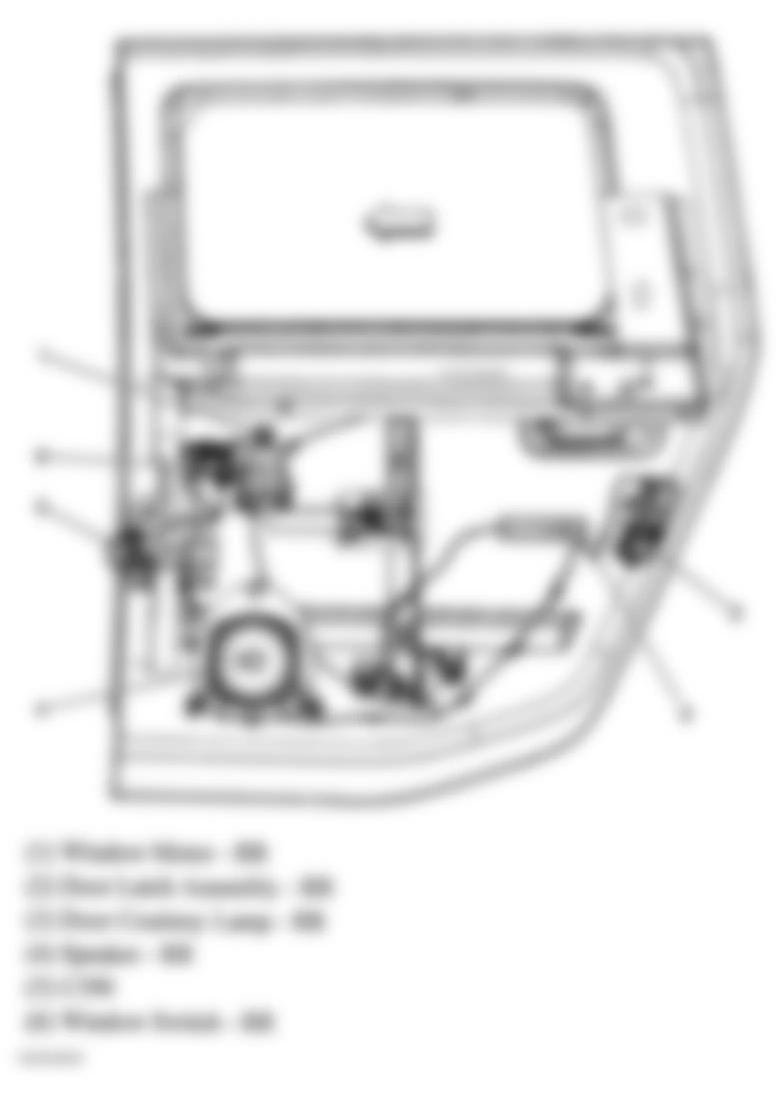
Fig. 37: Hummer H2 2009 - Component Locations - Engine Electrical Components
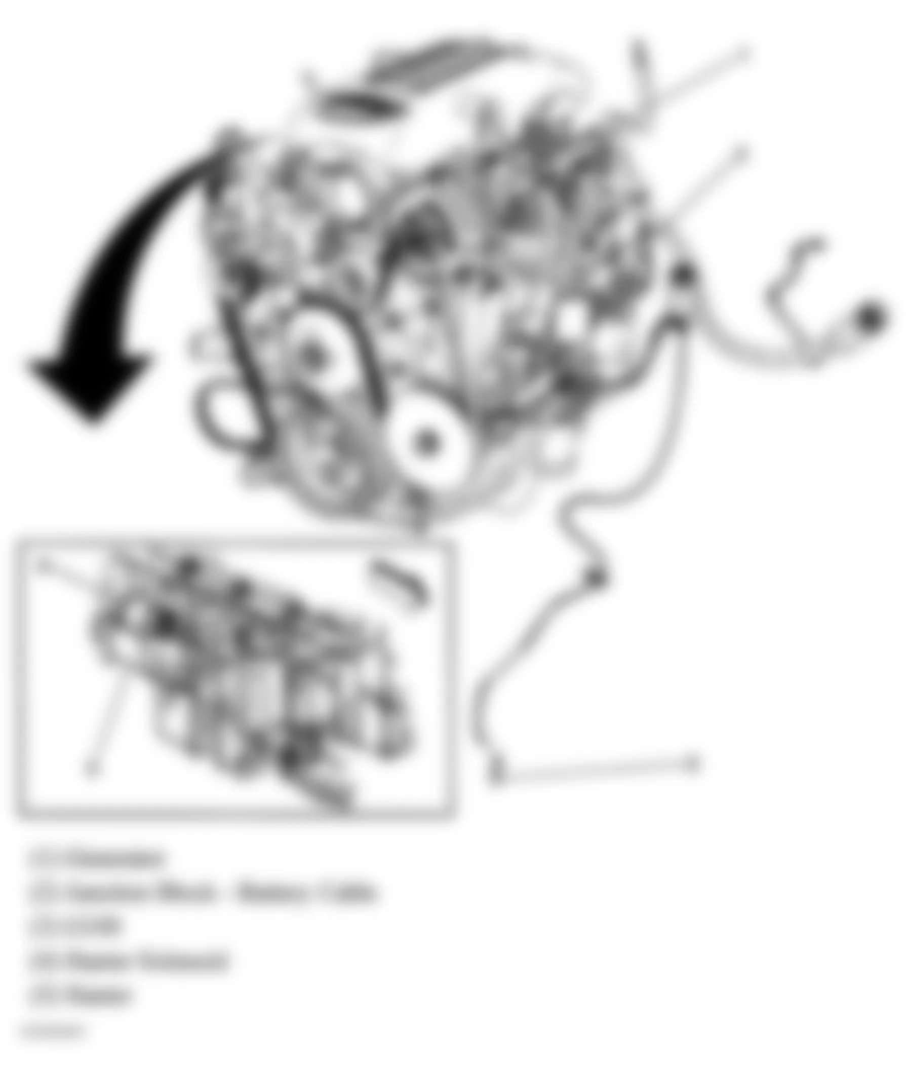
Fig. 38: Hummer H2 2009 - Component Locations - Under Hood Fuse Block
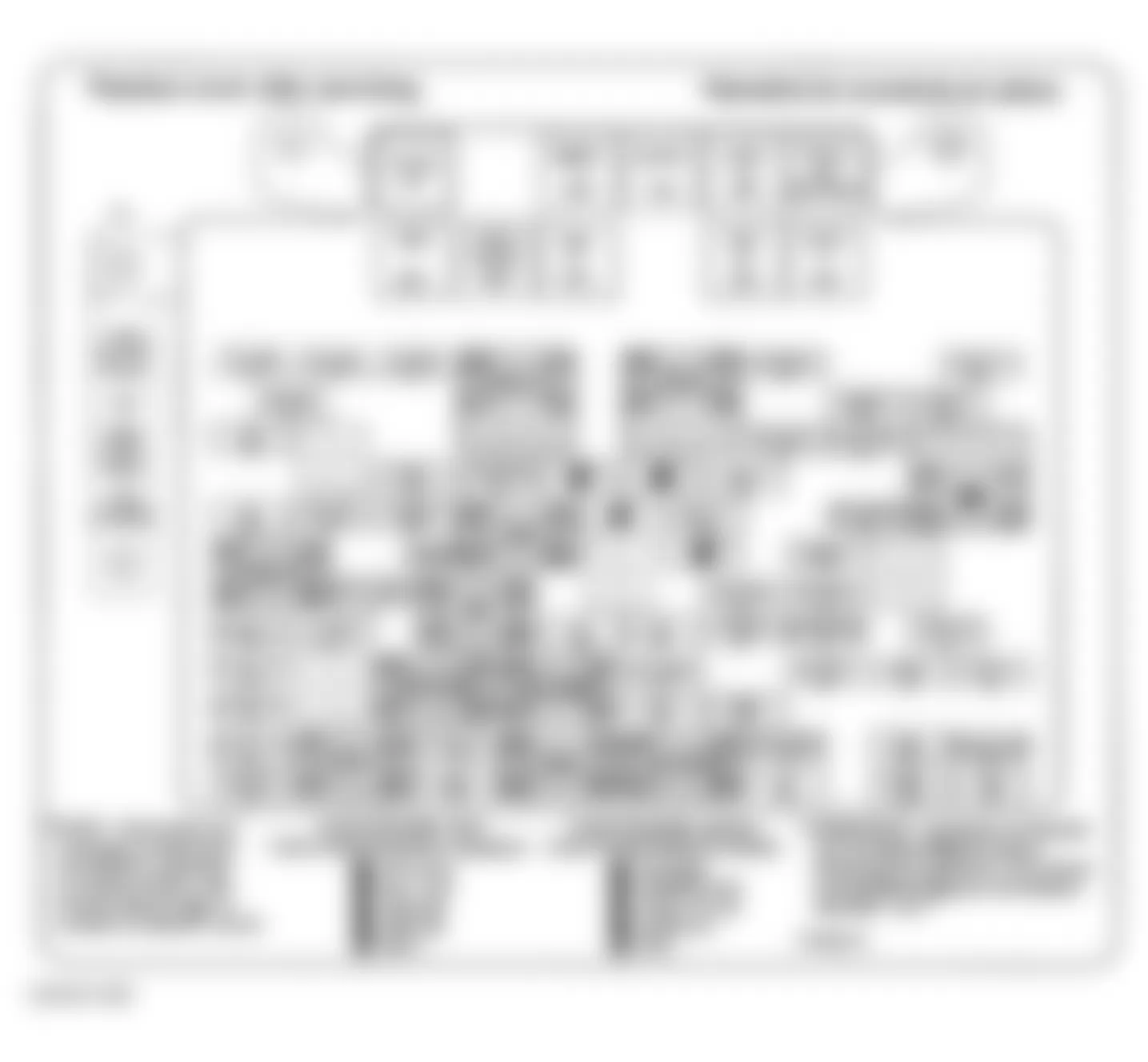
Fig. 39: Hummer H2 2009 - Component Locations - I/P Relay Block
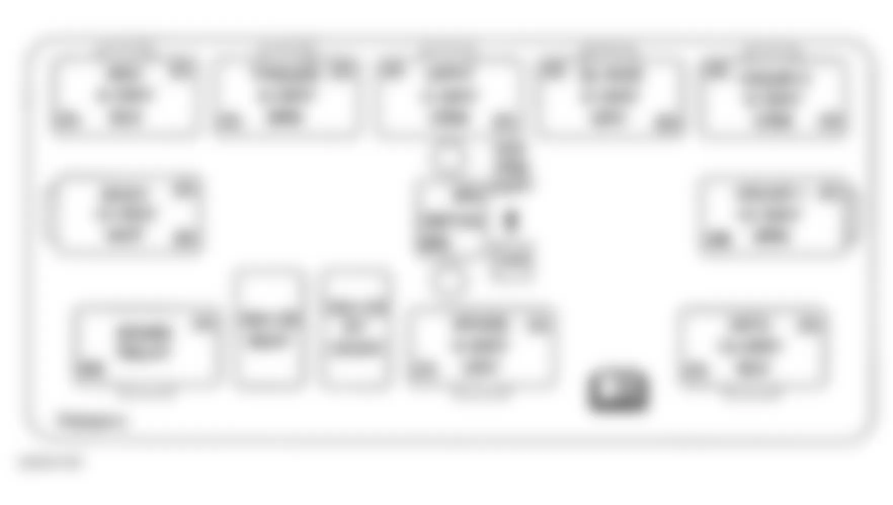
Fig. 40: Hummer H2 2009 - Component Locations - I/P Fuse Block
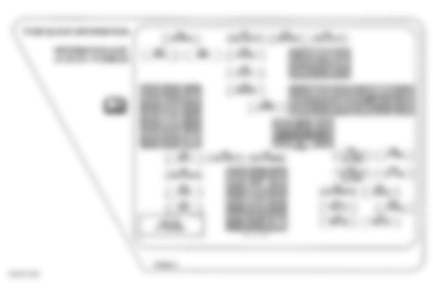
Fig. 41: Hummer H2 2009 - Component Locations - Front Of Engine Compartment
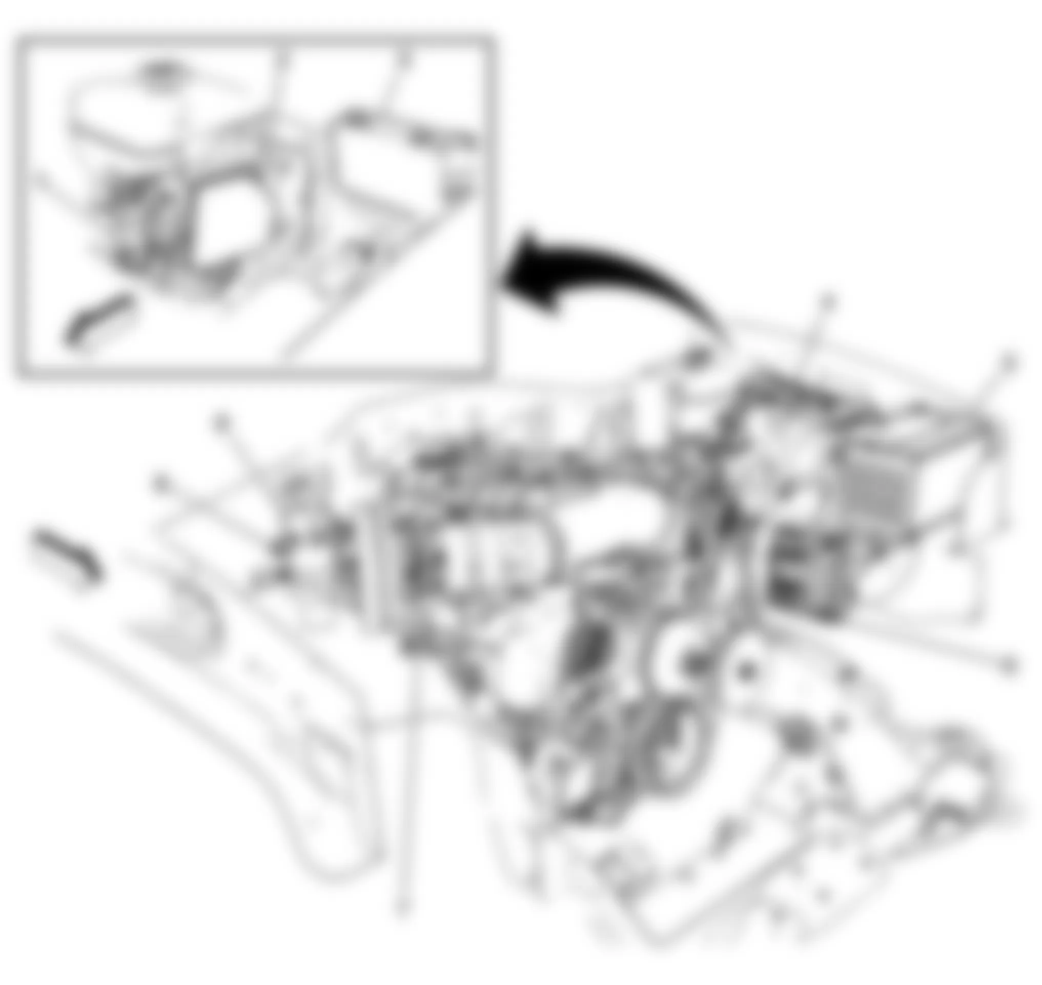
Fig. 42: Hummer H2 2009 - Component Locations - Rear Compartment Components
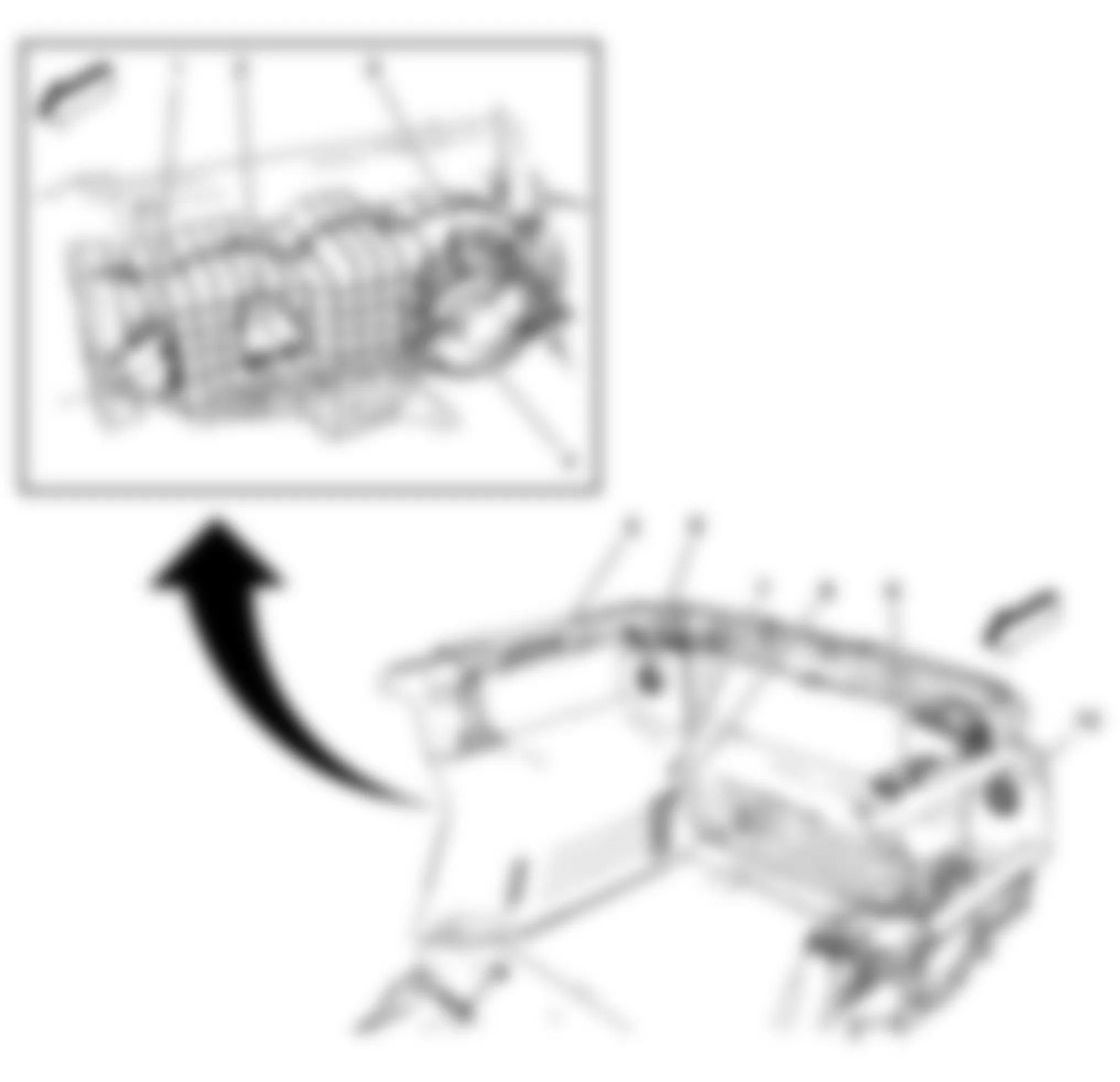
Fig. 43: Hummer H2 2009 - Component Locations - Air Suspension Unit
Fig. 44: Hummer H2 2009 - Component Locations - Front Suspension
Fig. 45: Hummer H2 2009 - Component Locations - Rear Suspension

Fig. 46: Hummer H2 2009 - Component Locations - HVAC Module
Fig. 47: Hummer H2 2009 - Component Locations - Engine Compartment
Fig. 48: Hummer H2 2009 - Component Locations - Headliner
Fig. 49: Hummer H2 2009 - Component Locations - Instrument Panel
Fig. 50: Hummer H2 2009 - Component Locations - Instrument Panel
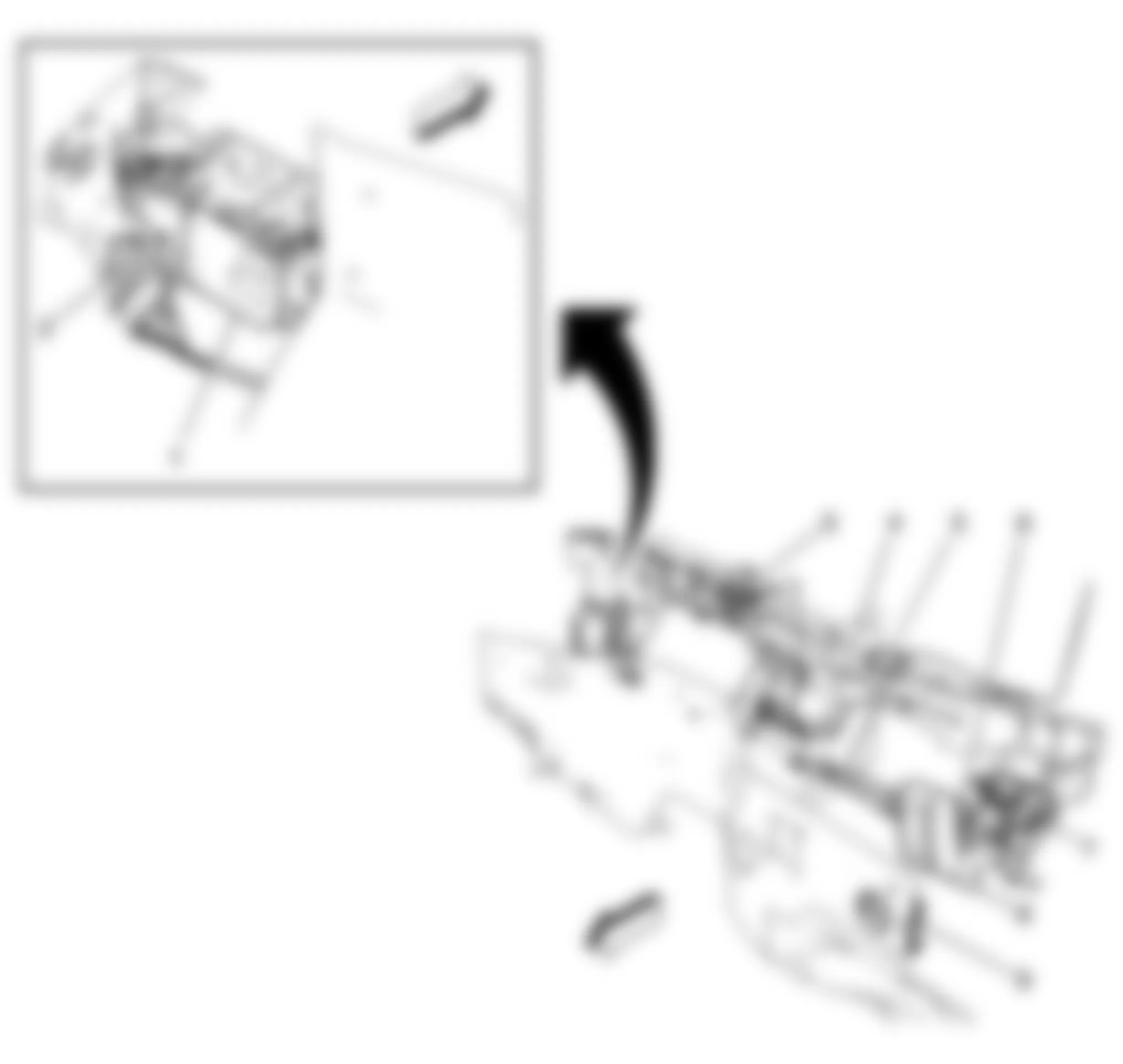
Fig. 51: Hummer H2 2009 - Component Locations - Inside Transmission Components
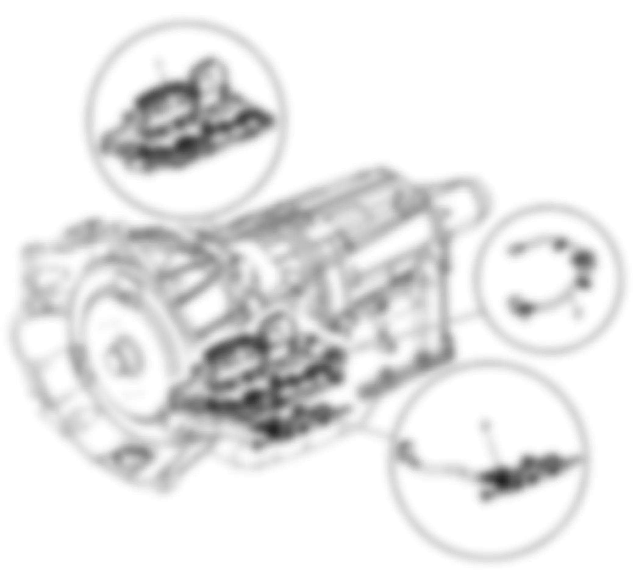
Fig. 52: Hummer H2 2009 - Component Locations - Floor Console Components
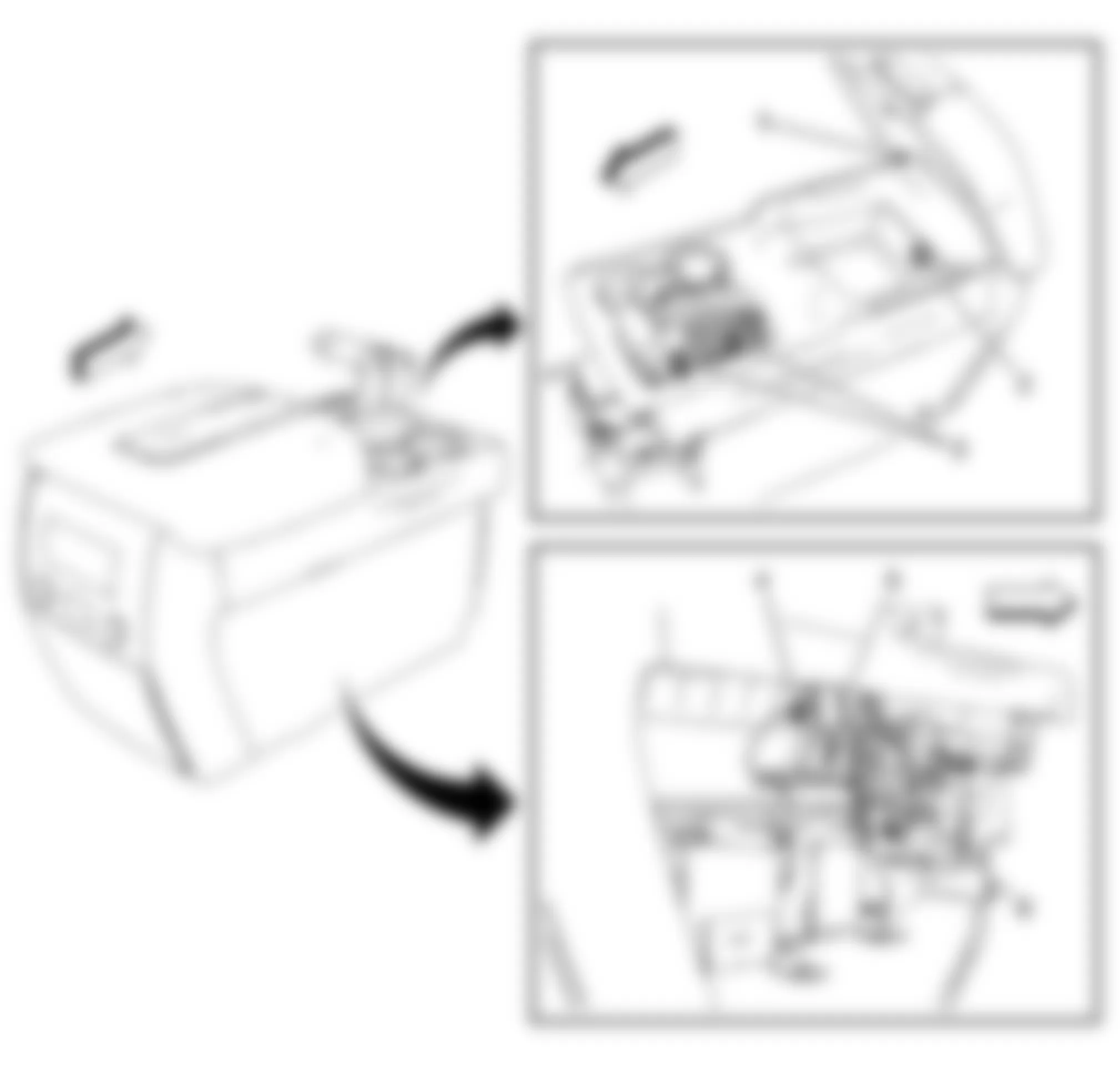
Fig. 53: Hummer H2 2009 - Component Locations - Right Rear Of Engine
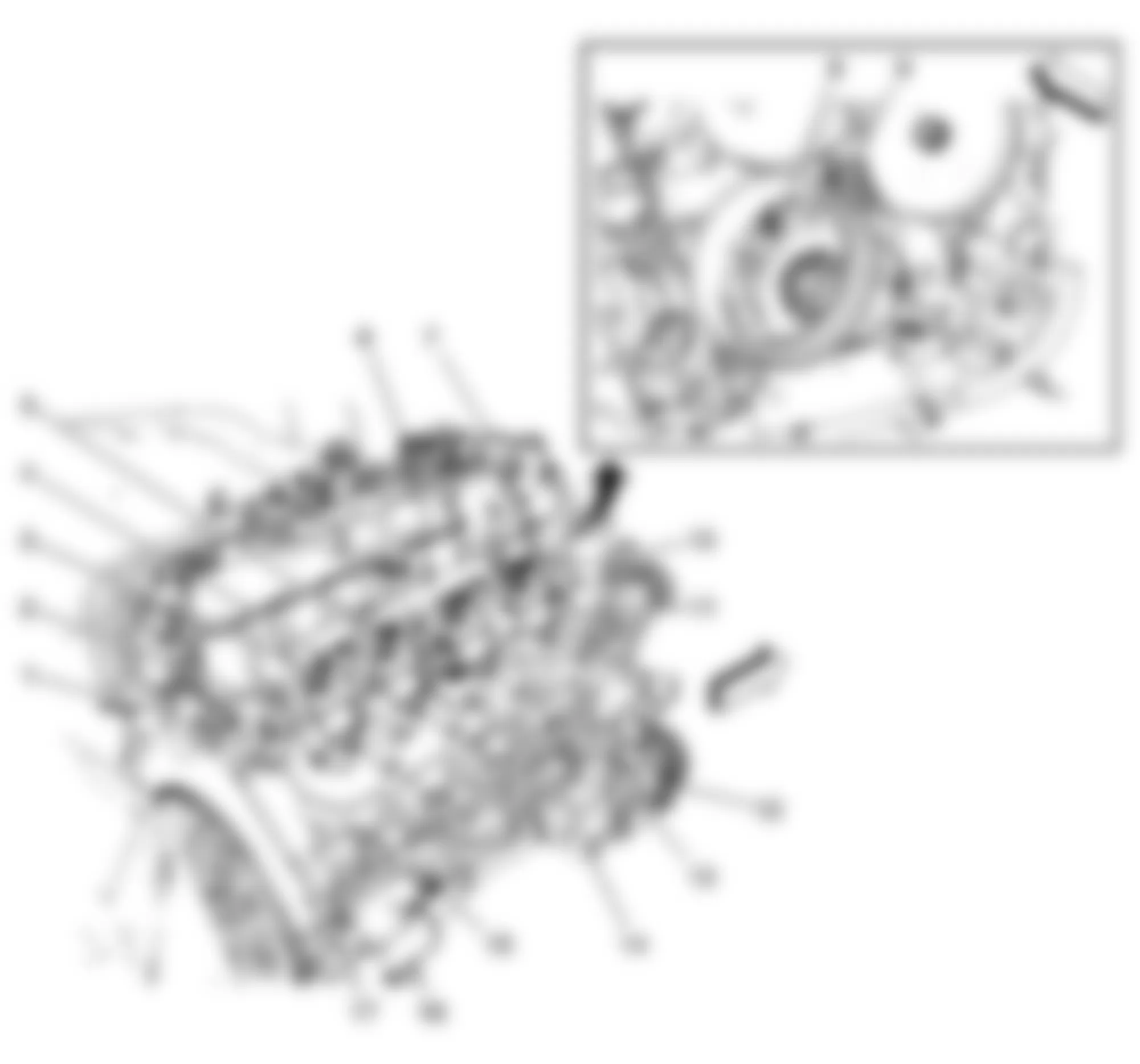
Fig. 54: Hummer H2 2009 - Component Locations - Rear Suspension
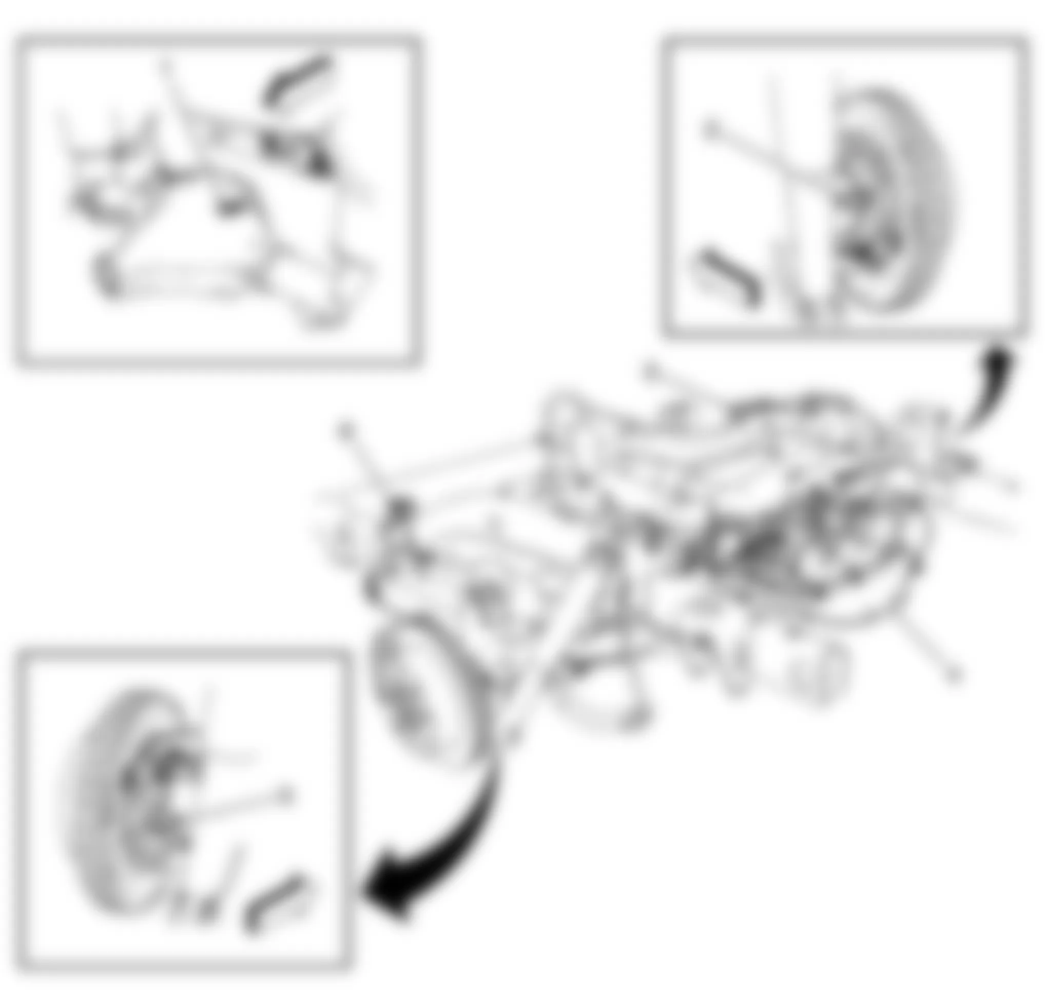
Fig. 55: Hummer H2 2009 - Component Locations - Left Rear Of Engine
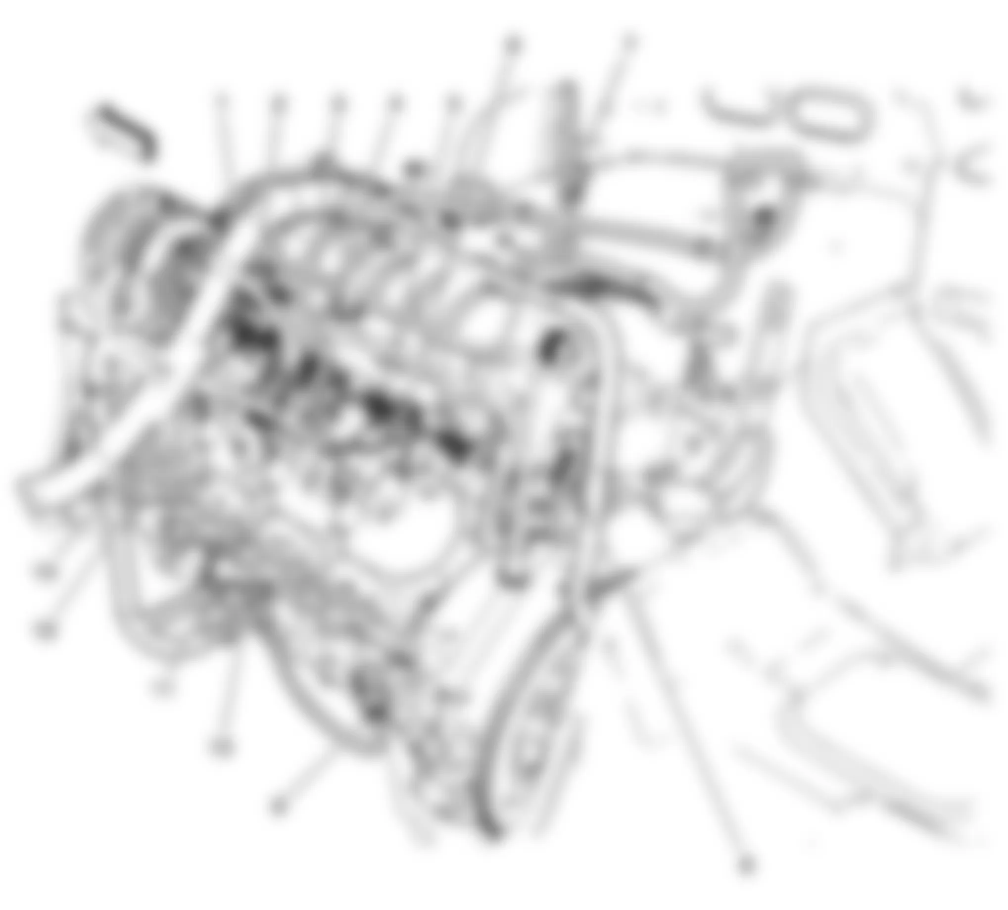
Fig. 56: Hummer H2 2009 - Component Locations - Fuel System Components
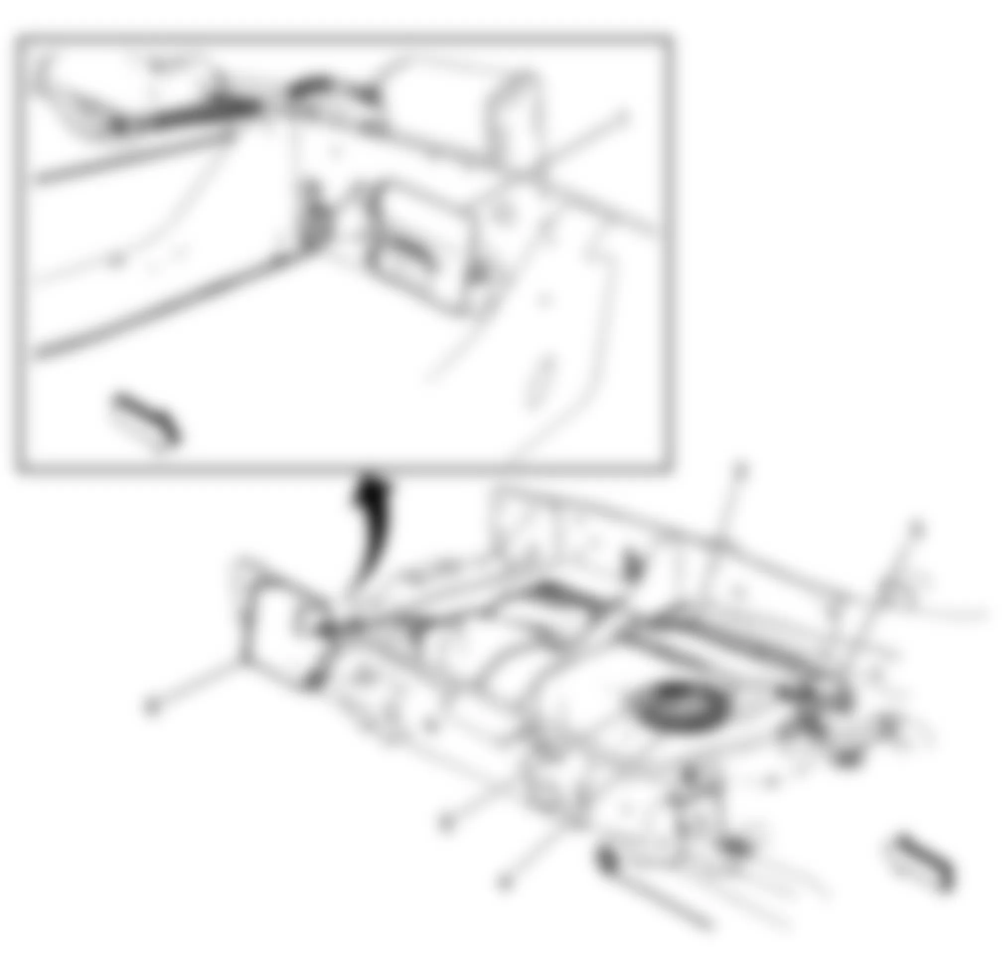
Fig. 57: Hummer H2 2009 - Component Locations - Rear Seat Components
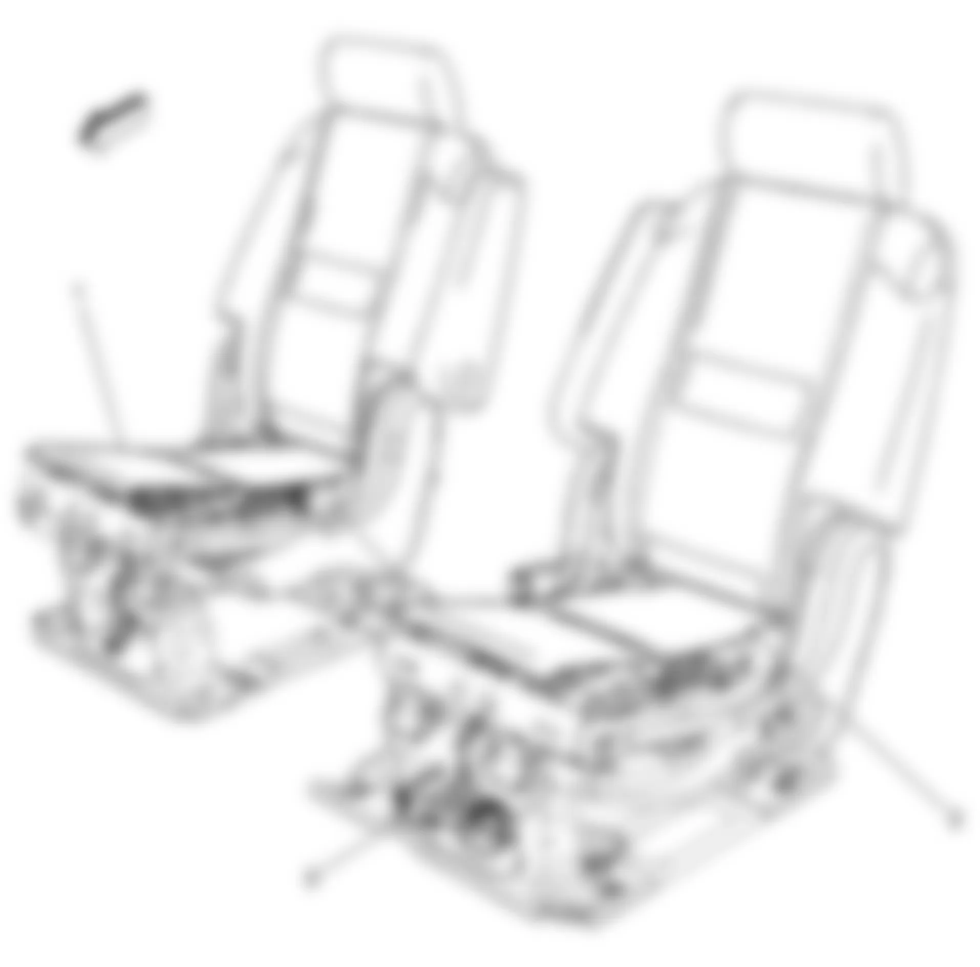
Fig. 58: Hummer H2 2009 - Component Locations - Driver Seat Components
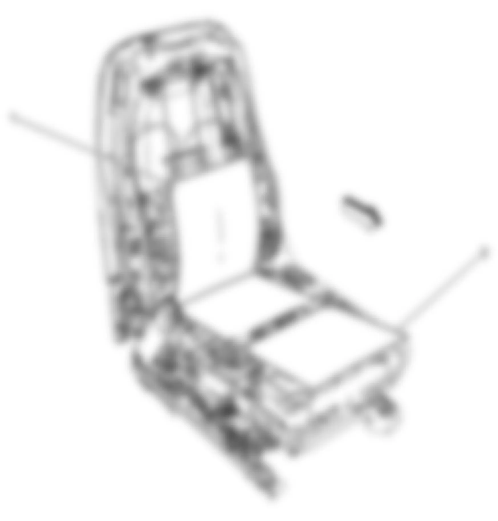
Fig. 59: Hummer H2 2009 - Component Locations - Passenger Seat Components
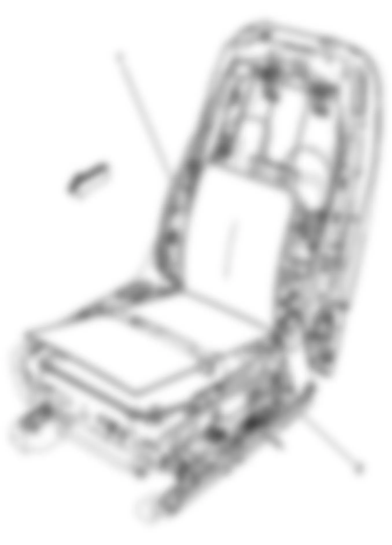
Fig. 60: Hummer H2 2009 - Component Locations - Steering Column Components
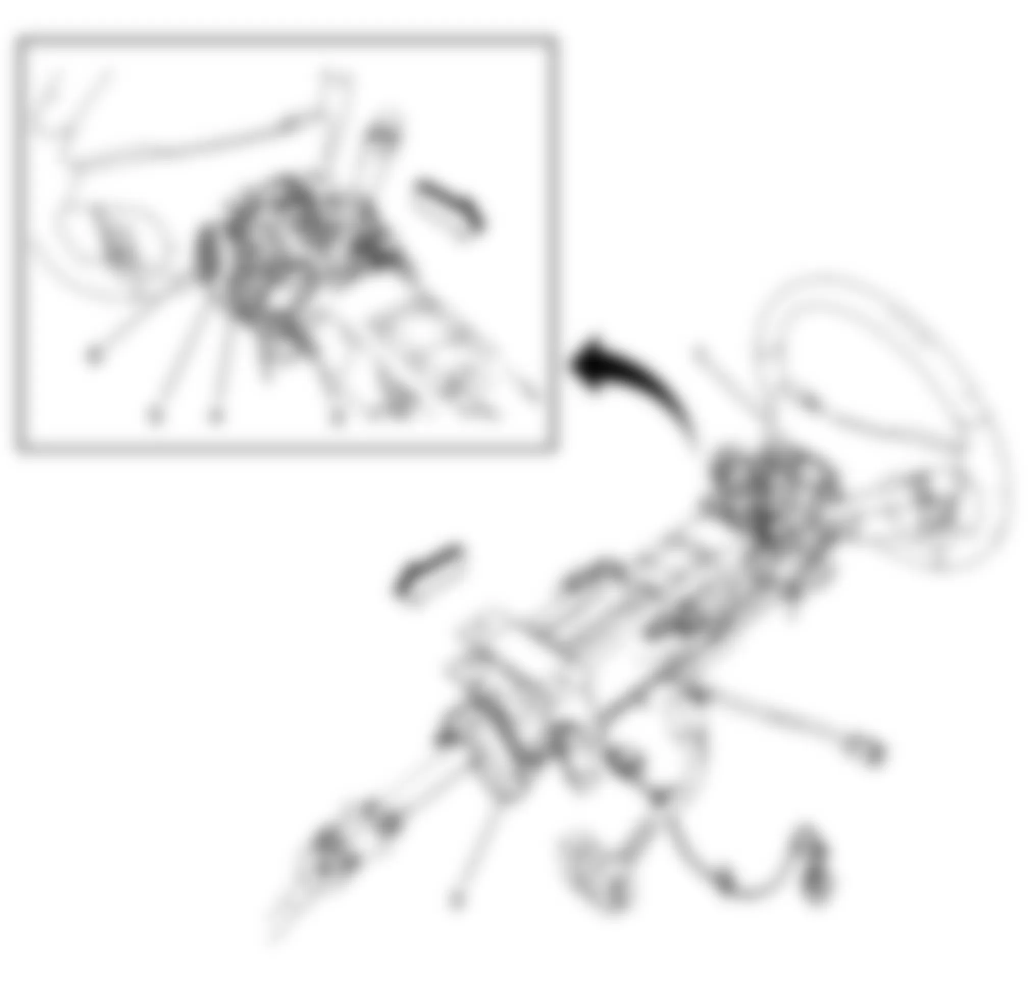
Fig. 61: Hummer H2 2009 - Component Locations - Front Left Side Of Passenger Compartment
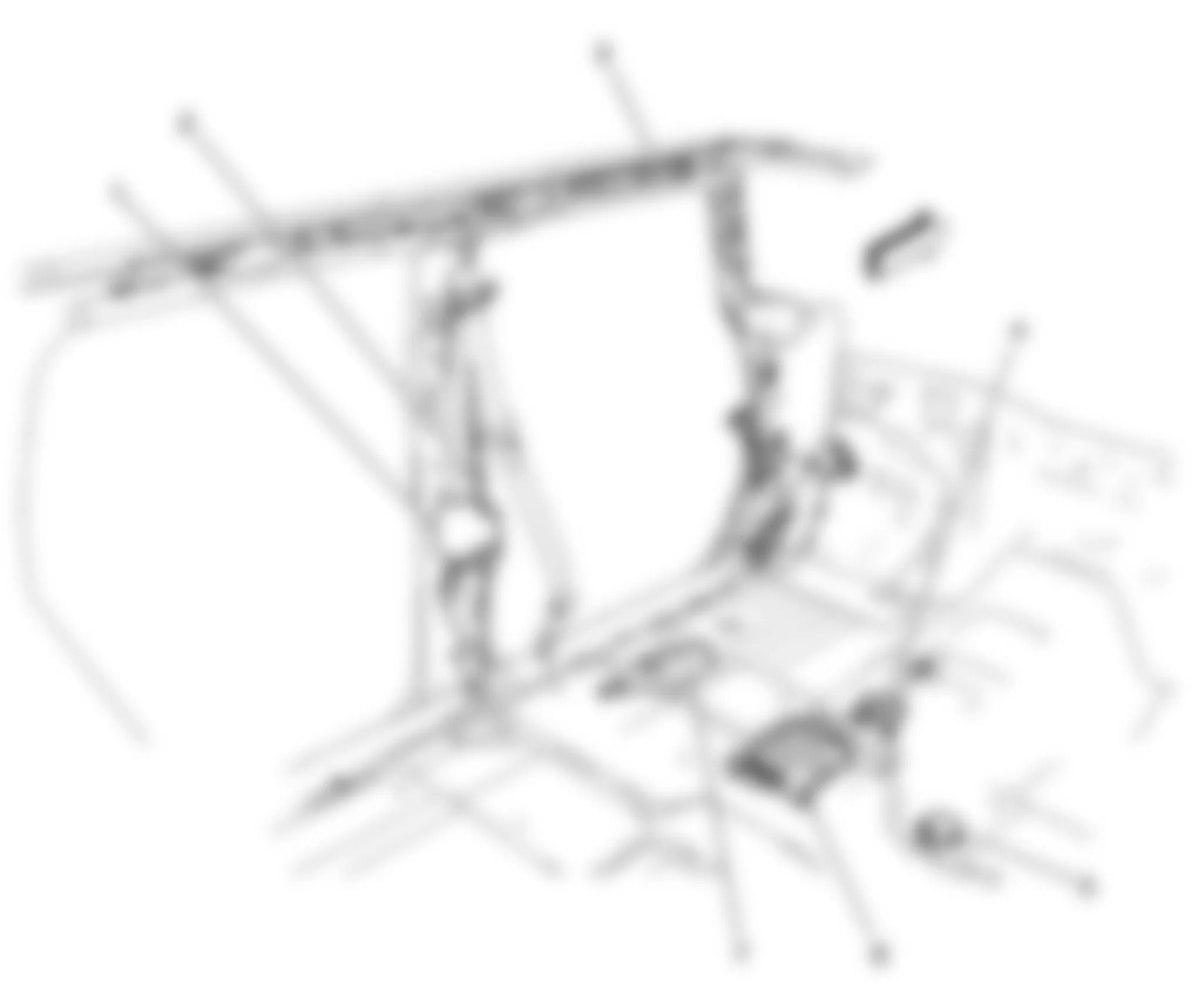
Fig. 62: Hummer H2 2009 - Component Locations - Right Front Passenger Compartment
Fig. 63: Hummer H2 2009 - Component Locations - Front Doors
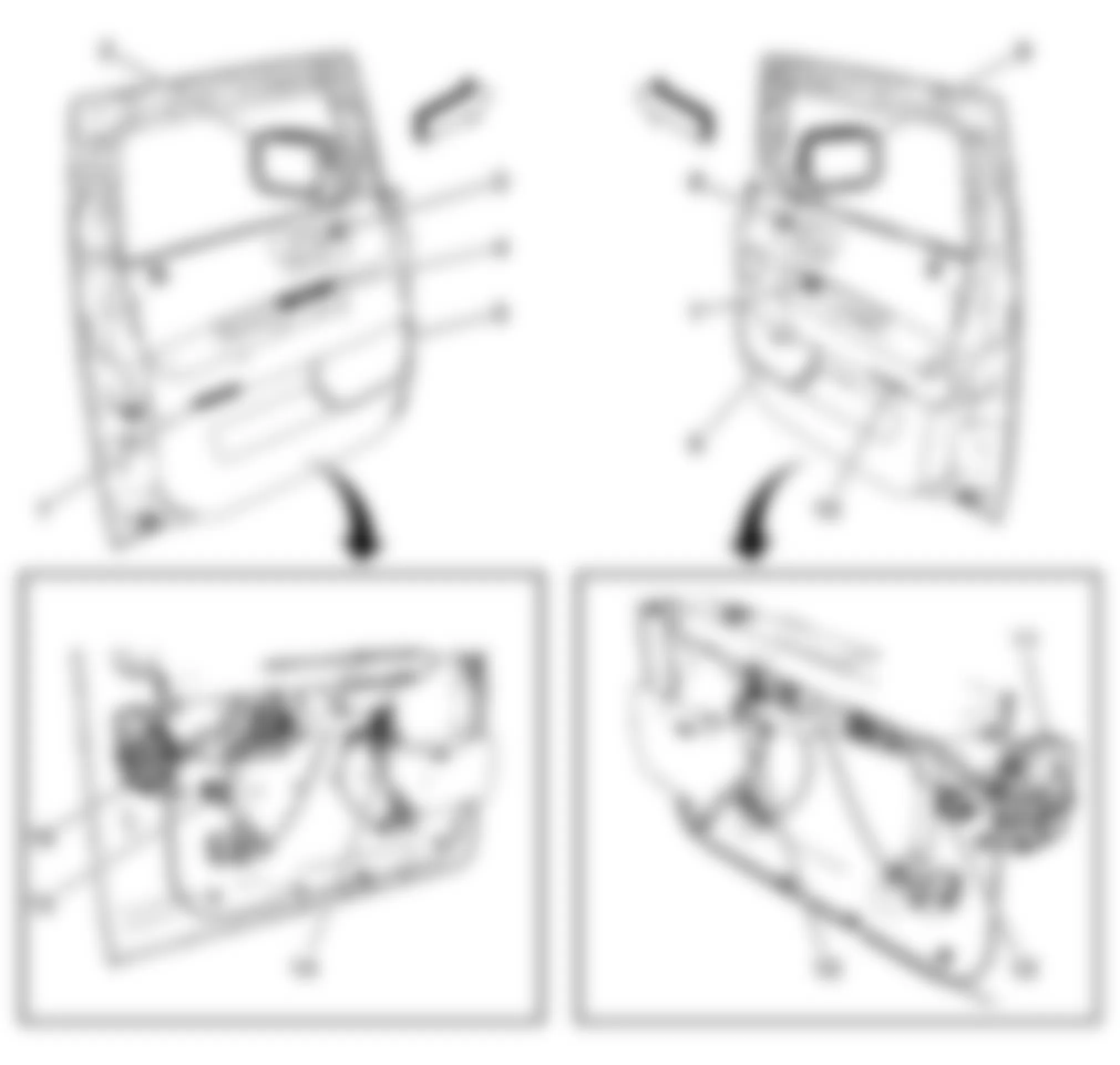
Fig. 64: Hummer H2 2009 - Component Locations - Rear Passenger Doors
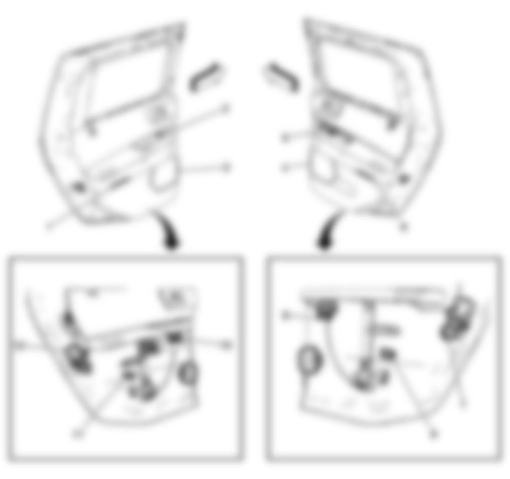
Fig. 65: Hummer H2 2009 - Component Locations - Midgate Components
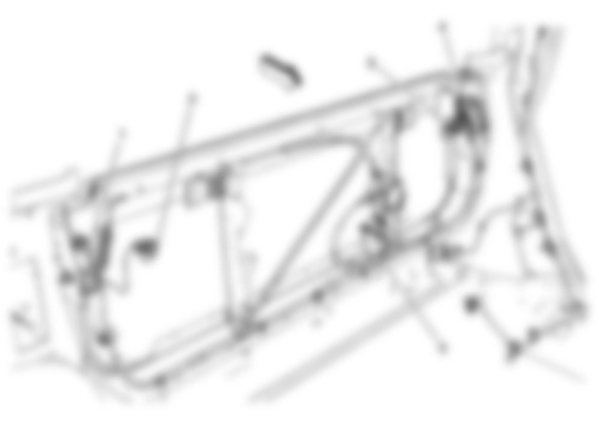
Fig. 66: Hummer H2 2009 - Component Locations - Rear Exterior
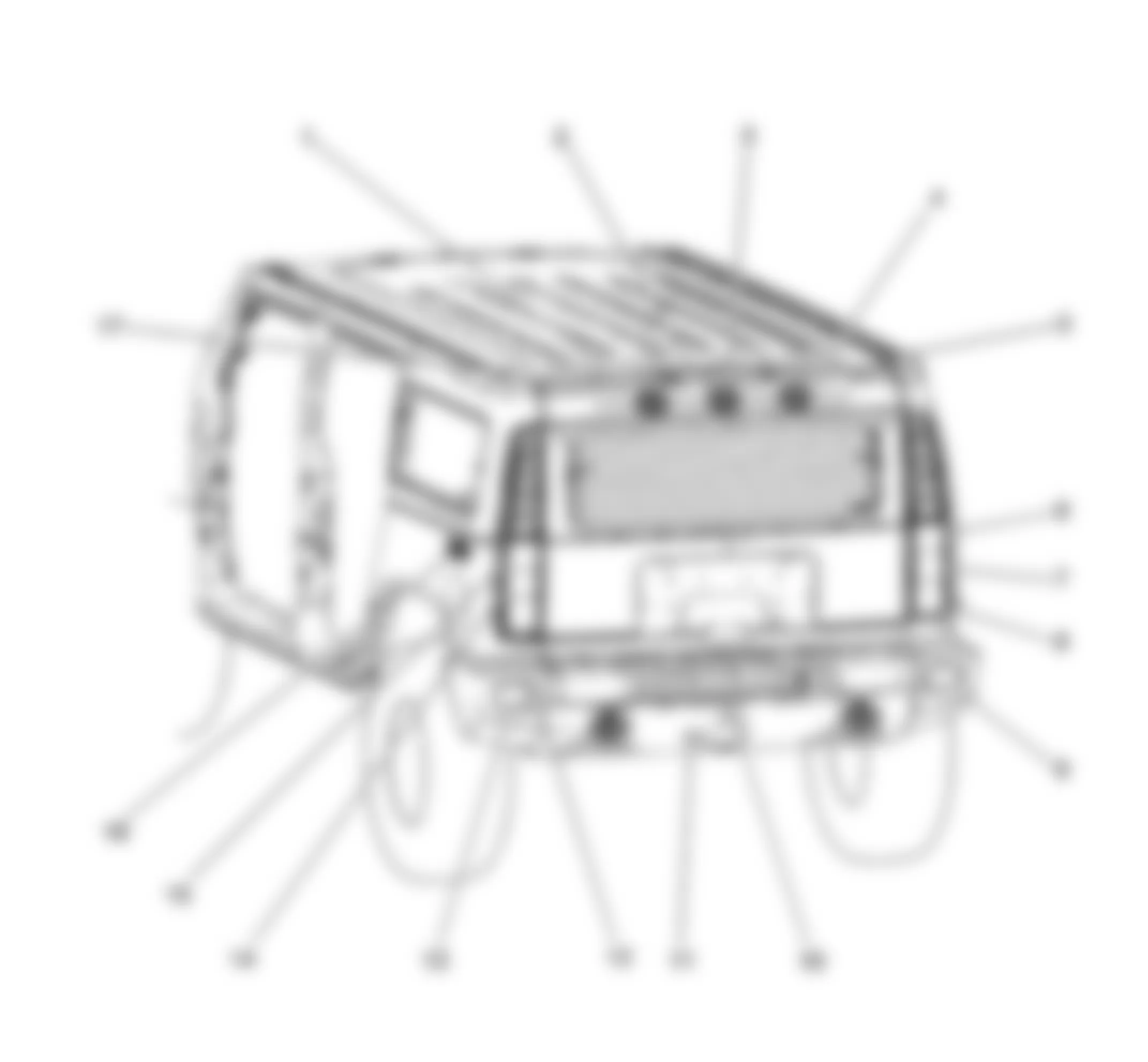
Fig. 67: Hummer H2 2009 - Component Locations - Drivers Seat Components
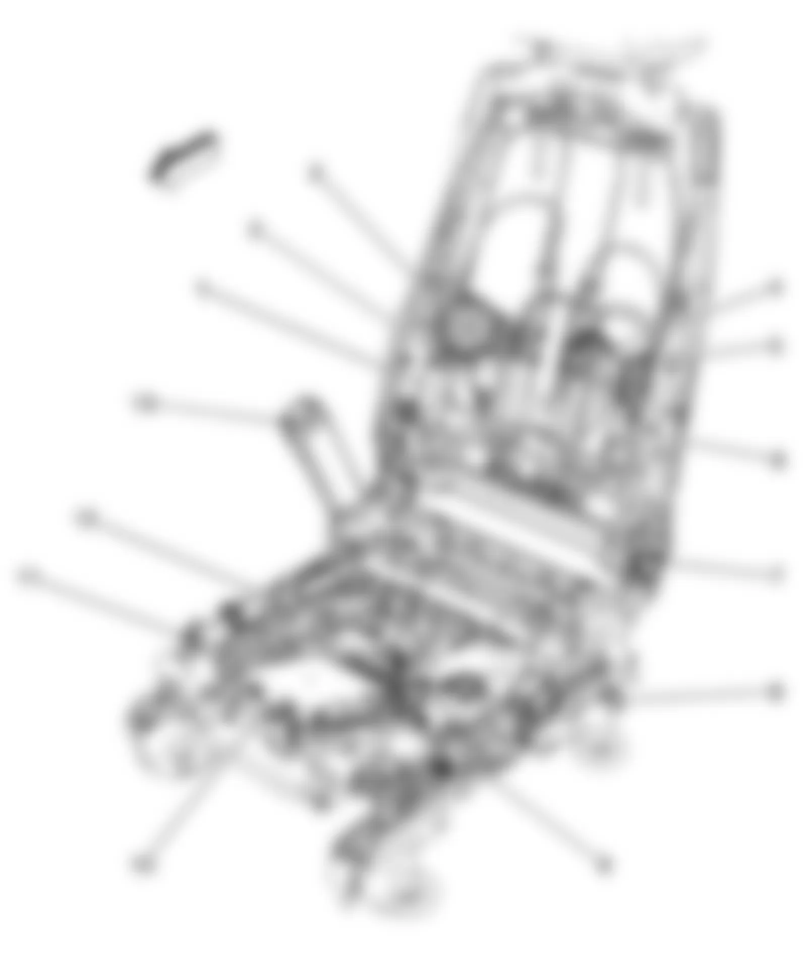
Fig. 68: Hummer H2 2009 - Component Locations - Passenger Seat Components
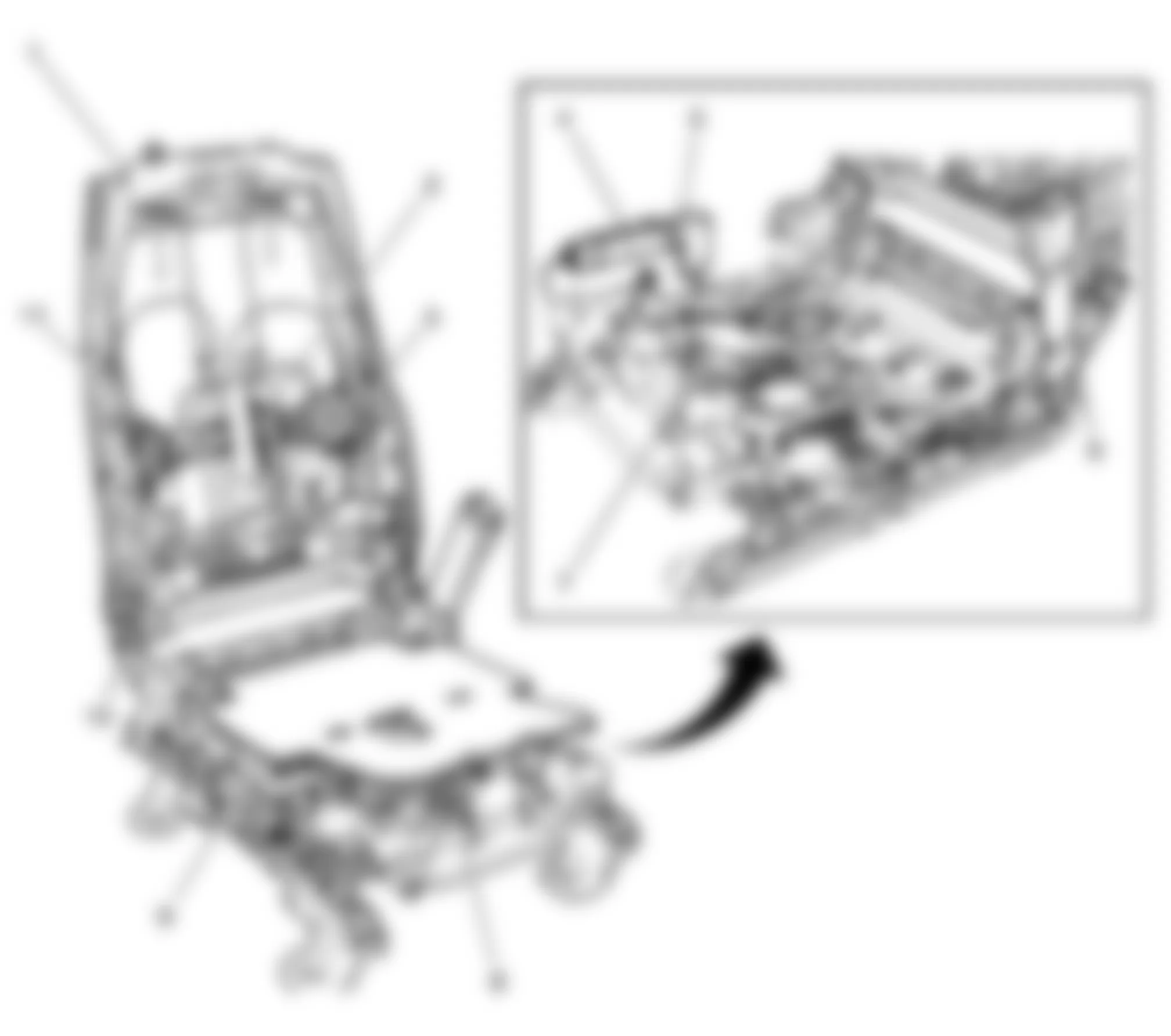
Fig. 69: Hummer H2 2009 - Component Locations - Forward Lamp
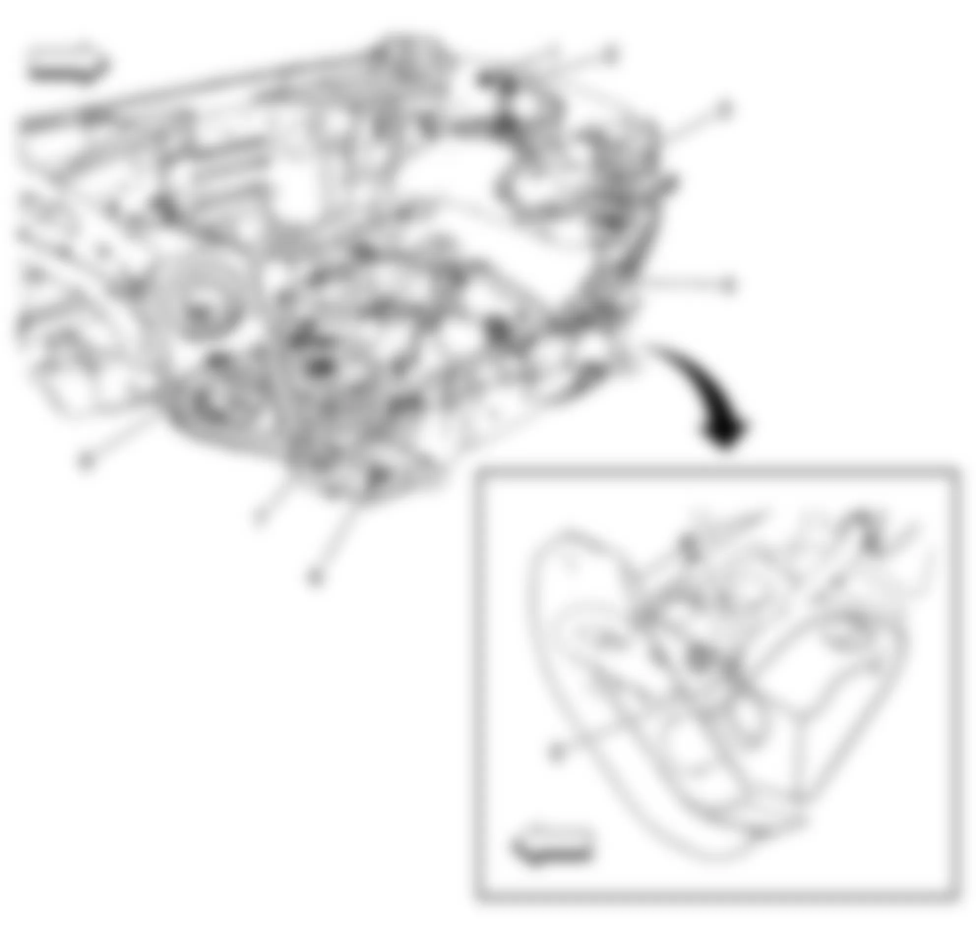
Fig. 70: Hummer H2 2009 - Component Locations - Rear Of Engine Compartment
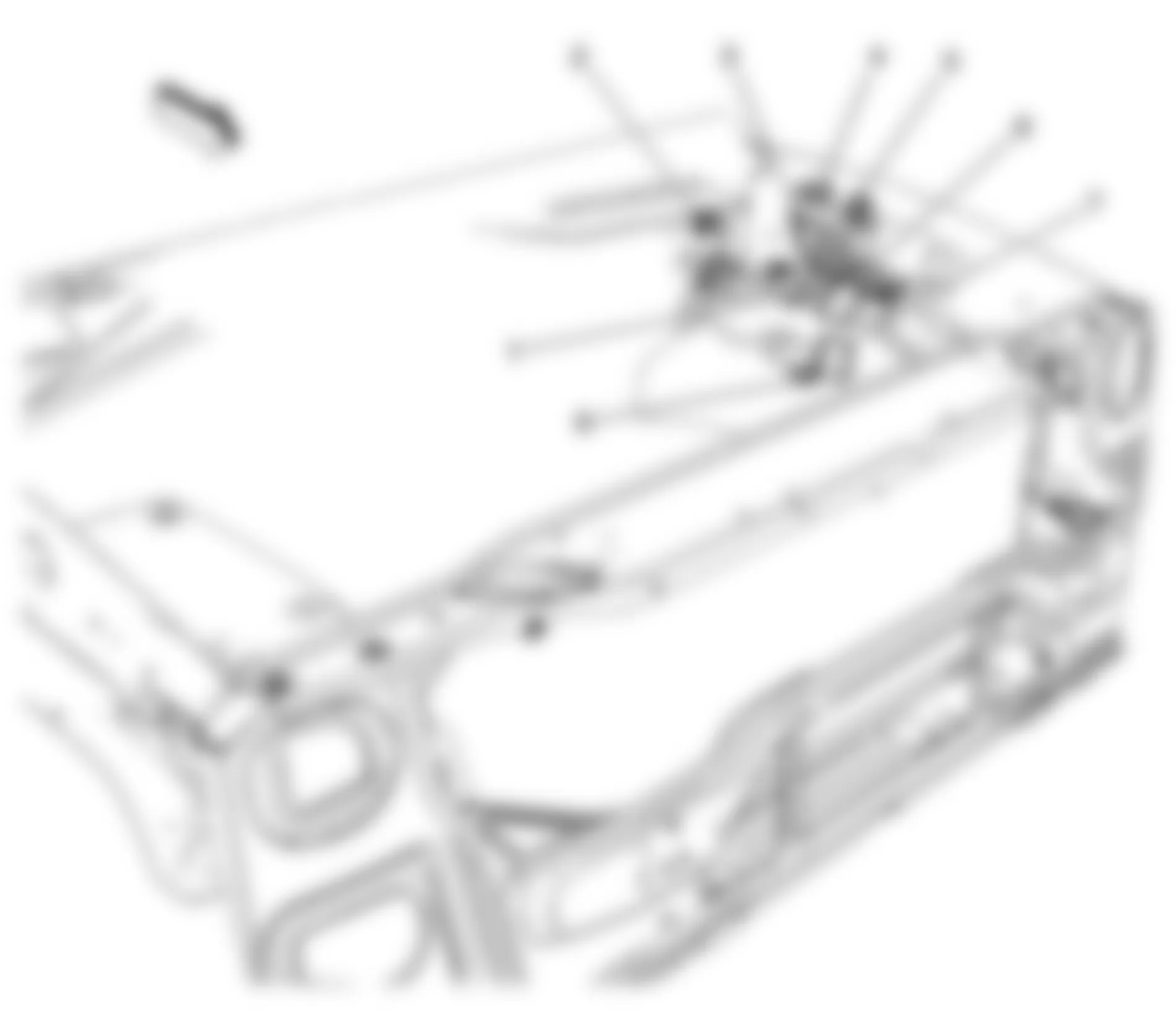
Fig. 71: Hummer H2 2009 - Component Locations - Engine Front
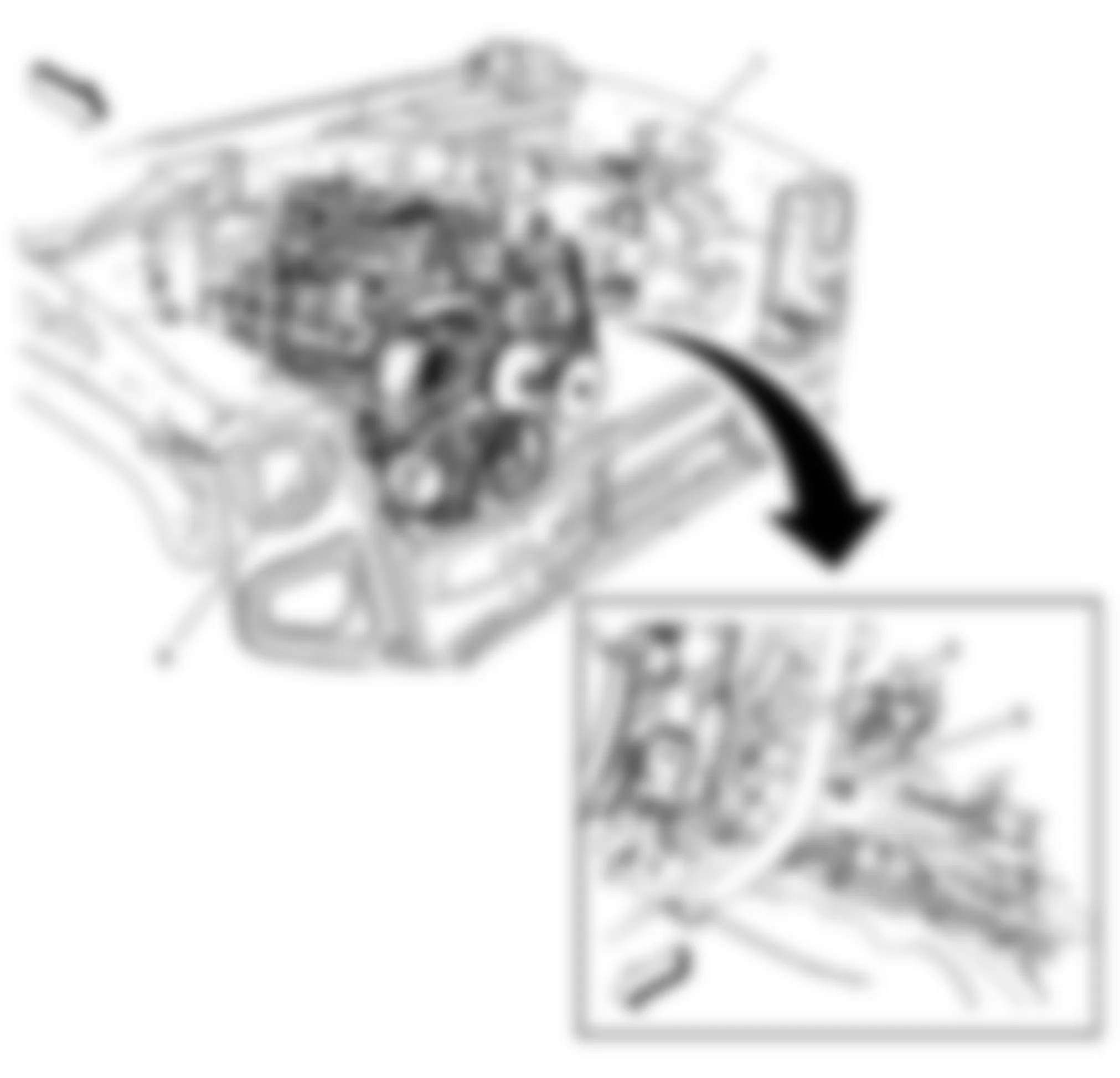
Fig. 72: Hummer H2 2009 - Component Locations - Left Rear Of Engine
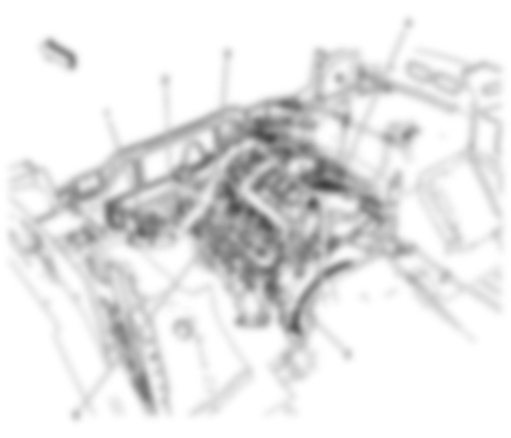
Fig. 73: Hummer H2 2009 - Component Locations - Left Front Passenger Compartment
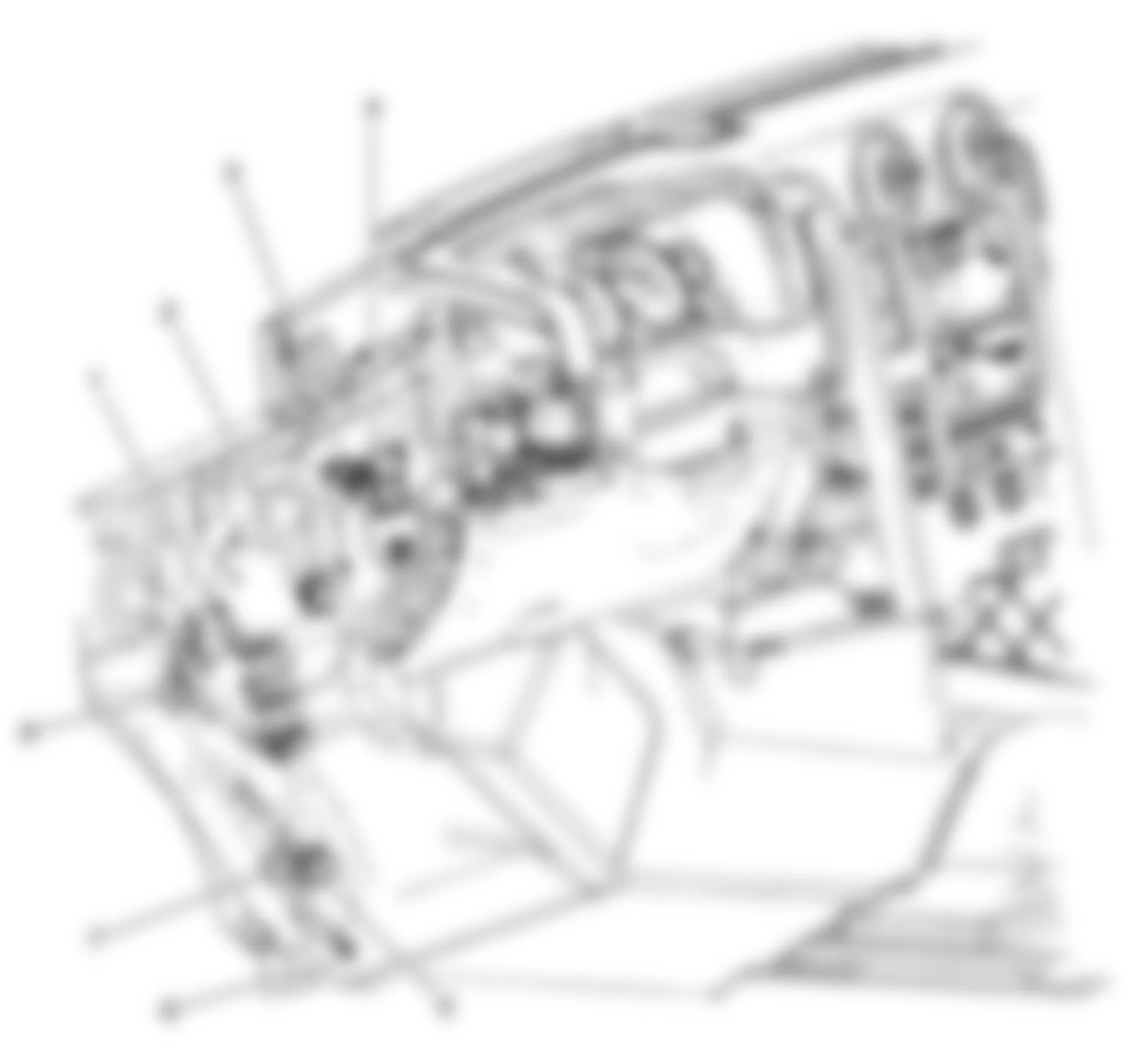
Fig. 74: Hummer H2 2009 - Component Locations - Right Front Passenger Compartment
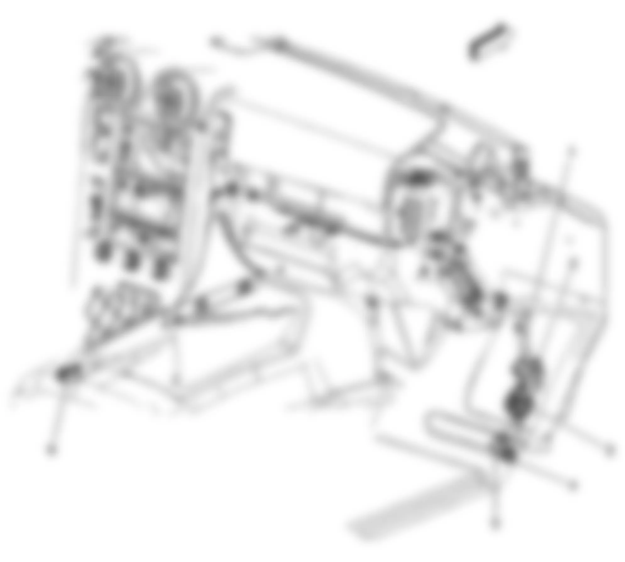
Fig. 75: Hummer H2 2009 - Component Locations - Cargo Box Harness
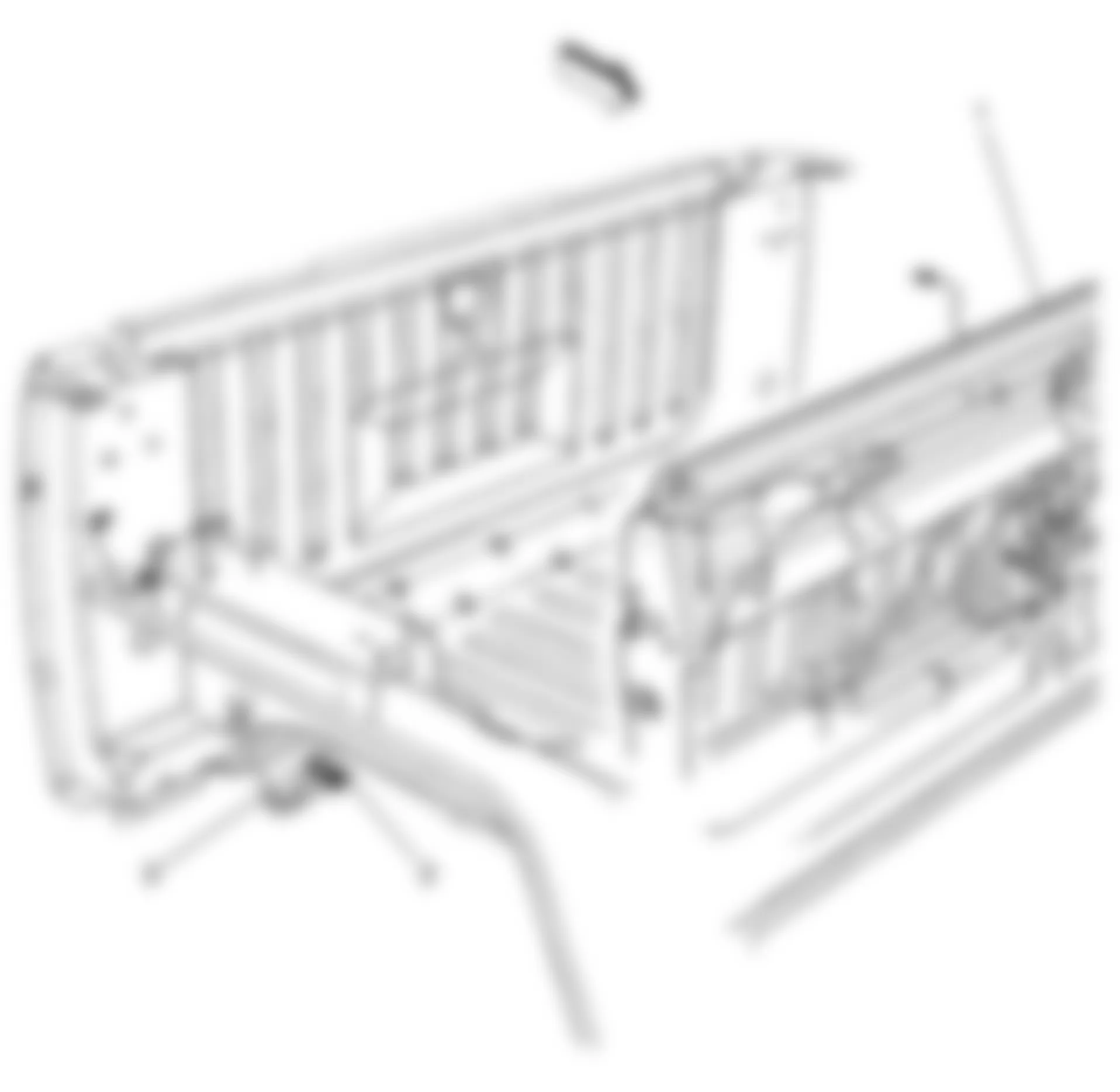
Fig. 76: Hummer H2 2009 - Component Locations - Midgate Harness
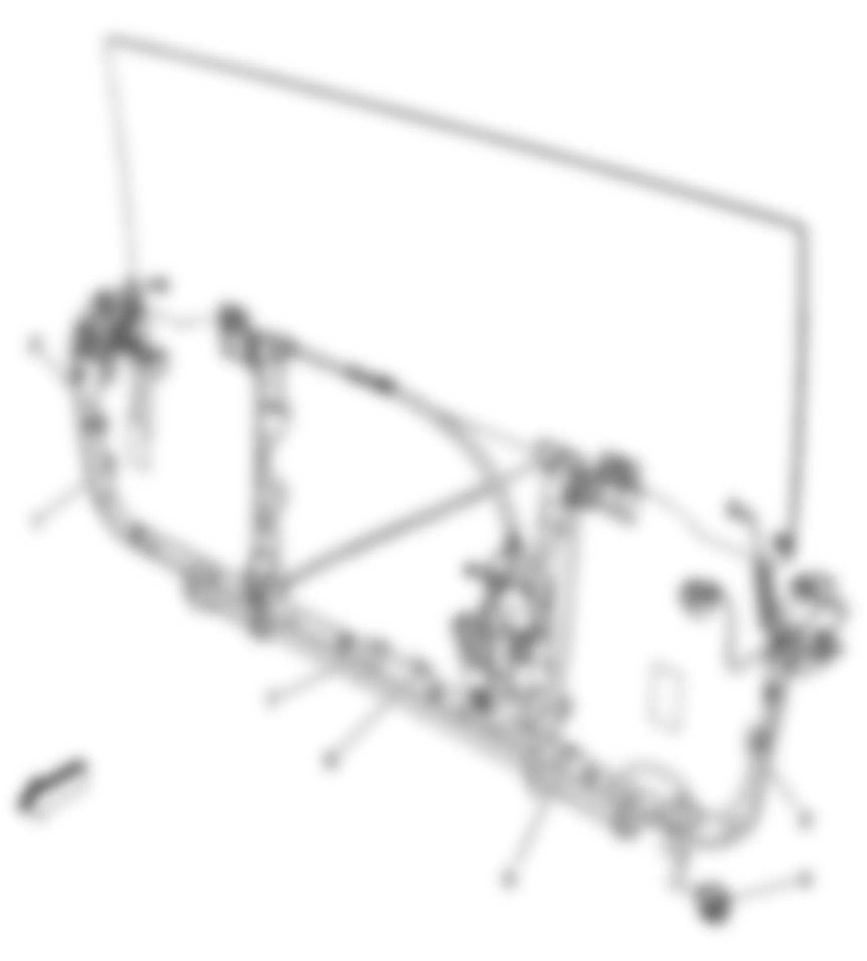
Fig. 77: Hummer H2 2009 - Component Locations - Left Passenger Compartment
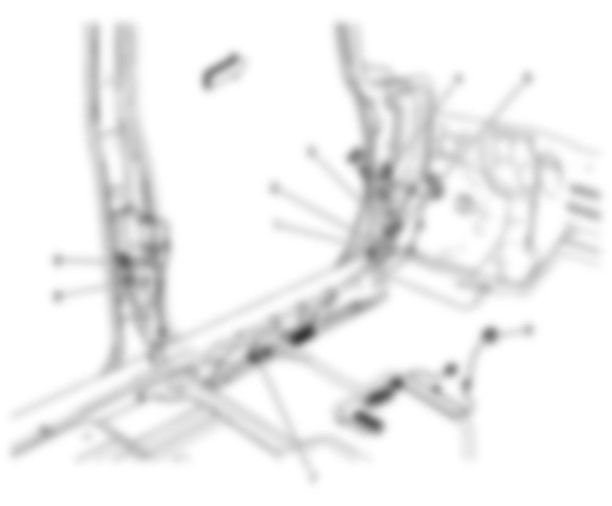
Fig. 78: Hummer H2 2009 - Component Locations - Front Dome Lamp Harness
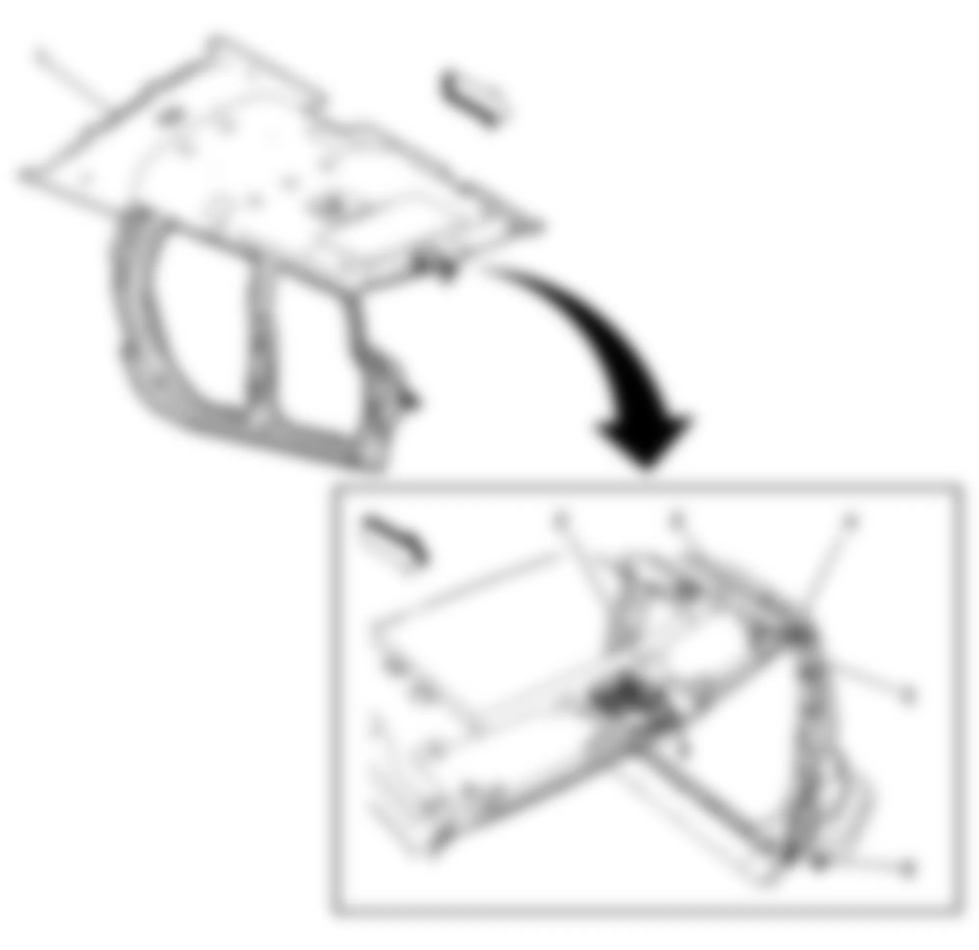
Fig. 79: Hummer H2 2009 - Component Locations - Right Rear Passenger Compartment
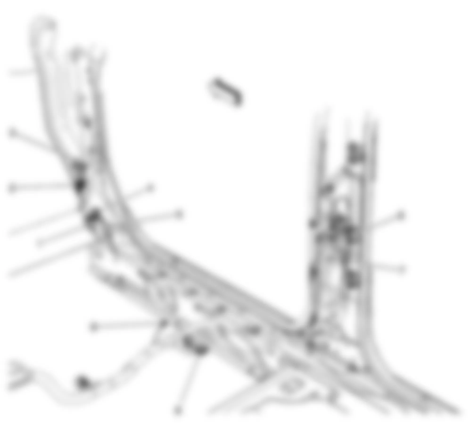
Fig. 80: Hummer H2 2009 - Component Locations - Right Rear Cargo Area
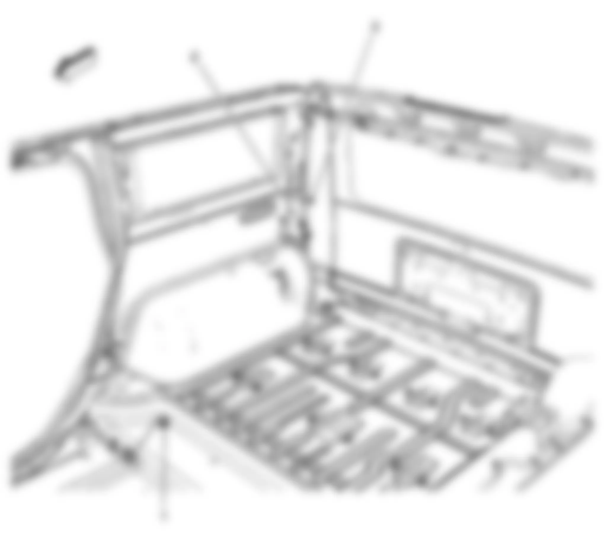
Fig. 81: Hummer H2 2009 - Component Locations - Left Rear Passenger Compartment (SUT)
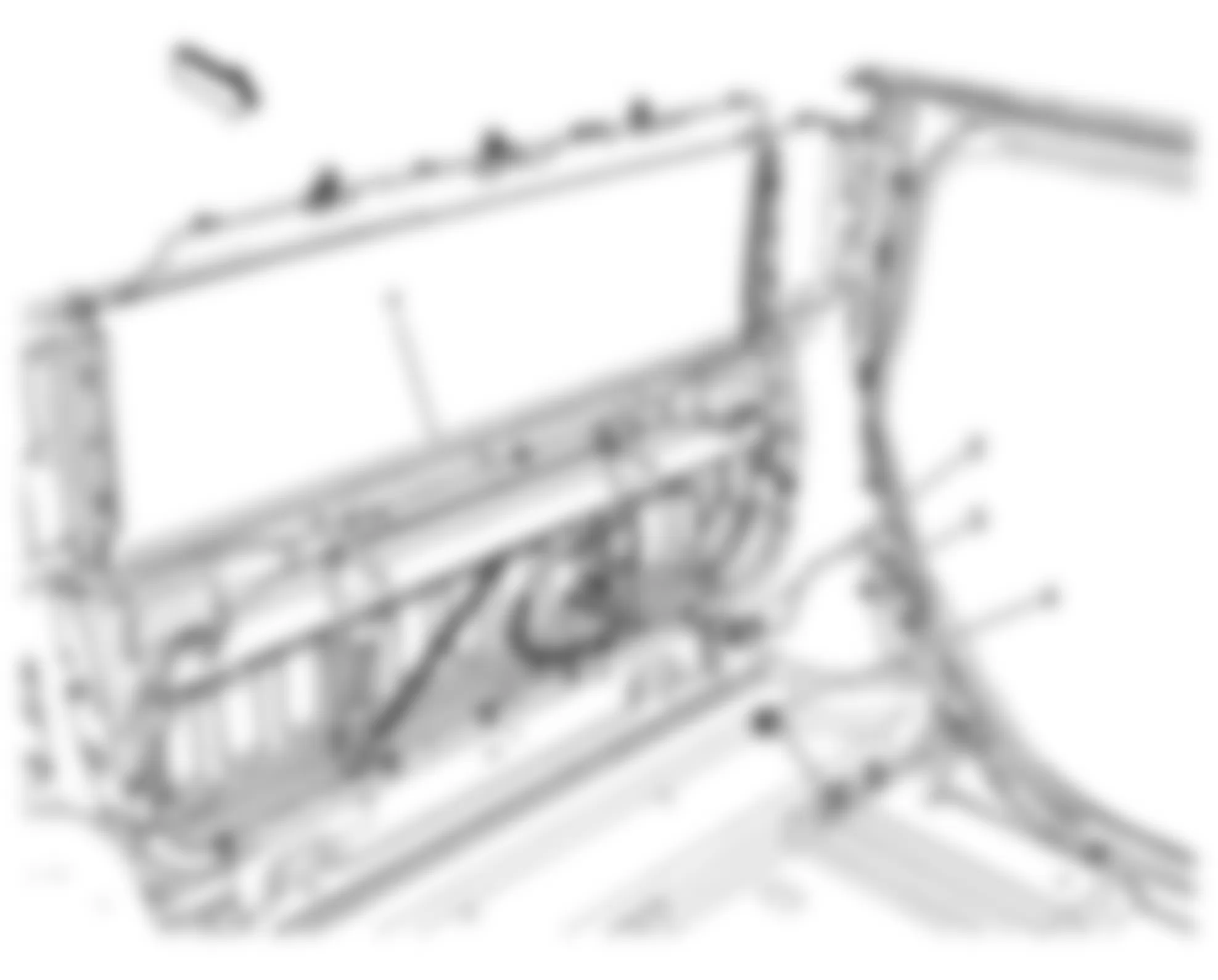
Fig. 82: Hummer H2 2009 - Component Locations - Rear Frame
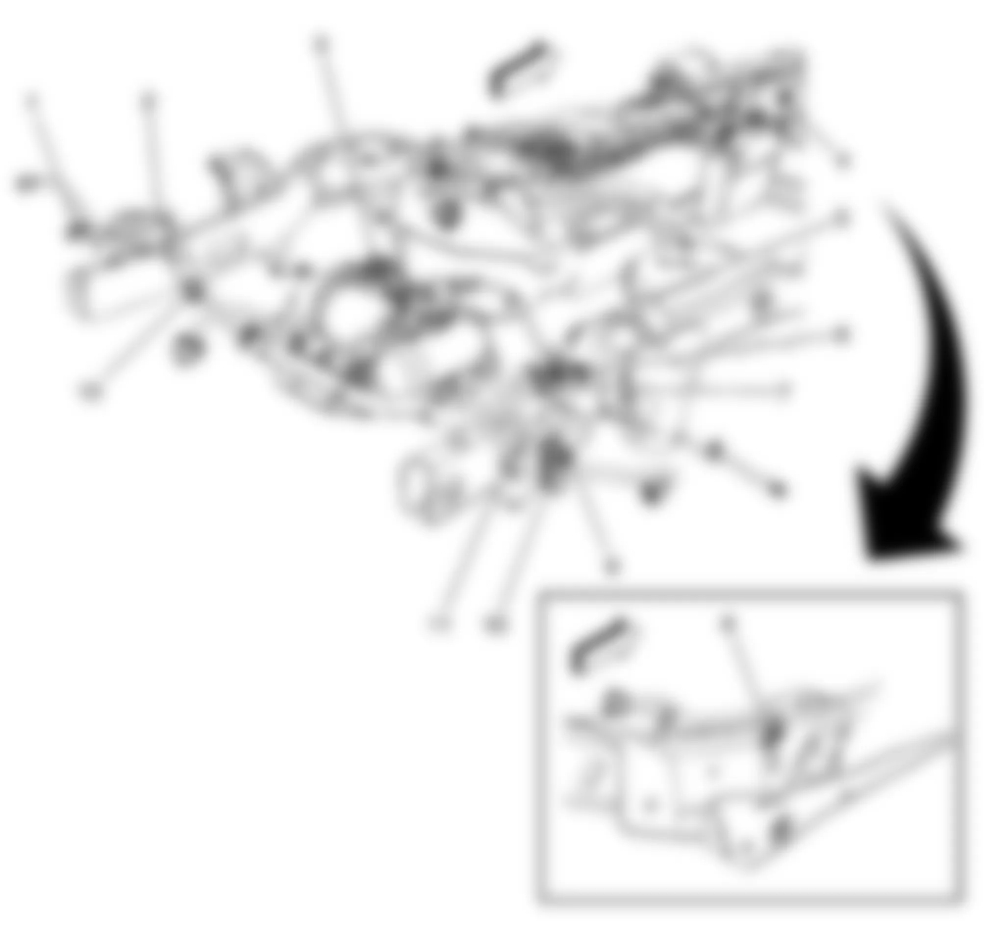
Fig. 83: Hummer H2 2009 - Component Locations - Left Rear Cargo Area (SUV)
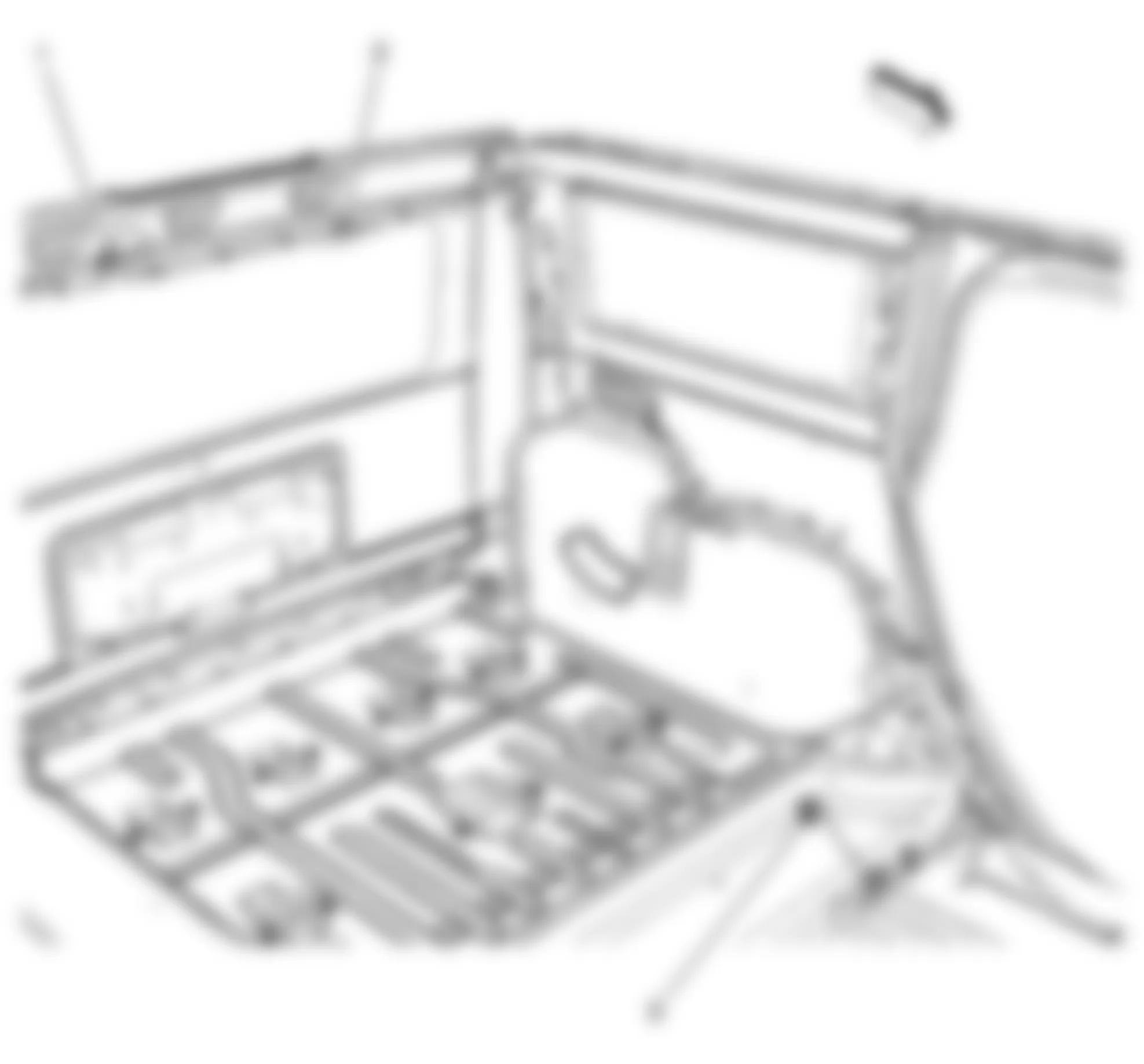
Fig. 84: Hummer H2 2009 - Component Locations - Front Doors
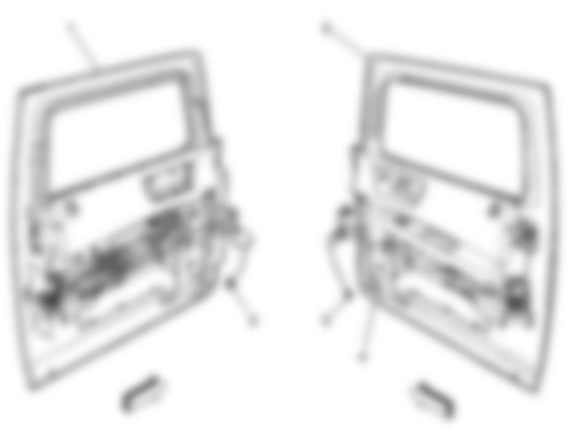
Fig. 85: Hummer H2 2009 - Component Locations - Rear Doors
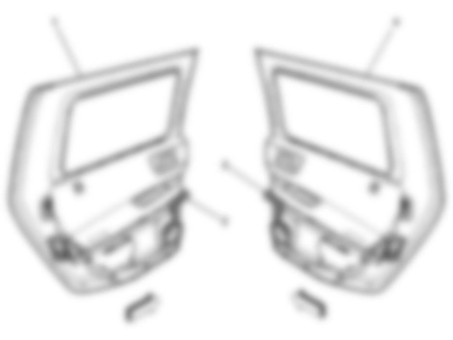
Fig. 86: Hummer H2 2009 - Component Locations - Chassis Harness - Splices
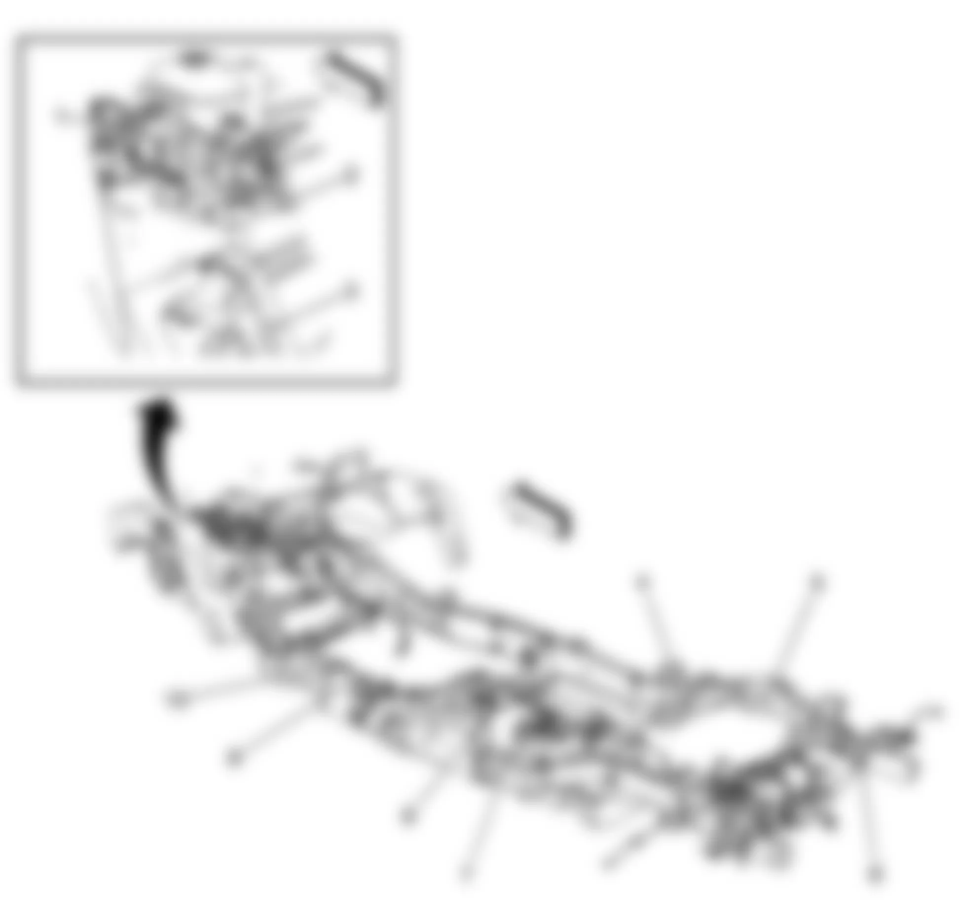
Fig. 87: Hummer H2 2009 - Component Locations - Body Harness - Splices
Fig. 88: Hummer H2 2009 - Component Locations - Floor Console
Fig. 89: Hummer H2 2009 - Component Locations - Under Dash
Fig. 90: Hummer H2 2009 - Component Locations - Instrument Panel Splices
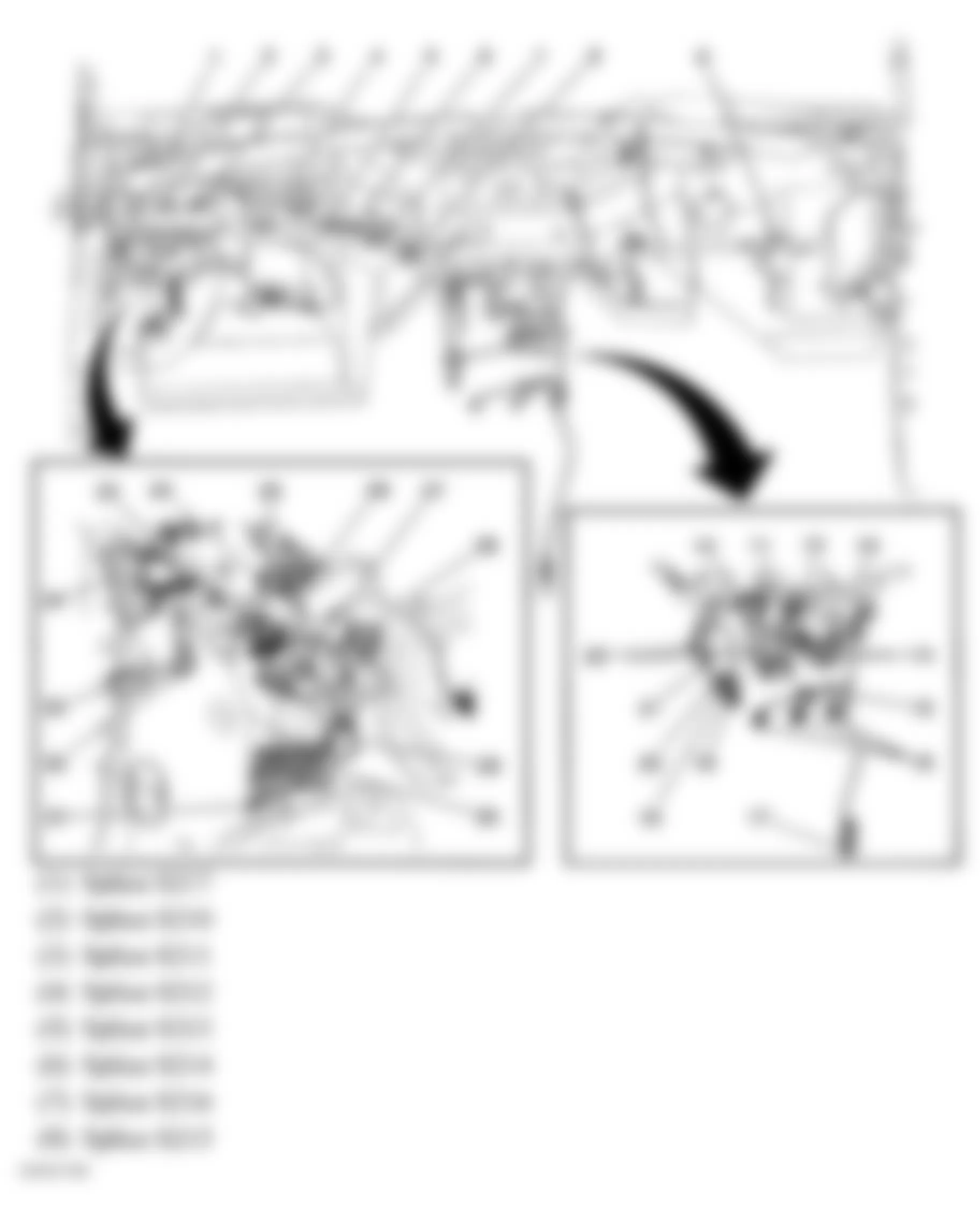
Fig. 91: Hummer H2 2009 - Component Locations - Headliner
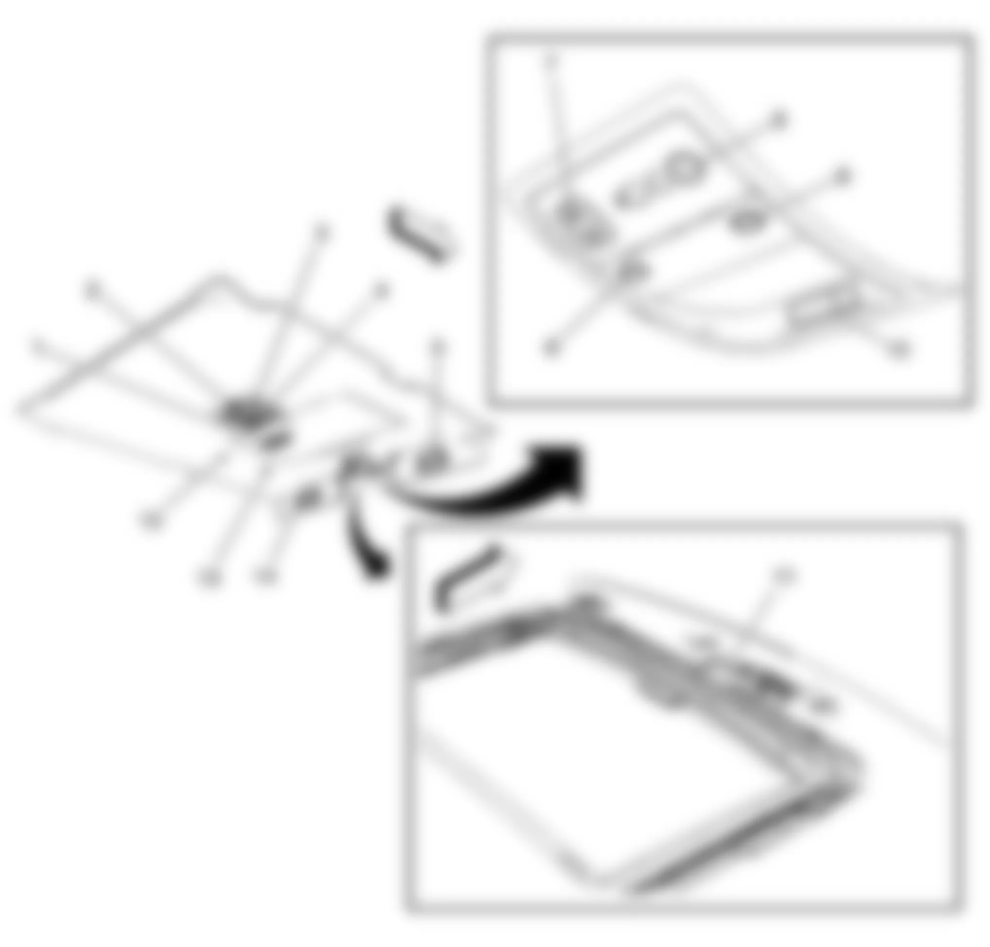
Fig. 92: Hummer H2 2009 - Component Locations - Ground Location (G300)
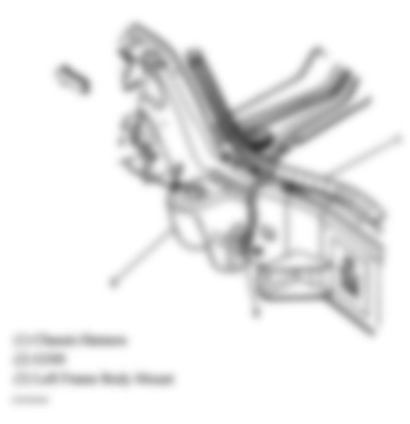
Fig. 93: Hummer H2 2009 - Component Locations - Antenna Locations
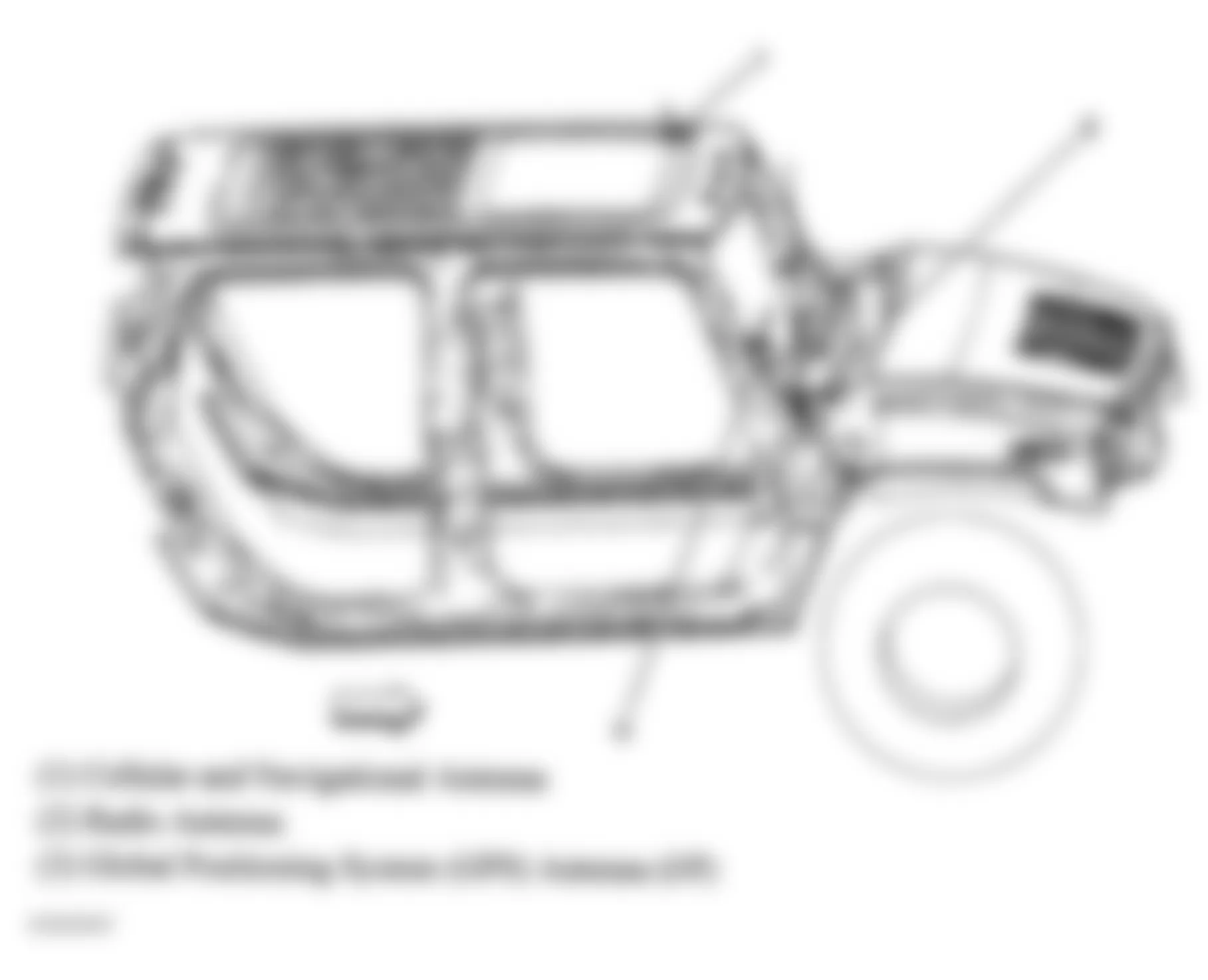
Fig. 94: Hummer H2 2009 - Component Locations - Under Hood Fuse Block
Fig. 95: Hummer H2 2009 - Component Locations - Front Door
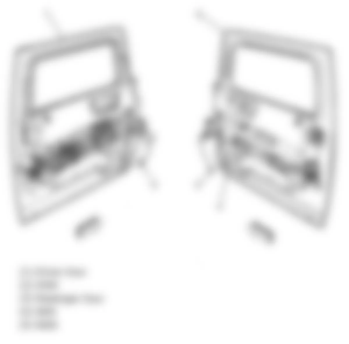
Fig. 96: Hummer H2 2009 - Component Locations - Right Side Of Dash
Fig. 97: Hummer H2 2009 - Component Locations - Dash Panel Harness
Fig. 98: Hummer H2 2009 - Component Locations - Fuel System Components
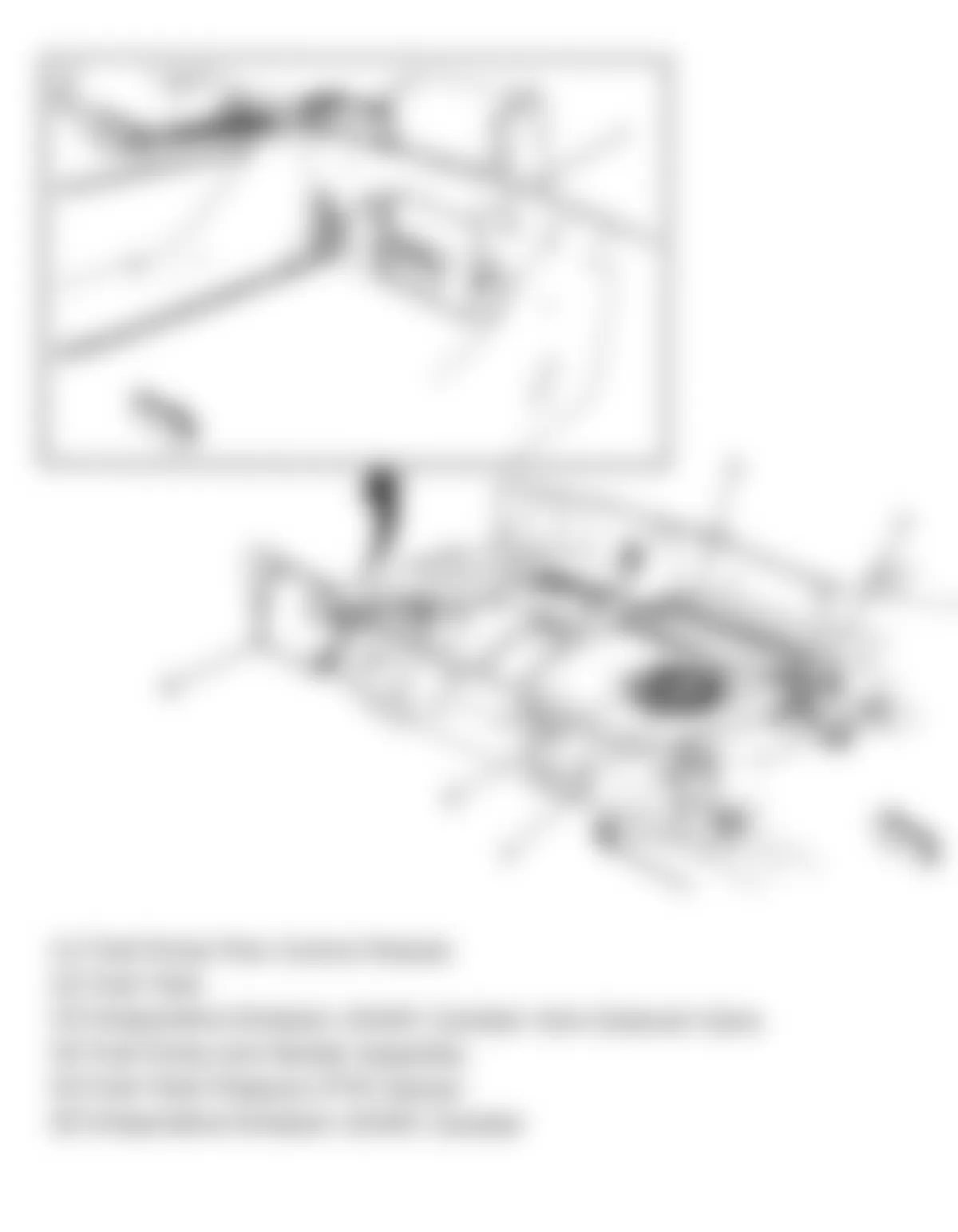
Fig. 99: Hummer H2 2009 - Component Locations - Rear Compartment Components