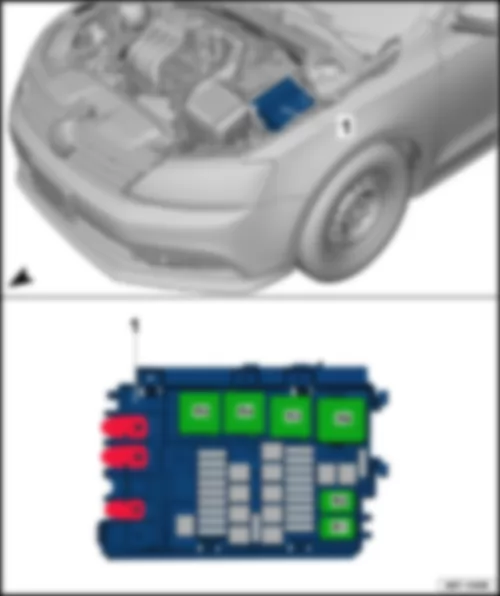
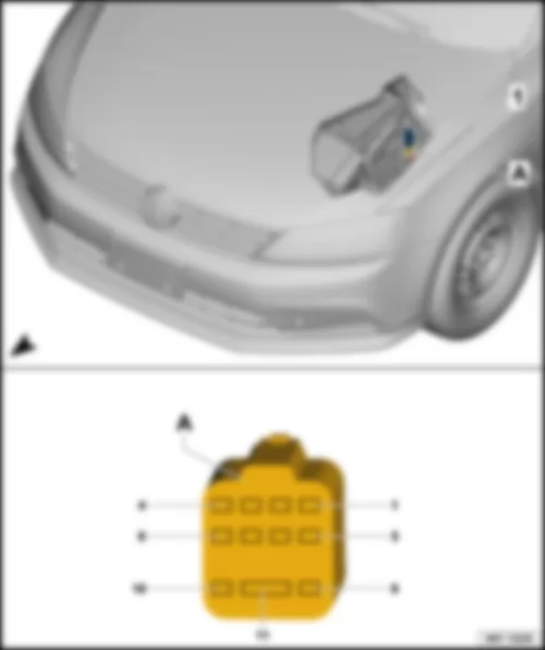
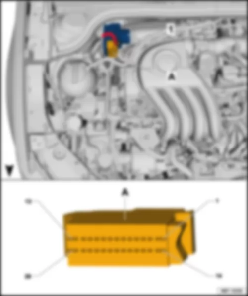
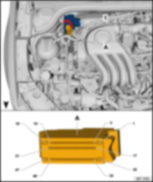
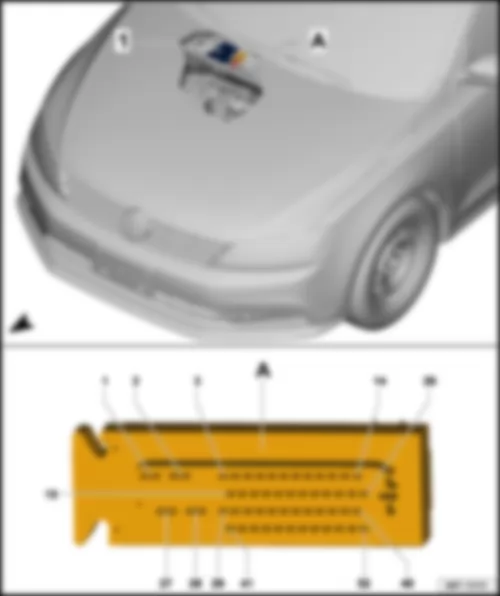
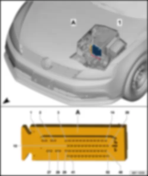
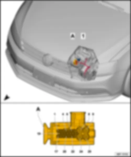
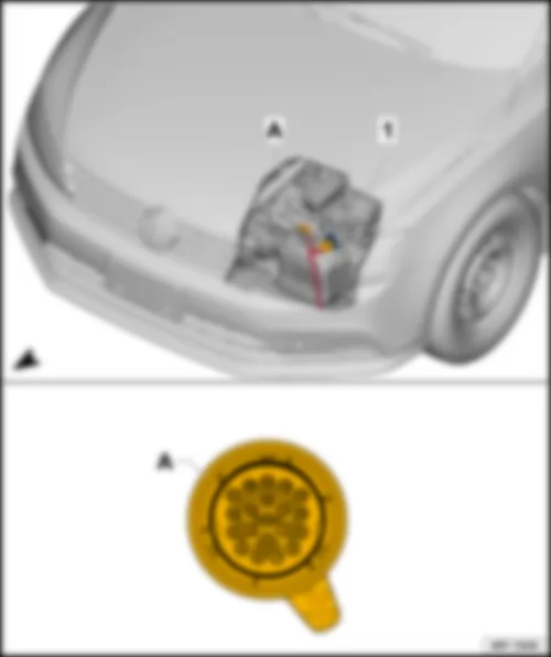
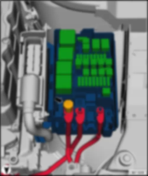
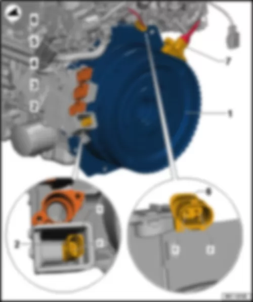
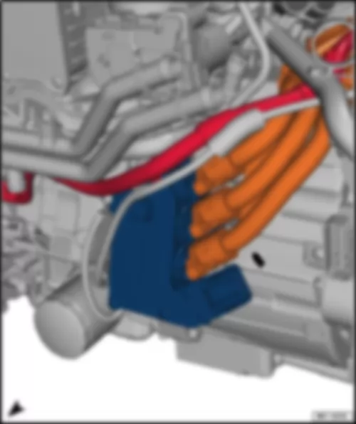
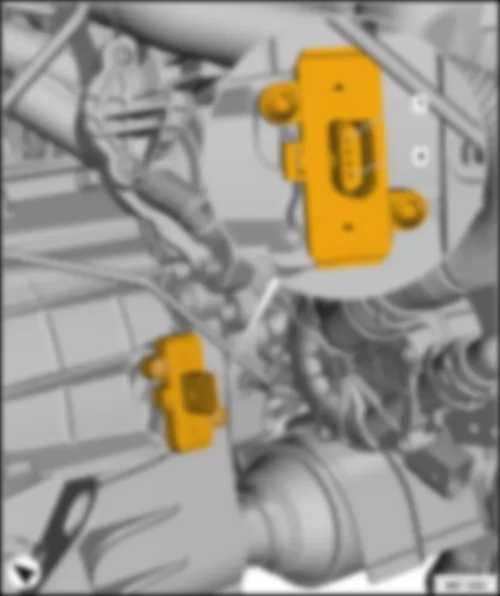
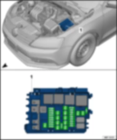
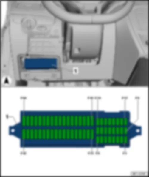
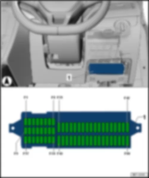
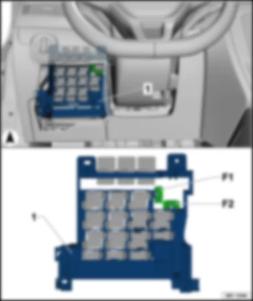
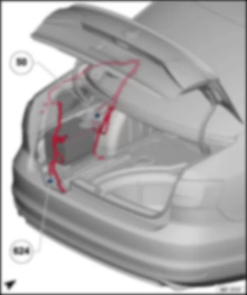
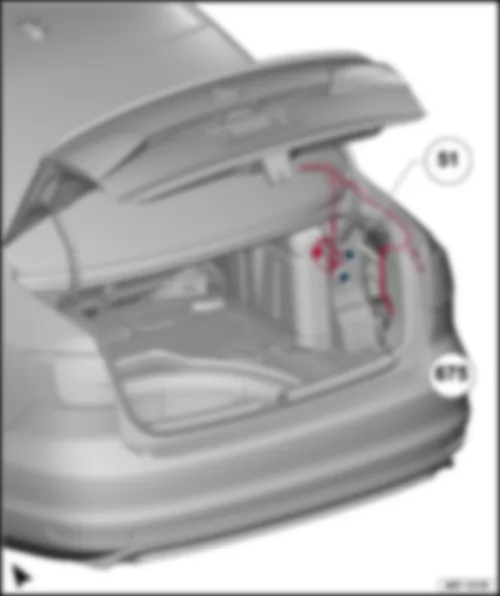
| Slot | Current flow diagram designation | Nominal value | Function/component | Terminal |
| F1 | Not assigned | - | | - |
| F2 | Fuse 2 on fuse holder B -SB2- | 20 A | Engine control unit -J623- | 87 |
| F3 | Fuse 3 on fuse holder B -SB3- | 5 A | High heat output relay -J360- | 87 |
| | | | Low heat output relay -J359- | |
| | | | Radiator fan control unit -J293- | |
| F4 | Fuse 4 on fuse holder B -SB4- | 10 A3)
15 A6) | Lambda probe heater -Z19- | 87 |
| | | | Lambda probe 1 heater after catalytic converter -Z29- | |
| | | | Coolant pump for high-temperature circuit -V467-3) | |
| | | | Low-temperature circuit coolant pump -V468- | |
| | | | Lambda probe heater 2 -Z28- | |
| F5 | Fuse 5 on fuse holder B -SB5-7) | 15 A | Secondary air inlet valve -N112- | 87 |
| F6 | Fuse 6 on fuse holder B -SB6- | 10 A | Fuel system diagnostic pump -V144-
Fuel tank shut-off valve -N288-
Secondary air pump relay -J299-1)
Heater element for crankcase breather -N79-
Lambda probe heater 2 -Z28- | 87 |
| F7 | Fuse 7 on fuse holder B -SB7- | 20 A
30 A5),7) 10 A2),3) | Ignition coil 1 with output stage -N70-
Ignition coil 2 with output stage -N127-
Ignition coil 3 with output stage -N291-
Ignition coil 4 with output stage -N292-
Ignition coil 5 with output stage -N323-5)
Ignition transformer -N152-
Fuel pressure regulating valve -N276-2)4)
Fuel metering valve -N290-2)4)
Camshaft control valve 1 -N205-2) | 87 |
| F8 | Fuse 8 on fuse holder B -SB8- | 10 A | Throttle valve module -J338-
Charge pressure control solenoid valve -N75-
Secondary air inlet valve -N112-
Secondary air pump relay -J299-
Activated charcoal filter solenoid valve 1 -N80-
Camshaft control valve 1 -N205-
Turbocharger air recirculation valve -N249-
Intake manifold flap valve -N316-
Exhaust camshaft control valve 1 -N318-3)
Charge pressure control solenoid valve -N75-4)
Exhaust gas recirculation cooler changeover valve -N345-4)
Heater element for crankcase breather -N79-4)
Valve for oil pressure control -N428-3)
Pressure regulator for disengagement clutch -N511-3)
Radiator blind control motor -V544- | 87 |
| F9 | Fuse 9 on fuse holder B -SB9- | 10 A
15 A3),7) | Fuel pump relay -J17-
Valve for oil pressure control -N428-
Turbocharger air recirculation valve -N249-
Intake manifold flap valve -N316-
Automatic glow period control unit -J179-4)
Circulation pump -V55-4)
Electric fuel pump 2 relay -J49-4) | 87 |
| F10 | Fuse 10 on fuse holder B -SB10- | 5 A | Brake light switch -F-
Clutch position sender -G476- | 87 |
| F11 | Not assigned | - | | - |
| F12 | Fuse 12 on fuse holder B -SB12- | 30 A | Ignition coil 1 with output stage -N70-
Ignition coil 2 with output stage -N127-
Ignition coil 3 with output stage -N291-
Ignition coil 4 with output stage -N292-
Coolant circulation pump -V50- | 87 |
| F13 | Fuse 13 on fuse holder B -SB13- | 30 A | Voltage stabiliser -J532-
Control unit with display for radio and navigation -J503-
Radio -R- | 30 |
| F14 | Fuse 14 on fuse holder B -SB14- | 10 A | Engine control unit -J623-
Main relay -J271-4) | 30 |
| F15 | Fuse 15 on fuse holder B -SB15- | 30 A | ABS control unit -J104- | 30 |
| F16 | Fuse 16 on fuse holder B -SB16- | 5 A8)
10 A8)
20 A7),8) | Vacuum pump relay -J57-
Relay for reducing agent metering system -J963- | 30 |
| F17 | Fuse 17 on fuse holder B -SB17- | 15 A | Mechatronic unit for dual clutch gearbox -J743- | 30 |
| F18 | Fuse 18 on fuse holder B -SB18- | 30 A | Mechatronic unit for dual clutch gearbox -J743- | 30 |
| F19 | Fuse 19 on fuse holder B -SB19- | 5 A | Onboard supply control unit -J519- (T52a/24) AW1, (T73b/59) AW0
Battery monitor control unit -J367- | 30 |
| F20 | Fuse 20 on fuse holder B -SB20- | 30 A | Onboard supply control unit -J519- (AW0)
Wiper motor relay 1 -J368- (AW1)
Wiper motor relay 2 -J369- (AW1) | 30 |
| F21 | Fuse 21 on fuse holder B -SB21- | 40 A7),10)
50 A8) | Secondary air pump motor -V101-
Auxiliary air heater element -Z35- | 87 |
| F22 | Fuse 22 on fuse holder B -SB22-10) | 40 A | Auxiliary air heater element -Z35- | 87 |
| F23 | Fuse 23 on fuse holder B -SB23- | 40 A8)
50 A8) | Terminal 75 voltage supply relay 1 -J680- | 30 |
| F24 | Fuse 24 on fuse holder B -SB24- | 50 A | Fuse 40 on fuse holder C -SC40- | 30 |
| F25 | Fuse 25 on fuse holder B -SB25- | 40 A | Terminal 15 voltage supply relay -J329- | 30 |
| F26 | Fuse 26 on fuse holder B -SB26- | 50 A
40 A3) | Automatic glow period control unit -J179- | 30 |
| F27 | Fuse 27 on fuse holder B -SB27- | 50 A | Radiator fan -V7- | 30 |
| F28 | Fuse 28 on fuse holder B -SB28-9) | 30 A | Onboard supply control unit -J519- (T52a/1) | 30 |
| F29 | Fuse 29 on fuse holder B -SB29-9) | 30 A | Onboard supply control unit -J519- (T52c/42) | 30 |
| F30 | Fuse 30 on fuse holder B -SB30- | 40 A | ABS control unit -J104- | 30 |
| F31 | Fuse 31 on fuse holder B -SB31- | 40 A | Amplifier -R12- | 30 |
| F32 | Fuse 32 on fuse holder B -SB32- | 40 A | Auxiliary air heater element -Z35- | 30 |
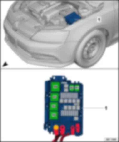
| Slot | Current flow diagram designation | Nominal value | Function/component | Terminal |
| F1 | Not assigned | - | | - |
| F2 | Fuse 2 on fuse holder B -SB2- | 20 A | Engine control unit -J623- | 87 |
| F3 | Fuse 3 on fuse holder B -SB3- | 5 A | High heat output relay -J360- | 87 |
| | | | Low heat output relay -J359- | |
| | | | Radiator fan control unit -J293- | |
| F4 | Fuse 4 on fuse holder B -SB4- | 10 A3)
15 A6) | Lambda probe heater -Z19- | 87 |
| | | | Lambda probe 1 heater after catalytic converter -Z29- | |
| | | | Coolant pump for high-temperature circuit -V467-3) | |
| | | | Low-temperature circuit coolant pump -V468- | |
| | | | Lambda probe heater 2 -Z28- | |
| F5 | Fuse 5 on fuse holder B -SB5-7) | 15 A | Secondary air inlet valve -N112- | 87 |
| F6 | Fuse 6 on fuse holder B -SB6- | 10 A | Fuel system diagnostic pump -V144-
Fuel tank shut-off valve -N288-
Secondary air pump relay -J299-1)
Heater element for crankcase breather -N79-
Lambda probe heater 2 -Z28- | 87 |
| F7 | Fuse 7 on fuse holder B -SB7- | 20 A
30 A5),7) 10 A2),3) | Ignition coil 1 with output stage -N70-
Ignition coil 2 with output stage -N127-
Ignition coil 3 with output stage -N291-
Ignition coil 4 with output stage -N292-
Ignition coil 5 with output stage -N323-5)
Ignition transformer -N152-
Fuel pressure regulating valve -N276-2)4)
Fuel metering valve -N290-2)4)
Camshaft control valve 1 -N205-2) | 87 |
| F8 | Fuse 8 on fuse holder B -SB8- | 10 A | Throttle valve module -J338-
Charge pressure control solenoid valve -N75-
Secondary air inlet valve -N112-
Secondary air pump relay -J299-
Activated charcoal filter solenoid valve 1 -N80-
Camshaft control valve 1 -N205-
Turbocharger air recirculation valve -N249-
Intake manifold flap valve -N316-
Exhaust camshaft control valve 1 -N318-3)
Charge pressure control solenoid valve -N75-4)
Exhaust gas recirculation cooler changeover valve -N345-4)
Heater element for crankcase breather -N79-4)
Valve for oil pressure control -N428-3)
Pressure regulator for disengagement clutch -N511-3)
Radiator blind control motor -V544- | 87 |
| F9 | Fuse 9 on fuse holder B -SB9- | 10 A
15 A3),7) | Fuel pump relay -J17-
Valve for oil pressure control -N428-
Turbocharger air recirculation valve -N249-
Intake manifold flap valve -N316-
Automatic glow period control unit -J179-4)
Circulation pump -V55-4)
Electric fuel pump 2 relay -J49-4) | 87 |
| F10 | Fuse 10 on fuse holder B -SB10- | 5 A | Brake light switch -F-
Clutch position sender -G476- | 87 |
| F11 | Not assigned | - | | - |
| F12 | Fuse 12 on fuse holder B -SB12- | 30 A | Ignition coil 1 with output stage -N70-
Ignition coil 2 with output stage -N127-
Ignition coil 3 with output stage -N291-
Ignition coil 4 with output stage -N292-
Coolant circulation pump -V50- | 87 |
| F13 | Fuse 13 on fuse holder B -SB13- | 30 A8)
20 A8) | Voltage stabiliser -J532-
Control unit with display for radio and navigation -J503-
Radio -R- | 30 |
| F14 | Fuse 14 on fuse holder B -SB14- | 10 A | Engine control unit -J623-
Main relay -J271-4) | 30 |
| F15 | Fuse 15 on fuse holder B -SB15- | 30 A | ABS control unit -J104- | 30 |
| F16 | Fuse 16 on fuse holder B -SB16- | 5 A8)
10 A8)
20 A7),8) | Vacuum pump relay -J57-
Relay for reducing agent metering system -J963- | 30 |
| F17 | Fuse 17 on fuse holder B -SB17- | 15 A | Mechatronic unit for dual clutch gearbox -J743-
Automatic gearbox control unit -J217- | 30 |
| F18 | Fuse 18 on fuse holder B -SB18- | 30 A | Mechatronic unit for dual clutch gearbox -J743- | 30 |
| F19 | Fuse 19 on fuse holder B -SB19- | 5 A | Onboard supply control unit -J519- (T52a/24) AW1, (T73b/59) AW0
Battery monitor control unit -J367- | 30 |
| F20 | Fuse 20 on fuse holder B -SB20- | 30 A | Onboard supply control unit -J519- (AW0)
Wiper motor relay 1 -J368- (AW1)
Wiper motor relay 2 -J369- (AW1) | 30 |
| F21 | Fuse 21 on fuse holder B -SB21- | 40 A7),10)
50 A8) | Secondary air pump motor -V101-
Auxiliary air heater element -Z35- | 87 |
| F22 | Fuse 22 on fuse holder B -SB22- | 40 A10)
30 A11) | Auxiliary air heater element -Z35-
Heated windscreen -Z2- | 87 |
| F23 | Fuse 23 on fuse holder B -SB23- | 40 A8)
50 A8) | Terminal 75 voltage supply relay 1 -J680- | 30 |
| F24 | Fuse 24 on fuse holder B -SB24- | 50 A | Fuse 40 on fuse holder C -SC40- | 30 |
| F25 | Fuse 25 on fuse holder B -SB25- | 40 A | Terminal 15 voltage supply relay -J329- | 30 |
| F26 | Fuse 26 on fuse holder B -SB26- | 50 A
40 A3) | Automatic glow period control unit -J179- | 30 |
| F27 | Fuse 27 on fuse holder B -SB27- | 50 A | Radiator fan -V7- | 30 |
| F28 | Fuse 28 on fuse holder B -SB28-9) | 30 A | Onboard supply control unit -J519- (T52a/1) | 30 |
| F29 | Fuse 29 on fuse holder B -SB29-9) | 30 A | Onboard supply control unit -J519- (T52c/42) | 30 |
| F30 | Fuse 30 on fuse holder B -SB30- | 40 A | ABS control unit -J104- | 30 |
| F31 | Fuse 31 on fuse holder B -SB31- | 40 A | Amplifier -R12- | 30 |
| F32 | Fuse 32 on fuse holder B -SB32- | 40 A | Auxiliary air heater element -Z35- | 30 |
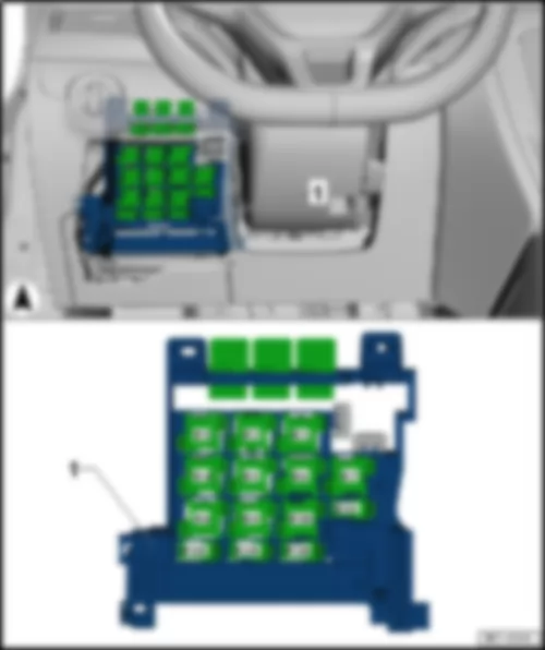
| Slot | Current flow diagram designation | Nominal value | Function/component | Terminal |
| F1 | Fuse 1 on fuse holder C -SC1- | 10 A | Control unit for electronic steering column lock -J764- (T16v/2) | 15 |
| F2 | Not assigned | - | | - |
| F3 | Fuse 3 on fuse holder C -SC3- | 10 A | Control unit in dash panel insert -J285- , (T32/32)
Headlight washer system relay -J39-1) | 30/
30 stabilised |
| F4 | Fuse 4 on fuse holder C -SC4- | 5 A | Telephone transmitter and receiver unit -R36-
Navigation system interface -R94-
Mobile telephone operating electronics control unit -J412- , (T54a/1)
Magnetic field sender for compass -G197- , (T8ac/1) | 30
30 stabilised |
| F5 | Not assigned | - | | - |
| F6 | Fuse 6 on fuse holder C -SC6- | 10 A | Reversing camera -R189- | 30 |
| F7 | Not assigned | - | | - |
| F8 | Fuse 8 on fuse holder C -SC8- | 10 A | Washer pump -V5- , (only AW0)
Onboard supply control unit -J519- , (T73b/61), (only AW0) | 53c |
| F9 | Fuse 9 on fuse holder C -SC9- | 5 A | Airbag control unit -J234-
Front passenger airbag deactivated warning lamp -K145-
Seat occupied recognition control unit -J706- | 15 |
| F10 | Fuse 10 on fuse holder C -SC10- | 15 A | Right steering column switch -EX20- , (T10ls/3), (only AW0) | 15 |
| F11 | Fuse 11 on fuse holder C -SC11- | 10 A | Front left headlight -MX1- , (gas discharge headlight) | 15 |
| F12 | Fuse 12 on fuse holder C -SC12- | 10 A | Front right headlight -MX2- , (gas discharge headlight) | 15 |
| F13 | Fuse 13 on fuse holder C -SC13- | 5 A | Automatic anti-dazzle interior mirror -Y7-
Light sensor -G399-
Parking aid control unit -J446-
Air quality sensor -G238-
High-pressure sender -G65-
Tyre Pressure Loss Indicator button -E492-
Button for TCS and electronic stabilisation program -E256-
Reversing light switch -F4-
Start/Stop operation switch -E262-
Control unit for air conditioning compressor -J842-2)
Control unit for cornering light and headlight range control -J745-
Traction control system switch -E132-
Isolation relay for powertrain CAN bus -J788-
Heater control unit -J162-
Radio -R-
Adaptive cruise control unit -J428-
| 15 |
| F14 | Fuse 14 on fuse holder C -SC14- | 10 A | Left steering column switch -EX19- , (T16ls/1), (only AW0)
ABS control unit -J104- , T26/20 / T47/8)
Airbag coil connector and return ring with slip ring -F138- , (T16k/14)
Trailer detector control unit -J345- , (T12a/2)
Voltage stabiliser -J532-
DC/AC converter with socket, 12 V - 230 V -U13- , (T3wr/3)
Control unit for vehicle location system -J895-
Data bus diagnostic interface -J533- , (only AW1)
Control unit in dash panel insert -J285-
Data bus diagnostic interface -J533-
Hybrid battery unit -AX1- (T14ax/7)2)
Power and control electronics for electric drive -JX1- (T28jx/56)
Power steering control unit -J500-
Oil level and oil temperature sender -G266- | 15 |
| F15 | Fuse 15 on fuse holder C -SC15- | 15 A | Diagnostic connection -U31-
Switch and instrument illumination regulator -E20-
Headlight range control regulator -E102- , (only AW1)
Auxiliary heater operation relay -J485- , (T9st/1)
Driver vanity mirror contact switch -F147- , (T3be/3)
Light switch -E1- , (T10h/4)
Front left headlight -MX1-
Left headlight range control motor -V48-
Front right headlight -MX2-
Right headlight range control motor -V49-
Onboard supply control unit -J519- (T73a/44) | 15 |
| F16 | Fuse 16 on fuse holder C -SC16- | 10 A | Starter relay 1 -J906- , (T9c/1)
Starter relay 2 -J907- , (T7a/1)
Air mass meter -G70- , T3bg/2)
Fuel pump control unit -J538-
Engine control unit -J623-
Button for extended electric drive mode -E709-
Cold start device relay -J41- , (T9ks/1) | 15 |
| F17 | Fuse 17 on fuse holder C -SC17- | 10 A | Control unit for structure-borne sound -J869-
Blind Spot Monitor control unit 2 -J1087-
Blind spot monitor control unit -J1086- | 15 |
| F18 | Fuse 18 on fuse holder C -SC18-3) | 10 A | Left steering column switch -EX19-
Right steering column switch -EX20- | TFL |
| F19 | Not assigned | - | | - |
| F20 | Fuse 20 on fuse holder C -SC20- | 10 A | Remote control receiver for auxiliary coolant heater -R149-
Rain and light sensor -G397-
Heater control unit -J162-
Diagnostic connection -U31- | 30 |
| F21 | Fuse 21 on fuse holder C -SC21- | 15 A | Heated front seats control unit -J774- | 30 |
| F22 | Fuse 22 on fuse holder C -SC22- | 10 A4)
15 A3) | Onboard supply control unit -J519- , (T52c/1)
Alarm system relay 5, hazard warning lights -J464-
Interior monitoring sensor -G273-
Vehicle inclination sender -G384-
Alarm horn -H12- | 30 |
| F23 | Fuse 23 on fuse holder C -SC23- | 10 A | Onboard supply control unit -J519- , (T73b/39) (only AW0)
Light switch -E1- , (only AW1)
Ignition/starter switch -D- (AW0)
Control unit for vehicle location system -J895-
Selector lever sensors control unit -J587-
Automatic gearbox control unit -J217- | 30 |
| F24 | Fuse 24 on fuse holder C -SC24- | 10 A | Entry and start authorisation control unit -J518- | 30 |
| F25 | Fuse 25 on fuse holder C -SC25- | 10 A | Mechatronic unit for dual clutch gearbox -J743-
Selector lever sensors control unit -J587-
Automatic gearbox control unit -J217-
Multifunction switch -F125- | 15 |
| F26 | Fuse 26 on fuse holder C -SC26- | 20 A | Vacuum pump for brakes -V192- | 15 |
| F27 | Fuse 27 on fuse holder C -SC27-3) | 1 A | Airbag coil connector and return ring with slip ring -F138- , (T16k/1) | 15 |
| F28 | Fuse 28 on fuse holder C -SC28- | 10 A | Left washer jet heater element -Z20-
Right washer jet heater element -Z21- | 75 |
| F29 | Fuse 29 on fuse holder C -SC29-3) | 5 A | Onboard supply control unit -J519- , (T73b/51) (only AW0) | 75 |
| F30 | Fuse 30 on fuse holder C -SC30- | 20 A | Onboard supply control unit -J519- , (T52c/21)
Cigarette lighter -U1-
12 V socket -U5-
12 V socket 2 -U18-
Blocking diode -J29- | 75 |
| F31 | Not assigned | - | | - |
| F32 | Not assigned | - | | - |
| F33 | Fuse 33 on fuse holder C -SC33- | 40 A | Auxiliary heater operation relay -J485-
Air conditioning system control unit -J301- | 75 |
| F34 | Not assigned | - | | 56 |
| F35 | Fuse 35 on fuse holder C -SC35- | 10 A | Steering column electronics control unit -J527- , (only AW1)
Data bus diagnostic interface -J533- , (only AW1)
Onboard supply control unit -J519- , (T73a/66) | 30 |
| F36 | Fuse 36 on fuse holder C -SC36- | 20 A | Headlight washer system relay -J39-
Onboard supply control unit -J519- , (T73a/73)(only AW0) | 30 |
| F37 | Fuse 37 on fuse holder C -SC37- | 30 A | DC/AC converter with socket, 12 V - 230 V -U13- | 30 |
| F38 | Fuse 38 on fuse holder C -SC38- | 15 A3)
30 A | Auxiliary heater control unit -J364-
Fan enabling relay -J937- | 30 |
| F39 | Fuse 39 on fuse holder C -SC39- | 30 A | Control unit for reducing-agent heater -J891- | 56b |
| F40 | Fuse 40 on fuse holder C -SC40- | 20 A | Trailer detector control unit -J345- , (T12a/9) | 30 |
| F41 | Fuse 41 on fuse holder C -SC41- | 15 A | Trailer detector control unit -J345- , (T12a/12) | 30 |
| F42 | Fuse 42 on fuse holder C -SC42- | 20 A | Trailer detector control unit -J345- (T12a/11) | 30 |
| F43 | Fuse 43 on fuse holder C -SC43- | 10 A | Converter box -J935-
Heated rear window relay -J9-
Dual tone horn relay -J4-
Ignition/starter switch -D-
| 30 |
| F44 | Fuse 44 on fuse holder C -SC44- | 30 A | Heated rear window relay -J9- , (only AW1)
Heated rear window -Z1-
Onboard supply control unit -J519- , (T73b/67) (only AW0)
Auxiliary heater operation relay 2 -J1026- | 30 |
| F45 | Fuse 45 on fuse holder C -SC45- | 30 A | Driver door control unit -J386-
Rear left door control unit -J388- | 30 |
| F46 | Fuse 46 on fuse holder C -SC46- | 30 A | Rear left door control unit -J388-
Rear right door control unit -J389- | 30 |
| F47 | Fuse 47 on fuse holder C -SC47- | 15 A5)
20 A5) | Fuel pump control unit -J538-
Fuel pump relay -J17-
Cold start device relay -J41- | 30 |
| F48 | Fuse 48 on fuse holder C -SC48- | 20 A | Onboard supply control unit -J519- , (T52b/42) (only AW1)
Onboard supply control unit -J519- , (T73b/11) (only AW0)
Onboard supply control unit -J519- , (T73b/13) (only AW0) | 30 |
| F49 | Fuse 49 on fuse holder C -SC49- | 40 A | Auxiliary heater operation relay -J485-
Climatronic control unit -J255-
Air conditioning system control unit -J301-
Heater control unit -J162- | 30 |
| F50 | Fuse 50 on fuse holder C -SC50- | 30 A | Heated front seats control unit -J774- | 30 |
| F51 | Fuse 51 on fuse holder C -SC51- | 20 A | Sliding sunroof adjustment control unit -J245- | 30 |
| F52 | Fuse 52 on fuse holder C -SC52- | 20 A | Headlight washer system relay -J39-
Headlight washer system pump -V11- | 30 |
| F53 | Fuse 53 on fuse holder C -SC53- | 30 A | Onboard supply control unit -J519- , (T52b/1) (only AW1)
Onboard supply control unit -J519- , (T73a/16), (only AW0) | 30 |
| F54 | Not assigned | - | | - |
| F55 | Fuse 55 on fuse holder C -SC55- | 15 A | Two-way radio socket -U4-
Diagnostic connection -U31- | 30 |
| F56 | Fuse 56 on fuse holder C -SC56-3) | 10 A | Fan enabling relay -J937- | 30 |
| F57 | Fuse 57 on fuse holder C -SC57- | 20 A | Radio -R-
Control unit with display for radio and navigation -J503- | 30 |
| F58 | Fuse 58 on fuse holder C -SC58-3) | 20 A | Onboard supply control unit -J519- , (T73a/63) (only AW0) | 30 |
| F59 | Fuse 59 on fuse holder C -SC59-3) | 20 A | Onboard supply control unit -J519- , (T73b/68) (only AW0) | 30 |
| F60 | Fuse 60 on fuse holder C -SC60-3) | 20 A | Left steering column switch -EX19-
Right steering column switch -EX20- | 30 |
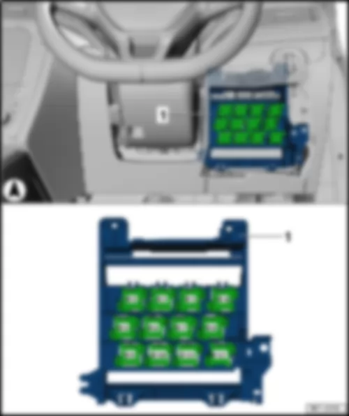
| Slot | Current flow diagram designation | Nominal value | Function/component | Terminal |
| F1 | Fuse 1 on fuse holder C -SC1- | 10 A | Control unit for electronic steering column lock -J764- (T16v/2) | 15 |
| F2 | Not assigned | - | | - |
| F3 | Fuse 3 on fuse holder C -SC3- | 10 A | Control unit in dash panel insert -J285- , (T32/32)
Headlight washer system relay -J39-1) | 30/
30 stabilised |
| F4 | Fuse 4 on fuse holder C -SC4- | 5 A | Telephone transmitter and receiver unit -R36-
Navigation system interface -R94-
Mobile telephone operating electronics control unit -J412- , (T54a/1)
Magnetic field sender for compass -G197- , (T8ac/1) | 30
30 stabilised |
| F5 | Not assigned | - | | - |
| F6 | Fuse 6 on fuse holder C -SC6- | 10 A | Reversing camera -R189- | 30 |
| F7 | Not assigned | - | | - |
| F8 | Fuse 8 on fuse holder C -SC8- | 10 A | Washer pump -V5- , (only AW0)
Onboard supply control unit -J519- , (T73b/61), (only AW0) | 53c |
| F9 | Fuse 9 on fuse holder C -SC9- | 5 A | Airbag control unit -J234-
Front passenger airbag deactivated warning lamp -K145-
Seat occupied recognition control unit -J706- | 15 |
| F10 | Fuse 10 on fuse holder C -SC10- | 15 A | Right steering column switch -EX20- , (T10ls/3), (only AW0) | 15 |
| F11 | Fuse 11 on fuse holder C -SC11- | 10 A | Front left headlight -MX1- , (gas discharge headlight) | 15 |
| F12 | Fuse 12 on fuse holder C -SC12- | 10 A | Front right headlight -MX2- , (gas discharge headlight) | 15 |
| F13 | Fuse 13 on fuse holder C -SC13- | 5 A | Automatic anti-dazzle interior mirror -Y7-
Light sensor -G399-
Parking aid control unit -J446-
Air quality sensor -G238-
High-pressure sender -G65-
Tyre Pressure Loss Indicator button -E492-
Button for TCS and electronic stabilisation program -E256-
Reversing light switch -F4-
Start/Stop operation switch -E262-
Control unit for air conditioning compressor -J842-2)
Control unit for cornering light and headlight range control -J745-
Traction control system switch -E132-
Isolation relay for powertrain CAN bus -J788-
Heater control unit -J162-
Radio -R-
Adaptive cruise control unit -J428-
| 15 |
| F14 | Fuse 14 on fuse holder C -SC14- | 10 A | Left steering column switch -EX19- , (T16ls/1), (only AW0)
ABS control unit -J104- , T26/20 / T47/8)
Airbag coil connector and return ring with slip ring -F138- , (T16k/14)
Trailer detector control unit -J345- , (T12a/2)
Voltage stabiliser -J532-
DC/AC converter with socket, 12 V - 230 V -U13- , (T3wr/3)
Control unit for vehicle location system -J895-
Data bus diagnostic interface -J533- , (only AW1)
Control unit in dash panel insert -J285-
Data bus diagnostic interface -J533-
Hybrid battery unit -AX1- (T14ax/7)2)
Power and control electronics for electric drive -JX1- (T28jx/56)
Power steering control unit -J500-
Oil level and oil temperature sender -G266- | 15 |
| F15 | Fuse 15 on fuse holder C -SC15- | 15 A | Diagnostic connection -U31-
Switch and instrument illumination regulator -E20-
Headlight range control regulator -E102- , (only AW1)
Auxiliary heater operation relay -J485- , (T9st/1)
Driver vanity mirror contact switch -F147- , (T3be/3)
Light switch -E1- , (T10h/4)
Front left headlight -MX1-
Left headlight range control motor -V48-
Front right headlight -MX2-
Right headlight range control motor -V49-
Onboard supply control unit -J519- (T73a/44) | 15 |
| F16 | Fuse 16 on fuse holder C -SC16- | 10 A | Starter relay 1 -J906- , (T9c/1)
Starter relay 2 -J907- , (T7a/1)
Air mass meter -G70- , T3bg/2)
Fuel pump control unit -J538-
Engine control unit -J623-
Button for extended electric drive mode -E709-
Cold start device relay -J41- , (T9ks/1) | 15 |
| F17 | Fuse 17 on fuse holder C -SC17- | 10 A | Control unit for structure-borne sound -J869-
Blind Spot Monitor control unit 2 -J1087-
Blind spot monitor control unit -J1086- | 15 |
| F18 | Fuse 18 on fuse holder C -SC18-3) | 10 A | Left steering column switch -EX19-
Right steering column switch -EX20- | TFL |
| F19 | Not assigned | - | | - |
| F20 | Fuse 20 on fuse holder C -SC20- | 10 A | Remote control receiver for auxiliary coolant heater -R149-
Rain and light sensor -G397-
Heater control unit -J162-
Diagnostic connection -U31- | 30 |
| F21 | Fuse 21 on fuse holder C -SC21- | 15 A | Heated front seats control unit -J774- | 30 |
| F22 | Fuse 22 on fuse holder C -SC22- | 10 A4)
15 A3) | Onboard supply control unit -J519- , (T52c/1)
Alarm system relay 5, hazard warning lights -J464-
Interior monitoring sensor -G273-
Vehicle inclination sender -G384-
Alarm horn -H12- | 30 |
| F23 | Fuse 23 on fuse holder C -SC23- | 10 A | Onboard supply control unit -J519- , (T73b/39) (only AW0)
Light switch -E1- , (only AW1)
Ignition/starter switch -D- (AW0)
Control unit for vehicle location system -J895-
Selector lever sensors control unit -J587-
Automatic gearbox control unit -J217- | 30 |
| F24 | Fuse 24 on fuse holder C -SC24- | 10 A | Entry and start authorisation control unit -J518- | 30 |
| F25 | Fuse 25 on fuse holder C -SC25- | 10 A | Mechatronic unit for dual clutch gearbox -J743-
Selector lever sensors control unit -J587-
Automatic gearbox control unit -J217-
Multifunction switch -F125- | 15 |
| F26 | Fuse 26 on fuse holder C -SC26- | 20 A | Vacuum pump for brakes -V192- | 15 |
| F27 | Fuse 27 on fuse holder C -SC27-3) | 1 A | Airbag coil connector and return ring with slip ring -F138- , (T16k/1) | 15 |
| F28 | Fuse 28 on fuse holder C -SC28- | 10 A | Left washer jet heater element -Z20-
Right washer jet heater element -Z21- | 75 |
| F29 | Fuse 29 on fuse holder C -SC29-3) | 5 A | Onboard supply control unit -J519- , (T73b/51) (only AW0) | 75 |
| F30 | Fuse 30 on fuse holder C -SC30- | 20 A | Onboard supply control unit -J519- , (T52c/21)
Cigarette lighter -U1-
12 V socket -U5-
12 V socket 2 -U18-
Blocking diode -J29- | 75 |
| F31 | Not assigned | - | | - |
| F32 | Fuse 32 on fuse holder C -SC32-6) | 15 A | Magnetic clutch relay -J44- | 75 |
| F33 | Fuse 33 on fuse holder C -SC33- | 40 A | Auxiliary heater operation relay -J485-
Air conditioning system control unit -J301- | 75 |
| F34 | Not assigned | - | | 56 |
| F35 | Fuse 35 on fuse holder C -SC35- | 10 A | Steering column electronics control unit -J527- , (only AW1)
Data bus diagnostic interface -J533- , (only AW1)
Onboard supply control unit -J519- , (T73a/66) | 30 |
| F36 | Fuse 36 on fuse holder C -SC36- | 20 A | Headlight washer system relay -J39-
Onboard supply control unit -J519- , (T73a/73)(only AW0) | 30 |
| F37 | Fuse 37 on fuse holder C -SC37- | 30 A | DC/AC converter with socket, 12 V - 230 V -U13- | 30 |
| F38 | Fuse 38 on fuse holder C -SC38- | 15 A3)
30 A | Auxiliary heater control unit -J364-
Fan enabling relay -J937- | 30 |
| F39 | Fuse 39 on fuse holder C -SC39- | 30 A | Control unit for reducing-agent heater -J891- | 56b |
| F40 | Fuse 40 on fuse holder C -SC40- | 20 A | Trailer detector control unit -J345- , (T12a/9) | 30 |
| F41 | Fuse 41 on fuse holder C -SC41- | 15 A | Trailer detector control unit -J345- , (T12a/12) | 30 |
| F42 | Fuse 42 on fuse holder C -SC42- | 20 A | Trailer detector control unit -J345- (T12a/11) | 30 |
| F43 | Fuse 43 on fuse holder C -SC43- | 10 A | Converter box -J935-
Heated rear window relay -J9-
Dual tone horn relay -J4-
Ignition/starter switch -D-
| 30 |
| F44 | Fuse 44 on fuse holder C -SC44- | 30 A | Heated rear window relay -J9- , (only AW1)
Heated rear window -Z1-
Onboard supply control unit -J519- , (T73b/67) (only AW0)
Auxiliary heater operation relay 2 -J1026- | 30 |
| F45 | Fuse 45 on fuse holder C -SC45- | 30 A | Driver door control unit -J386-
Rear left door control unit -J388- | 30 |
| F46 | Fuse 46 on fuse holder C -SC46- | 30 A | Rear left door control unit -J388-
Rear right door control unit -J389- | 30 |
| F47 | Fuse 47 on fuse holder C -SC47- | 15 A5)
20 A5) | Fuel pump control unit -J538-
Fuel pump relay -J17-
Cold start device relay -J41- | 30 |
| F48 | Fuse 48 on fuse holder C -SC48- | 20 A | Onboard supply control unit -J519- , (T52b/42) (only AW1)
Onboard supply control unit -J519- , (T73b/11) (only AW0)
Onboard supply control unit -J519- , (T73b/13) (only AW0) | 30 |
| F49 | Fuse 49 on fuse holder C -SC49- | 40 A | Auxiliary heater operation relay -J485-
Climatronic control unit -J255-
Air conditioning system control unit -J301-
Heater control unit -J162- | 30 |
| F50 | Fuse 50 on fuse holder C -SC50- | 30 A | Heated front seats control unit -J774- | 30 |
| F51 | Fuse 51 on fuse holder C -SC51- | 20 A | Sliding sunroof adjustment control unit -J245- | 30 |
| F52 | Fuse 52 on fuse holder C -SC52- | 20 A | Headlight washer system relay -J39-
Headlight washer system pump -V11- | 30 |
| F53 | Fuse 53 on fuse holder C -SC53- | 30 A | Onboard supply control unit -J519- , (T52b/1) (only AW1)
Onboard supply control unit -J519- , (T73a/16), (only AW0) | 30 |
| F54 | Not assigned | - | | - |
| F55 | Fuse 55 on fuse holder C -SC55- | 15 A | Two-way radio socket -U4-
Diagnostic connection -U31- | 30 |
| F56 | Fuse 56 on fuse holder C -SC56-3) | 10 A | Fan enabling relay -J937- | 30 |
| F57 | Fuse 57 on fuse holder C -SC57- | 20 A | Radio -R-
Control unit with display for radio and navigation -J503- | 30 |
| F58 | Fuse 58 on fuse holder C -SC58-3) | 20 A | Onboard supply control unit -J519- , (T73a/63) (only AW0) | 30 |
| F59 | Fuse 59 on fuse holder C -SC59-3) | 20 A | Onboard supply control unit -J519- , (T73b/68) (only AW0) | 30 |
| F60 | Fuse 60 on fuse holder C -SC60-3) | 20 A | Left steering column switch -EX19-
Right steering column switch -EX20- | 30 |

 Deutsch
 English
 English
 Español
 Nederlands
 Русский

