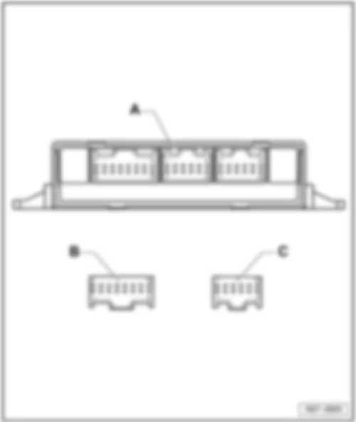
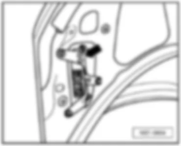
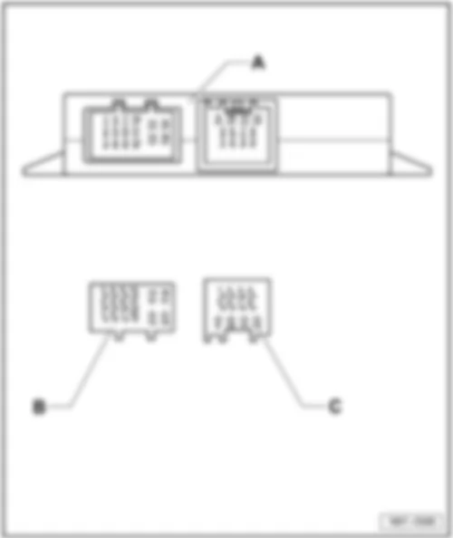
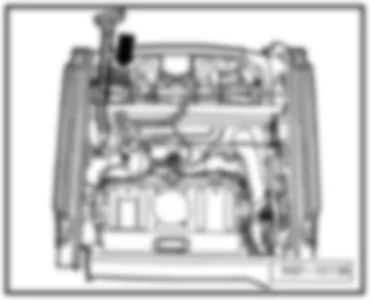
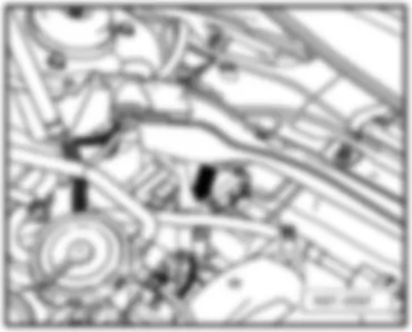
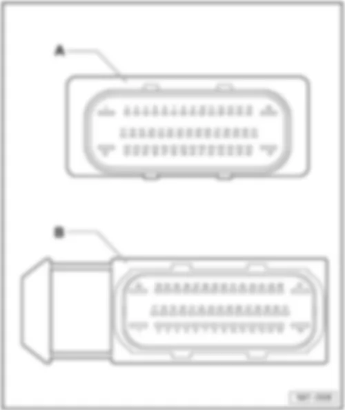
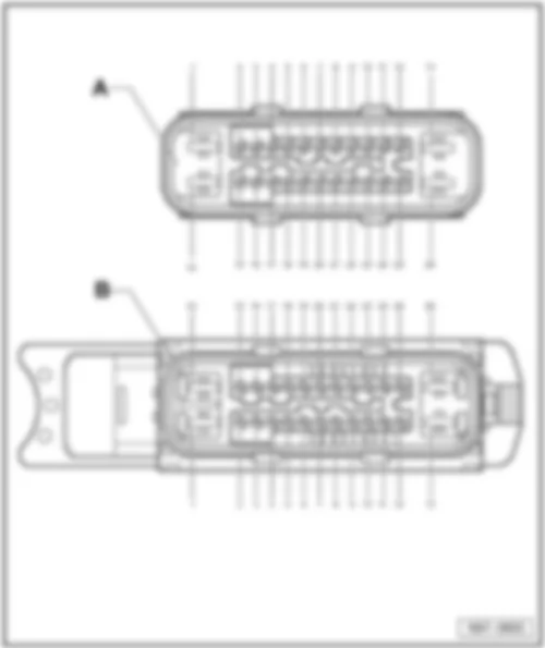
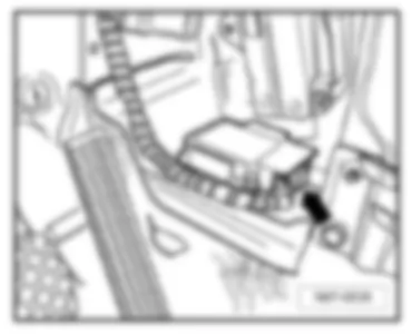
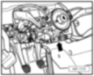
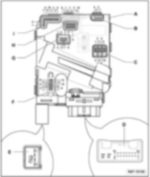
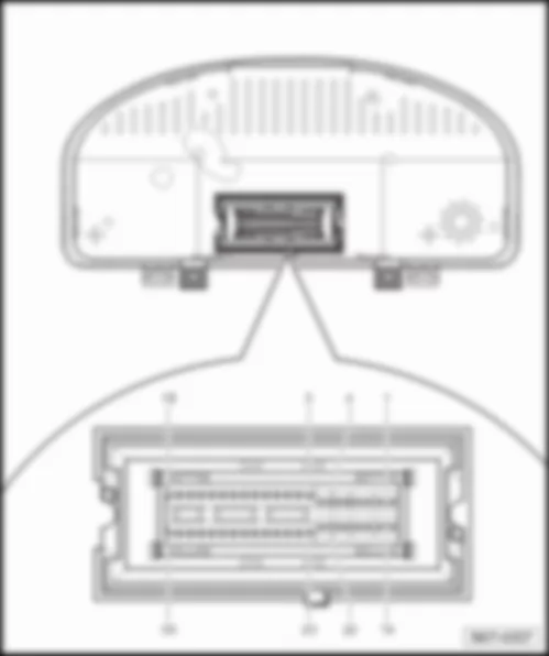
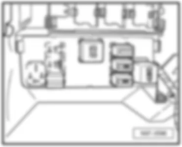
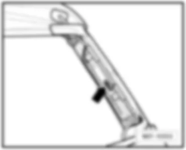
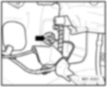
Wiring Diagram VW GOLF PLUS 2005 - Mobile telephone operating electronics control unit - terminal 15 voltage supply relay
Wiring Diagram VW GOLF PLUS 2005 - Mobile telephone operating electronics control unit - telephone microphone - radio
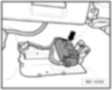
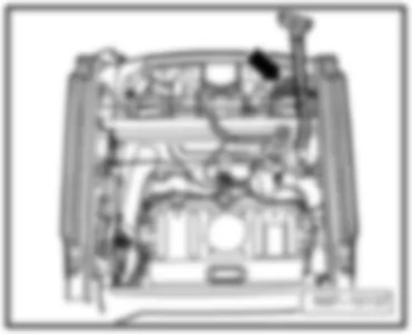
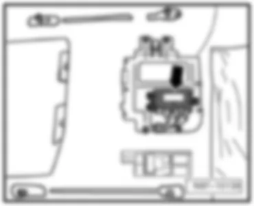
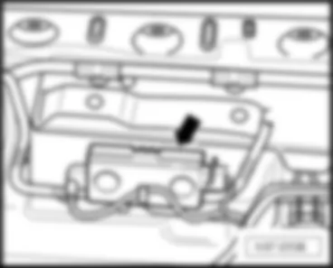
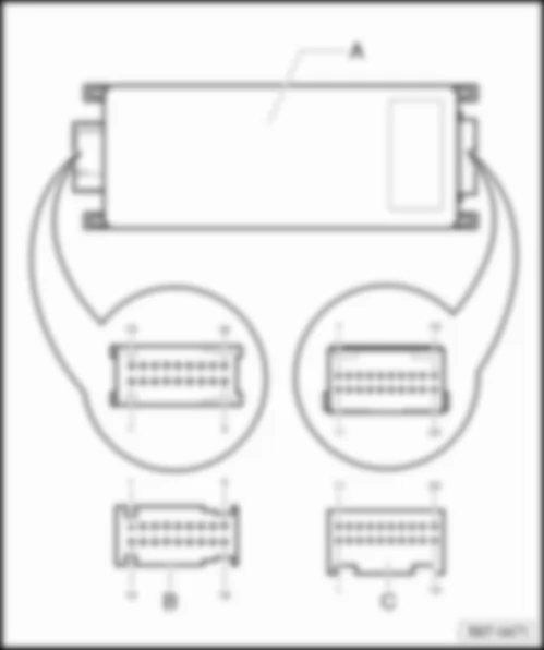
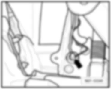
| J412 | Mobile telephone operating electronics control unit, under front passenger seat |
| J519 | Onboard supply control unit |
| J533 | Data bus diagnostic interface |
| R | Radio |
| R38 | Telephone microphone |
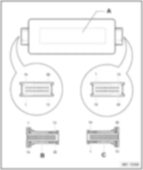
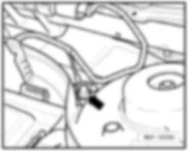
| T2f | 2-pin connector, near front interior light |
| T12g | 12-pin connector |
| T18b | 18-pin connector |
| T16b | 16-pin connector |
| T20 | 20-pin connector |
| 45 | Earth point, centre behind dash panel |
| 370 | Earth connection 5, in main wiring harness |
| 371 | Earth connection 6, in main wiring harness |
| A178 | Connection (infotainment CAN bus, high), in dash panel wiring harness |
| A179 | Connection (infotainment CAN bus, low), in dash panel wiring harness |
| B340 | Connection 1 (58d), in main wiring harness |
| *** | component not included in the telephone preparation |
Wiring Diagram VW GOLF PLUS 2005 - Mobile telephone operating electronics control unit - mobile telephone
Wiring Diagram VW GOLF PLUS 2005 - Mobile telephone - aerial filter - aerial
| J503 | Control unit with display for radio and navigation system |
| J519 | Onboard supply control unit |
| R54 | Mobile telephone |
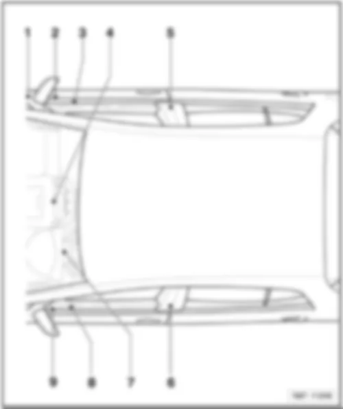
| T1k | Single pin connector, near roof aerial |
| T1l | Single pin connector, near roof aerial |
| R50 | Navigation system aerial |
| R65 | Telephone aerial |
| R87 | Aerial filter, rear right side panel |
| R149 | Remote control receiver for auxiliary coolant heater |
| R182 | Auxiliary heater aerial |
| *** | component not included in the telephone preparation |
| --- | only models with radio navigation system |
| -●-●- | only models with telephone /telephone preparation |
| -●●- | only models with radio navigation system, telephone and auxiliary heater |
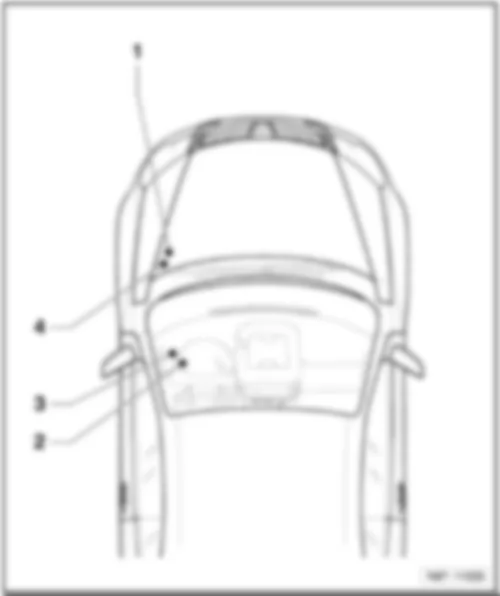
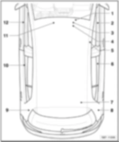
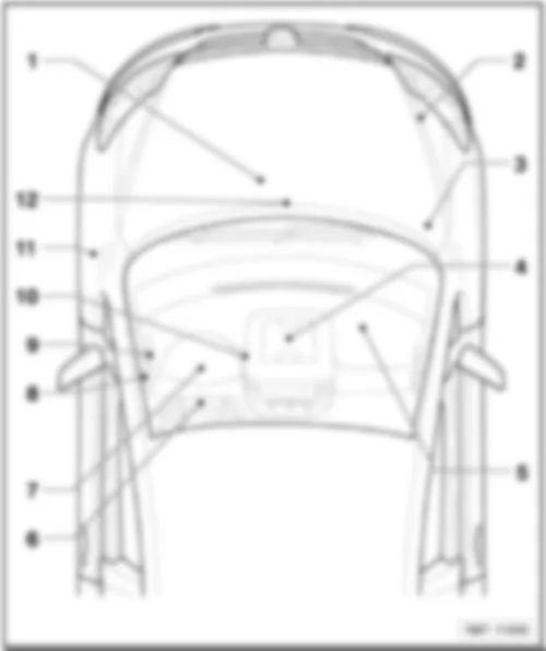
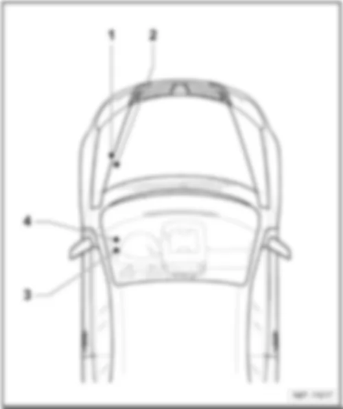
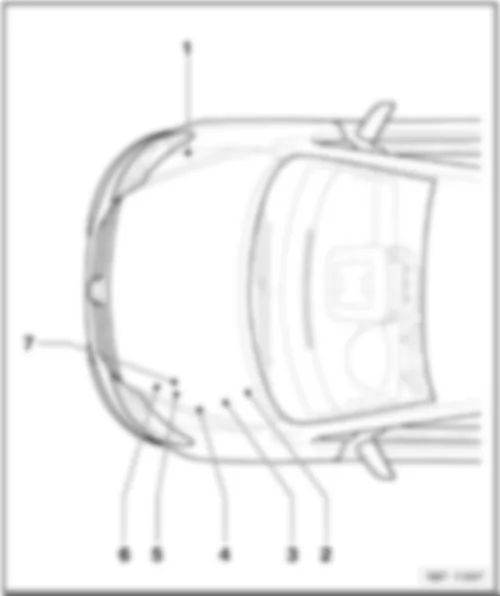
VW GOLF PLUS 2005 Overview of relay carrier
Overview of relay carrier | | | | 1 - | Relay carrier on E-box |
| q | On left in engine compartment |
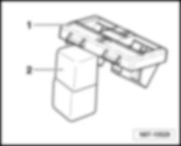
| 2 - | Relay carrier on onboard supply control unit |
| 3 - | Relay carrier on left under dash panel |
| 4 - | Additional relay carrier under E-box |
| q | Under E-box, on left in engine compartment |
| q | Relay assignment, to April 2005 ⇒ page → 803/3 |
| Golf Plus | Fitting Locations | No. 803 / 2 |
|
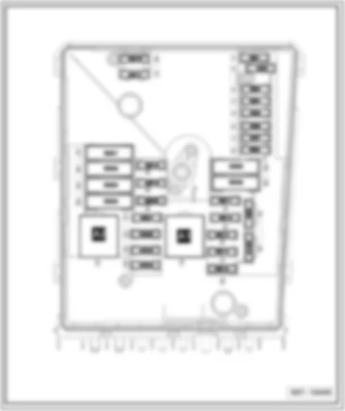
| Relay locations on E-box low |
| 1 - | Terminal 30 voltage supply relay -J317- (458) |
| 1 - | Terminal 30 voltage supply relay -J317- (100) |
| 2 - | Secondary air pump relay -J299- (100) |
| q | Engine code BSX, from May 2005 |
| 2 - | Wiring bridge for automatic glow period control unit -J179- Glow plugs 1...4 -Q10...Q13- |
| q | Only vehicles with diesel engine |
| Golf Plus | Fitting Locations | No. 803 / 3 |
|
VW GOLF PLUS 2005 Relay locations on E-box high
Relay locations on E-box high |
| 1 - | Terminal 15 voltage supply relay -J329- (433) |
| 2 - | Relay for voltage supply of term. 50 -J682- (433) |
| 3 - | Engine components current supply relay -J757- (167) |
| 4 - | Terminal 30 voltage supply relay -J317- (458) |
| Golf Plus | Fitting Locations | No. 803 / 4 |
|
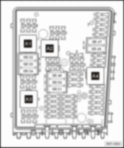
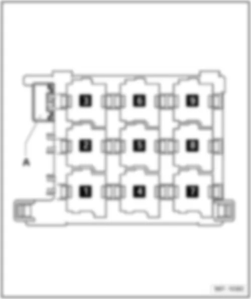
VW GOLF PLUS 2005 Relay assignment, relay carrier on onboard supply control unit, on left under dash panel
Relay assignment, relay carrier on onboard supply control unit, on left under dash panel |
| 1 - | Terminal 15 voltage supply relay 2 -J681- (460) |
| 2 - | Heated exterior mirror relay -J99- (449) |
| 3 - | Heated rear window relay -J9- (53) |
| 4 - | Dual tone horn relay -J4- (449) |
| 4 - | Horn relay -J413- (449) |
| 5 - | X-contact relief relay -J59- (460) |
| 6 - | Relay 1 for double washer pump -J729- (404) |
| Golf Plus | Fitting Locations | No. 803 / 5 |
|
| 6 - | Relay 2 for double washer pump -J730- (404) |
| 7 - | Relay 2 for double washer pump -J730- (404) |
| 7 - | Relay 1 for double washer pump -J729- (404) |
| 9 - | Terminal 30 voltage supply relay 2 -J689- (449) |
| Golf Plus | Fitting Locations | No. 803 / 6 |
|
VW GOLF PLUS 2005 Relay assignment on left under dash panel, to April 2006
Relay assignment on left under dash panel, to April 2006 |
| 2 - | Terminal 50 voltage supply relay -J682- (433) |
| 3 - | Headlight washer system relay -J39- (53) |
| 5 - | Fresh air blower relay -J13- (404) |
| 6 - | Fuel pump relay -J17- (449) |
| 6 - | Relay for auxiliary heating mode -J485- (449) |
| Golf Plus | Fitting Locations | No. 803 / 7 |
|
| A - | Driver seat adjustment thermal fuse 1 - 30A |
Note:
| -J17- and -J485- are located in one relay slot depending on the equipment. |
| Golf Plus | Fitting Locations | No. 803 / 8 |
|
VW GOLF PLUS 2005 Relay assignment on left under dash panel, from May 2006
Relay assignment on left under dash panel, from May 2006 |
| 1 - | Fuel pump relay -J17- (449) |
| 1 - | Fuel supply relay -J643- (449) |
| 2 - | Terminal 50 voltage supply relay -J682- (53) |
| 3 - | Headlight washer system relay -J39- (53) |
| 4 - | Fresh air blower relay -J13- (404) |
| 5 - | Relay for low heater output -J359- (373) |
| 5 - | Fuel pump isolator relay -J333- (404) |
| 6 - | Relay for auxiliary heating mode -J485- (449) |
| Golf Plus | Fitting Locations | No. 803 / 9 |
|
| 6 - | High heat output relay |
| A - | Driver seat adjustment thermal fuse 1 - 30A |
Note:
| -J333-, -J13-, -J485- , -J360- and -J359- are installed depending on the equipment. Micro relays -J17- and -J643- are located in one relay slot |
| Golf Plus | Fitting Locations | No. 803 / 10 |
|
VW GOLF PLUS 2005 Relay assignment on left under dash panel, from May 2007
Relay assignment on left under dash panel, from May 2007 |
| 1 - | Fuel pump relay -J17- (449) |
| 1 - | Fuel system pressurisation relay -J643- (449) |
| 2 - | Relay for voltage supply of term. 50 -J682- (53) |
| 3 - | Headlight washer system relay -J39- (53) |
| 4 - | Fresh air blower relay -J13- (404) |
| 5 - | Relay for auxiliary heating mode -J485- (449) |
| 5 - | Relay for low heater output -J359- (373) |
| 6 - | Fuel pump isolator relay -J333- (404) |
| Golf Plus | Fitting Locations | No. 803 / 11 |
|
| 7 - | Fuel pump isolator relay -J333- (404) |
| 8 - | Relay for additional coolant pump -J496- (449) |
| A - | Driver seat adjustment thermal fuse 1 - 30A |
Note:
| -J333-, -J13-, -J485- , -J360- and -J359- are installed depending on the equipment. Micro relays -J17- and -J643- are located in one relay slot |
| Golf Plus | Fitting Locations | No. 803 / 12 |
|
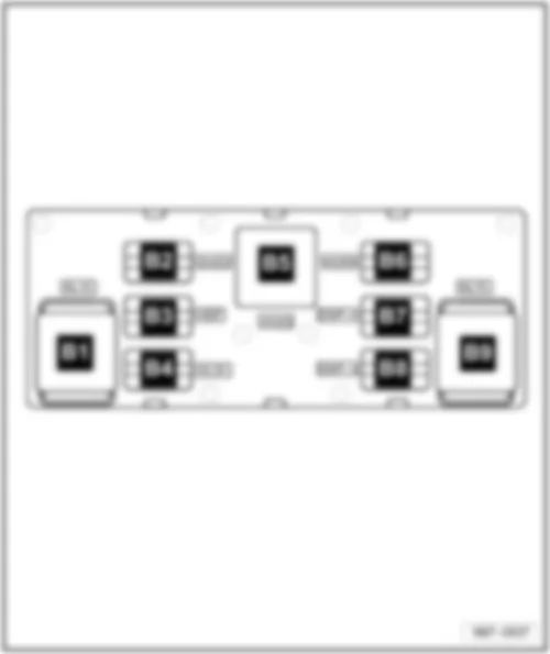
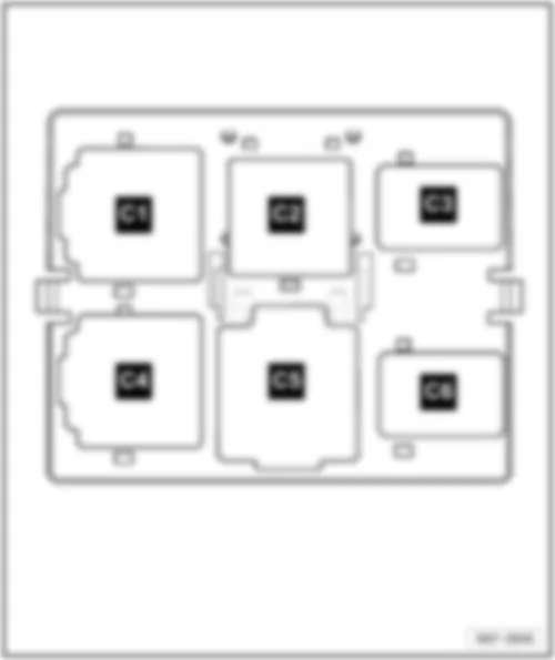
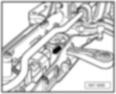
| Relay assignment on additional relay carrier under E-box, on left in engine compartment, to April 2005 |
| 2 - | Automatic glow period control unit -J179- (461) |
Note:
| -The additional relay carrier is located under the E-box and is only visible when removed. |
| Golf Plus | Fitting Locations | No. 803 / 13 |
|
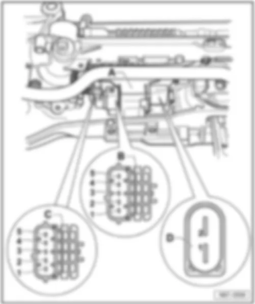
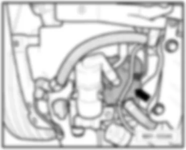
VW GOLF PLUS 2005 Relay assignment on additional relay carrier under E-box, on left in engine compartment, from May 2005 | Relay assignment on additional relay carrier under E-box, on left in engine compartment, from May 2005 | | 1 - | Additional relay carrier under E-box, on left in engine compartment | | 2 - | Automatic glow period control unit -J179- (461), from August 2006 code (457) | | |
|