AUTOMOTIVE ELECTRICIANS PORTAL

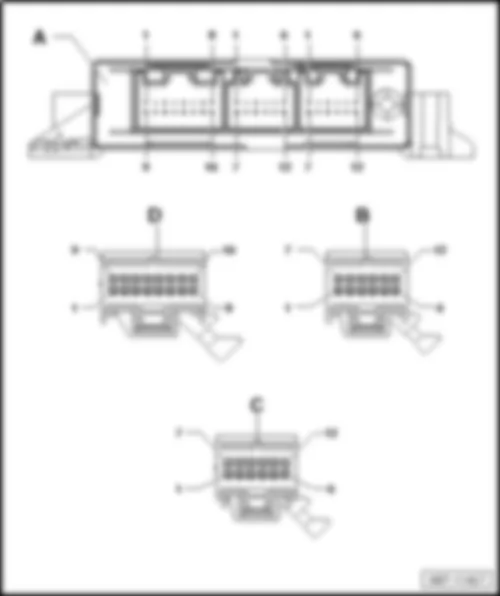
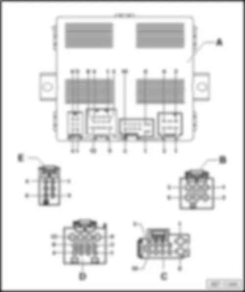
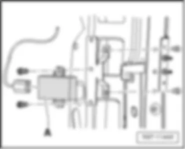
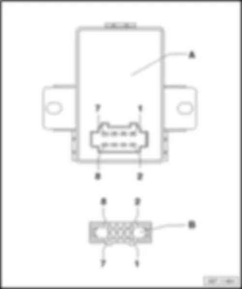
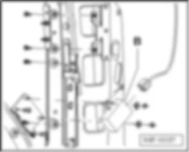
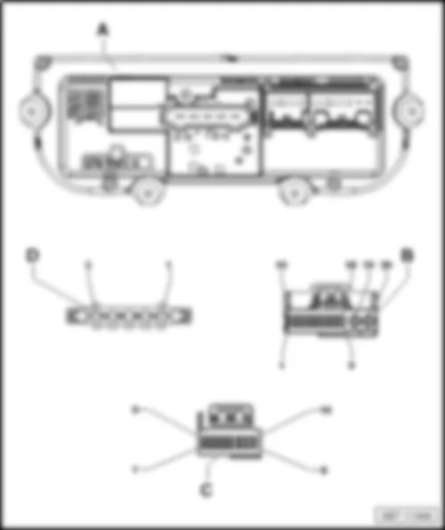
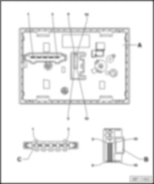
VW TRANSPORTER 2013 – Preparation for mobile telephone, (9W0),(9ZI),(9ZL),(9ZS) . Wiring diagrams, Pin Connector, Location

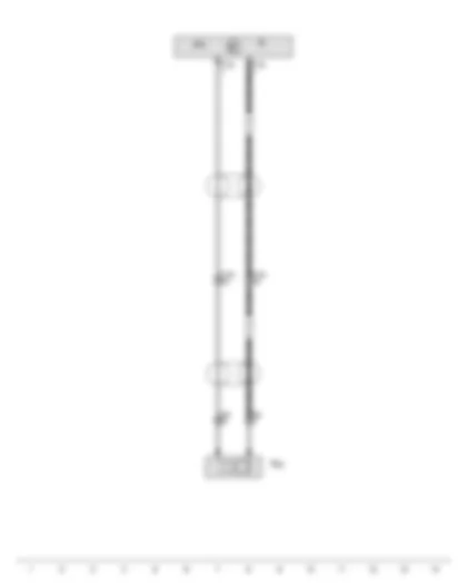
Wiring Diagram VW TRANSPORTER 2013 - Control unit with display for radio and navigation - Radio - Telephone microphone


Wiring Diagram  VW TRANSPORTER 2013 - Control unit with display for radio and navigation - Radio - Telephone microphone https://portal-diagnostov.com/license.html
https://portal-diagnostov.com/license.html Automotive Electricians Portal FZCO Automotive Electricians Portal FZCO
Download PDF file
J503 Control unit with display for radio and navigation
R Radio
R38 Telephone microphone
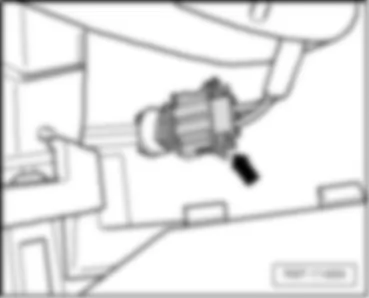
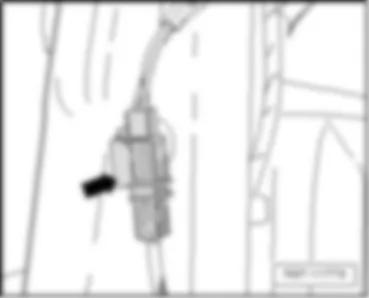
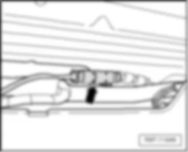
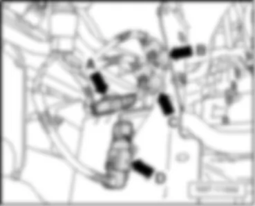
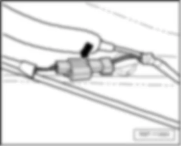
T2r 2-pin connector, black, near front interior light
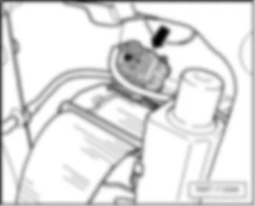
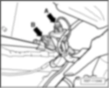
T12p 12-pin connector, green
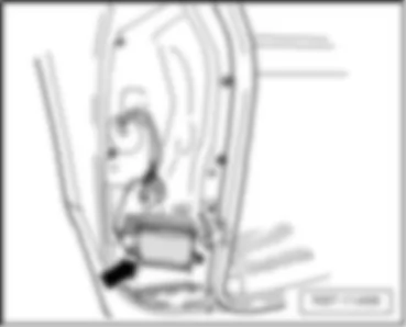
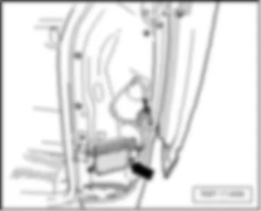
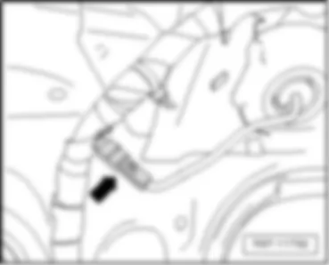
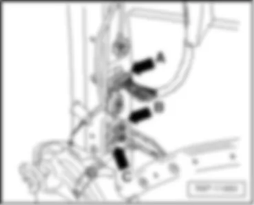
T17k 17-pin connector, green, in left A-pillar coupling station


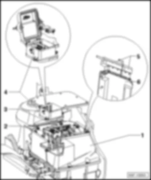
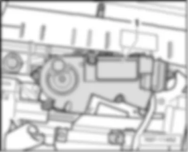
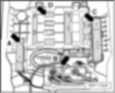
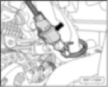
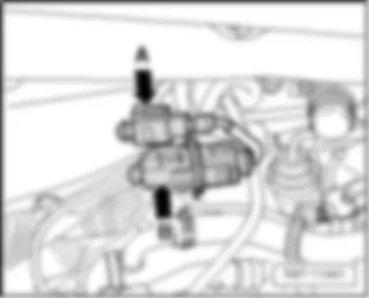
VW TRANSPORTER 2013 engine compartment

engine compartment
VW TRANSPORTER 2013 engine compartment https://portal-diagnostov.com/license.html
https://portal-diagnostov.com/license.html Automotive Electricians Portal FZCO Automotive Electricians Portal FZCO
Obtenez l'accès à tous les schémas de câblage de la voitureDownload PDF file
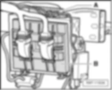
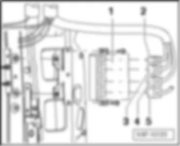
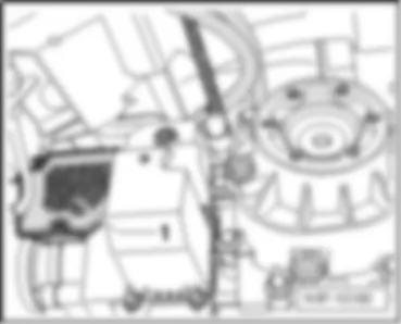
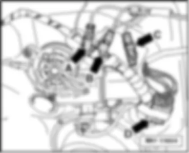
1 -  E-box in engine compartment
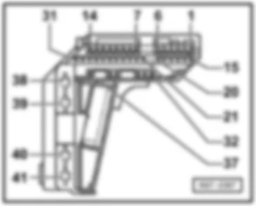
2 -  Fuse holder D -SD- , in engine compartment
3 -  Fuse holder A -SA- , in the E-box
4 -  Top half of the housing for the fuse holder, in engine compart.
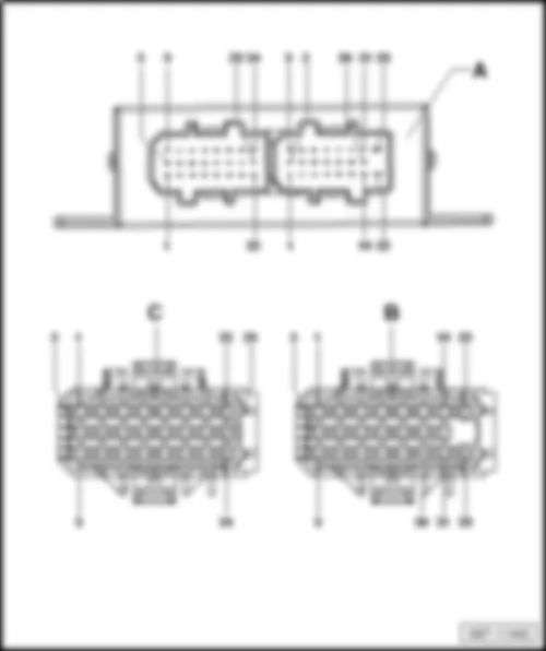
5 -  Connectors on the engine control unit -J623- , in the E-box
6 -  Engine control unit -J623- , in the E-box

–  Back to overview
   
Connector assignment:
VW TRANSPORTER 2013 engine compartment https://portal-diagnostov.com/license.html
https://portal-diagnostov.com/license.html Automotive Electricians Portal FZCO Automotive Electricians Portal FZCO
Obtenez l'accès à tous les schémas de câblage de la voitureDownload PDF file
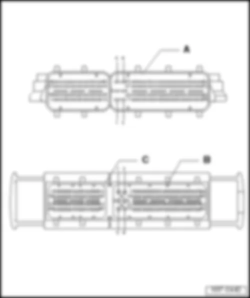
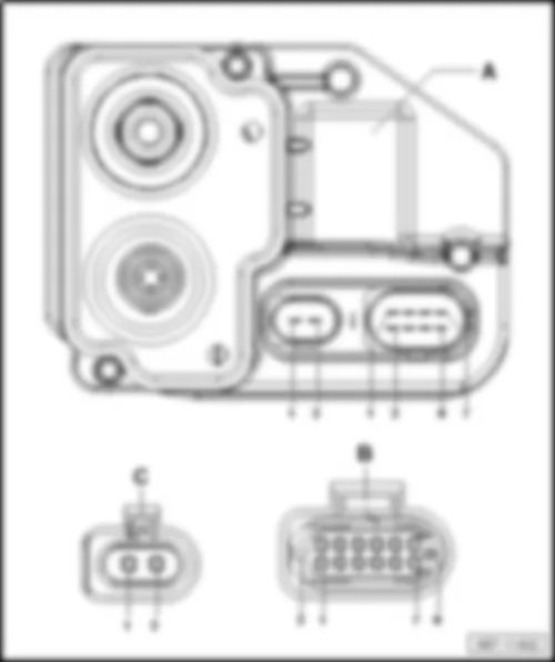
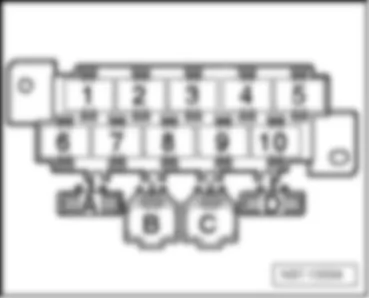
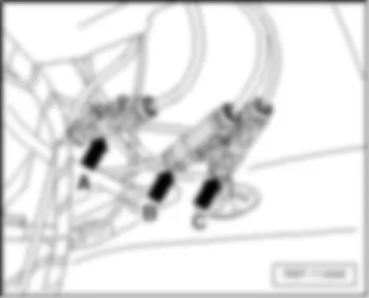
C -  60-pin connector -T60- , black

–  Back to overview
   
Connector assignment:
VW TRANSPORTER 2013 engine compartment https://portal-diagnostov.com/license.html
https://portal-diagnostov.com/license.html Automotive Electricians Portal FZCO Automotive Electricians Portal FZCO
Obtenez l'accès à tous les schémas de câblage de la voitureDownload PDF file
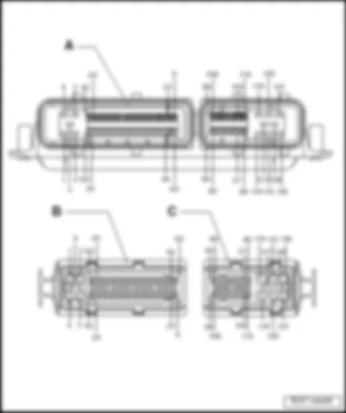
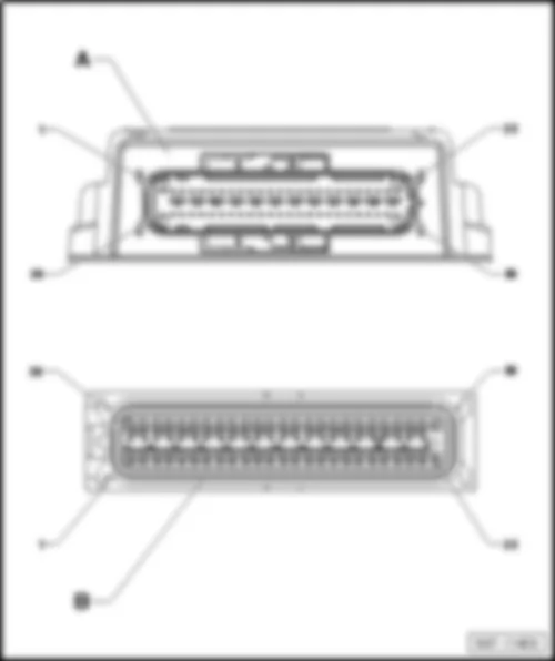
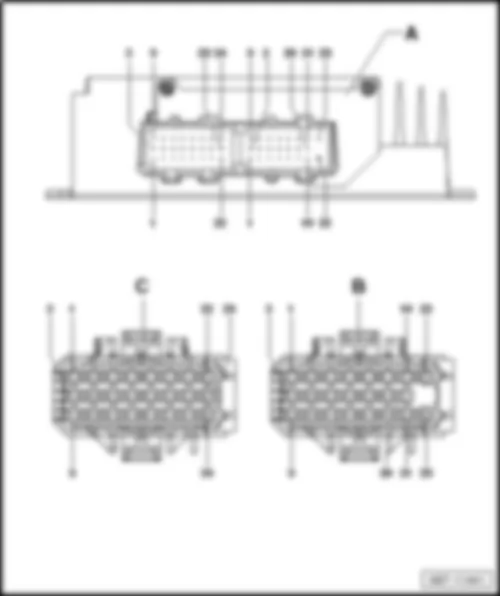
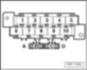
A -  Engine control unit -J623-
Connector:
B -  81-pin connector -T121- , black
C -  40-pin connector -T121- , black

  Note
The 40-pin connector -T40- and the 81-pin connector -T81- are represented in the wiring diagram as a 121-pin connector -T121- .
–  Back to overview


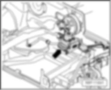
VW TRANSPORTER 2013 ABS control unit J104

ABS control unit -J104-
Fitting location:
on left in engine compartment
 
VW TRANSPORTER 2013 ABS control unit J104 https://portal-diagnostov.com/license.html
https://portal-diagnostov.com/license.html Automotive Electricians Portal FZCO Automotive Electricians Portal FZCO
Obtenez l'accès à tous les schémas de câblage de la voitureDownload PDF file
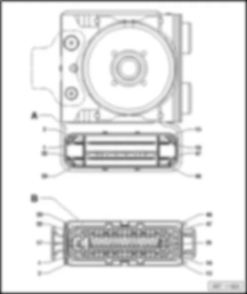
Connector assignment of ABS control unit -J104-
VW TRANSPORTER 2013 ABS control unit J104 https://portal-diagnostov.com/license.html
https://portal-diagnostov.com/license.html Automotive Electricians Portal FZCO Automotive Electricians Portal FZCO
Obtenez l'accès à tous les schémas de câblage de la voitureDownload PDF file

–  Back to overview


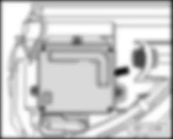
VW TRANSPORTER 2013 Voltage stabiliser J532

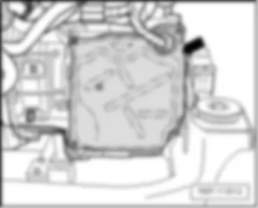
Voltage stabiliser -J532-
Fitting location:
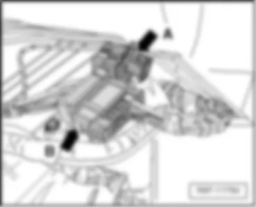
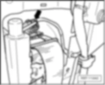
E-box in engine compartment -arrow-
–  Back to overview
 
VW TRANSPORTER 2013 Voltage stabiliser J532 https://portal-diagnostov.com/license.html
https://portal-diagnostov.com/license.html Automotive Electricians Portal FZCO Automotive Electricians Portal FZCO
Obtenez l'accès à tous les schémas de câblage de la voitureDownload PDF file


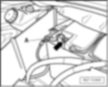
VW TRANSPORTER 2013 Battery monitoring control unit J367

Battery monitoring control unit -J367-
Fitting location:
on the battery in​ engine​ compart., left -A-
–  Back to overview


VW TRANSPORTER 2013 Mechatronic unit for dual clutch gearbox J743

Mechatronic unit for dual clutch gearbox -J743-
 
VW TRANSPORTER 2013 Mechatronic unit for dual clutch gearbox J743 https://portal-diagnostov.com/license.html
https://portal-diagnostov.com/license.html Automotive Electricians Portal FZCO Automotive Electricians Portal FZCO
Obtenez l'accès à tous les schémas de câblage de la voitureDownload PDF file
Fitting location:
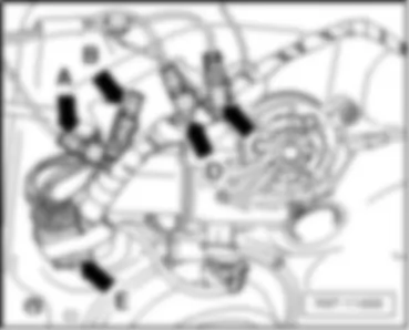
directly on the gearbox -arrow-
–  Back to overview
 
VW TRANSPORTER 2013 Mechatronic unit for dual clutch gearbox J743 https://portal-diagnostov.com/license.html
https://portal-diagnostov.com/license.html Automotive Electricians Portal FZCO Automotive Electricians Portal FZCO
Obtenez l'accès à tous les schémas de câblage de la voitureDownload PDF file
Connector assignment of mechatronic unit for dual clutch gearbox -J743-
VW TRANSPORTER 2013 Mechatronic unit for dual clutch gearbox J743 https://portal-diagnostov.com/license.html
https://portal-diagnostov.com/license.html Automotive Electricians Portal FZCO Automotive Electricians Portal FZCO
Obtenez l'accès à tous les schémas de câblage de la voitureDownload PDF file
c -  2-pin connector -T2-

–  Back to overview


VW TRANSPORTER 2013 Radiator fan control unit J293

Radiator fan control unit -J293-
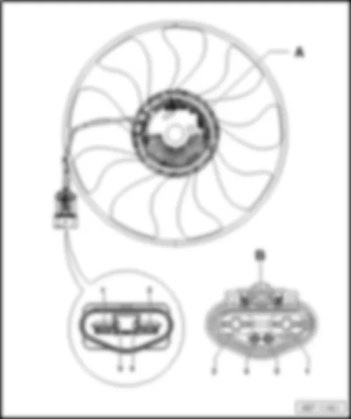
Radiator fan control unit -J293- with higher fan power
VW TRANSPORTER 2013 Radiator fan control unit J293 https://portal-diagnostov.com/license.html
https://portal-diagnostov.com/license.html Automotive Electricians Portal FZCO Automotive Electricians Portal FZCO
Obtenez l'accès à tous les schémas de câblage de la voitureDownload PDF file
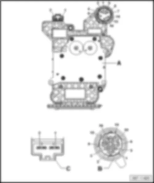
A -  Radiator fan control unit -J293-
  Note
Only models with higher fan power
Connector:
B -  4-pin connector -T4ax- , black

–  Back to overview
   
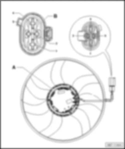
Radiator fan control unit -J293- with low or medium fan power
VW TRANSPORTER 2013 Radiator fan control unit J293 https://portal-diagnostov.com/license.html
https://portal-diagnostov.com/license.html Automotive Electricians Portal FZCO Automotive Electricians Portal FZCO
Obtenez l'accès à tous les schémas de câblage de la voitureDownload PDF file
A -  Radiator fan control unit -J293-
  Note
Only models with low or medium fan power
Connector:
B -  4-pin connector -T4ak- , black

–  Back to overview
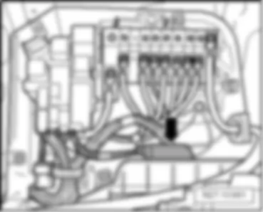
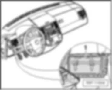
Onboard supply control unit -J519-
   
Fitting location:
under the dash panel -arrow-
 
VW TRANSPORTER 2013 Radiator fan control unit J293 https://portal-diagnostov.com/license.html
https://portal-diagnostov.com/license.html Automotive Electricians Portal FZCO Automotive Electricians Portal FZCO
Obtenez l'accès à tous les schémas de câblage de la voitureDownload PDF file
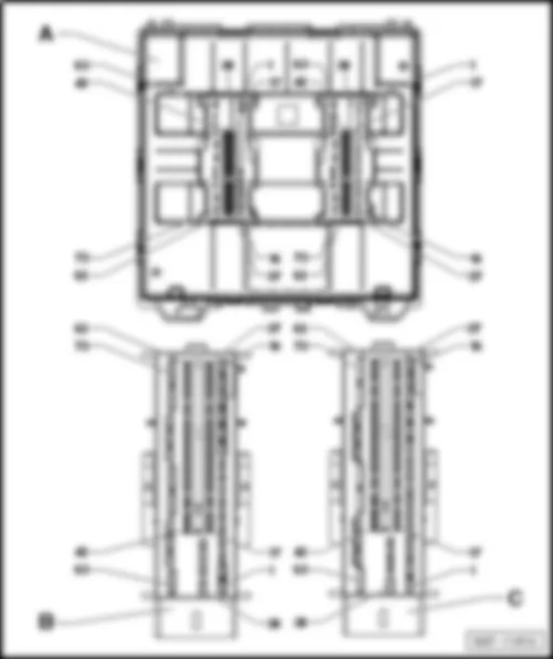
Onboard supply control unit -J519-
VW TRANSPORTER 2013 Radiator fan control unit J293 https://portal-diagnostov.com/license.html
https://portal-diagnostov.com/license.html Automotive Electricians Portal FZCO Automotive Electricians Portal FZCO
Obtenez l'accès à tous les schémas de câblage de la voitureDownload PDF file
C -  73-pin connector -T73b- , white (only for vehicles without start-stop function).
t  Data bus diagnostic interface -J533- (only for vehicles with start-stop function) 1)
t  Data bus diagnostic interface -J533- (only for vehicles with start-stop function and without special purpose vehicles control unit -J608- ) 2), 3)
t  The Data bus diagnostic interface -J533- is integ. in the onboard supply control unit -J519- (only for vehicles with start-stop function and special purpose vehicles control unit -J608- ).2), 3)
t  The Data bus diagnostic interface -J533- is integ. in the onboard supply control unit -J519- (only for models with start-stop function).4)
t  1) valid until May 2012
t  2) valid after May 2012
t  3) valid until October 2012
t  4) valid after November 2012
–  Back to overview
   
Connector assignment of onboard supply control unit -J519-
 
VW TRANSPORTER 2013 Radiator fan control unit J293 https://portal-diagnostov.com/license.html
https://portal-diagnostov.com/license.html Automotive Electricians Portal FZCO Automotive Electricians Portal FZCO
Obtenez l'accès à tous les schémas de câblage de la voitureDownload PDF file
73-pin connector -T73a-
Pin   Assignment/Component Input/Output Terminal
1 -
-
-
Relay for headlight main beam -J12-9), 14), 16)
Fuse 1 on fuse holder F -SF1-4), 9), 14), 16)
Fuse 12 on fuse holder F -SF12-4), 9), 14), 16)
Output 56b
-
-
-
-
-
Control unit in dash panel insert -J285-9), 14), 17)
Fuse 4 on fuse holder F -SF4-4), 9), 14), 17)
2-filament bulb for right headlight -L2-14), 17)
Auxiliary right main beam bulb -M68-9), 17)
Blind for right low beam -V295-9), 17)
Output 56a
2 -
-
-
2-filament light bulb for left headlight -L1-14)
Left headlight dipped beam bulb -M29-14)
Left gas discharge bulb control unit -J343-9)
t  Left gas discharge bulb -L13-9)
Output 56b
3 -
-
-
Battery isolator relay -J7-
Second battery charging circuit relay -J713-
Operating and display unit for camping equipment -E153-
Output 85
4 -
-
-
-
-
-
-
-
-
Front interior light -W1-
Interior lighting central switch-off button -E390-
Taxi interior light switch -E115-10), 13)
Interior monitoring switch -E183-
Button to deactivate interior monitor and vehicle inclination sensor -E616-
3-pin connector -T3am-
3-pin connector -T3an-
Rear interior lights
Illuminated sill panel trim
Output 31
5 -
-
-
2-filament light bulb for right headlight -L2-14)
Right daytime running light bulb -L175-14)
Control unit for right daytime running light and side light -J861-9)
t  Right LED module for daytime running light and side light -L177-9)
Output DRL
6 -
-
-
-
Rear left fog light bulb -L46-
Rear right fog light bulb -L47-
Bulb for left tail light and rear fog light -M41-
Bulb for right tail light and rear fog light -M42-
Output NSL
7 -
-
-
Switch for front and rear fog lights -E23- (T10bb/5)
Switch for front and rear fog lights -E23- (T17/8)
t  Fuse 5 on fuse holder F -SF5-4)
Input NSW
8 -
Isolation relay for powertrain CAN bus -J788- Output 85
9 -
Not assigned - -
10 - Rear lid release motor -V139-2) Output -
11 -
-
-
-
-
-
-
Contact strip in right sliding door -F352-2)
Contact strip in left sliding door -F353-2)
Driver door central locking motor -V56-2)
Front passenger door central locking motor -V57-2)
Rear right door central locking motor -V97-2)
Rear left door central locking motor -V115-2)
Rear lid locking motor -V120-2)
Output -
12 -
Driver door central locking motor -V56- Output -
13 -
Not assigned - -
14 -
Earth for central locking Input 31
15 -
-
-
-
-
-
Contact strip in right sliding door -F352-2)
Contact strip in left sliding door -F353-2)
Front passenger door central locking motor -V57-2)
Rear right door central locking motor -V97-2)
Rear left door central locking motor -V115-2)
Rear lid locking motor -V120-2)
Output -
16 -
Fuse 8 on fuse holder B -SB8- (Terminal 30 central locking)
t  Alarm horn -H12-
t  Left sliding door control unit -J558-
t  Rear lid control unit -J605-
t  Right sliding door control unit -J731-
Input 30
17 -
-
Contact strip in left sliding door -F353-2)
Rear left central locking lock unit -F222-2), 7)
Input -
18 -
-
Contact strip in right sliding door -F352-2)
Rear right central locking lock unit -F223-2), 7)
Input -
19 -
-
Driver door contact switch -F2-
Driver side central locking lock unit -F220-
Input -
20 -
-
Front passenger door contact switch -F3-
Front passenger side central locking lock unit -F221-
Input -
21 -
Front passenger side central locking lock unit -F221- Input -
22 -
Driver side central locking lock unit -F220- Input -
23 -
-
-
Rear lid handle release button -E234-
Childproof lock button -E318-
Release button for rear lid lock cylinder -F248-
Input -
24 -
Driver side central locking lock unit -F220- Input -
25 -
Switch for driver side interior locking -E150- Input -
26 -
-
-
-
Right sliding door control unit -J731-
Double inverter relay -J741-
Rear right door contact switch -F11-
Rear right central locking lock unit -F223-7)
Input -
27 -
Bonnet contact switch -F266- Input -
28 -
Hazard warning light switch -E3- Input -
29 -
Steering column combination switch -E595-
t  Coil connector -F350-
t  Horn plate -H-
Input -
30 -
Contact switch in rear lid -F111-
t  Rear lid control unit -J605-
Input -
31 -
Luggage compartment light switch -F5-
t  Centre interior light -W7-
t  Rear left reading light -W11-
t  Rear right reading light -W12-
t  Luggage compartment light on left -W18-
t  Right luggage compartment light -W35-
Input -
32 -
Steering column combination switch -E595-
t  Turn signal switch -E2-
t  10-pin connector -T10bj-4)
Input R
33 -
Steering column combination switch -E595-
t  Turn signal switch -E2-
t  10-pin connector -T10bj-4)
Input L
34 -
-
-
-
Left sliding door control unit -J558-
Double inverter relay -J741-
Rear left door contact switch -F10-
Rear left central locking lock unit -F222-7)
Input -
35 -
Sliding sunroof adjustment control unit -J245- Output -
36 -
Heated front seats control unit -J774- Output Authorisation
37 -
Light switch -E1- (T10bb/2) Input AFL
38 -
-
-
Suppression filter -C10-
Heated exterior mirror on driver side -Z4-
Heated exterior mirror on front passenger side -Z5-
Output -
39 -
Not assigned - -
40 -
-
-
-
Right tail light bulb -M2-7)
Right side light bulb -M3-
Right brake and tail light bulb -M22-
Bulb for right tail light and rear fog light -M42-
Output 58R
41 -
-
-
-
-
-
Left side light bulb -M1-
Left tail light bulb -M4-7)
Left brake and tail light bulb -M21-
Bulb for left tail light and rear fog light -M41-
6-pin connector -T6bn-
10-pin connector -T10bh-4)
Output 58L
42 -
Fuse 19 on fuse holder B -SB19-
t  Operating and display unit for camping equipment -E153-
t  Roof hydraulics control unit -J768-
t  10-pin connector -T10bh-4)
t  10-pin connector -T10bj-4)
Input 86s
43 -
Brake light switch -F-
t  ABS control unit -J104-
t  Trailer detector control unit -J345-
t  Engine control unit -J623-
Input 54
44 -
Fuse 16 on fuse holder B -SB16-
t  Start/Stop operation button -E693-11)
t  Voltage stabiliser -J532-11)
t  Data bus diagnostic interface -J533-11)
Input 15
45 -
-
Light switch -E1- (T10bb/3)
Light switch -E1- (T17/16)
t  Regulator for switch and instrument illumination -E20-
t  Fuse 11 on fuse holder B -SB11-
t  Fuse 35 on fuse holder B -SB35-
Input 58
46 -
Not assigned - -
47 -
Not assigned - -
48 -
Sliding sunroof adjustment control unit -J245- Output -
49 -
Headlight washer system relay -J39- Output -
50 -
Not assigned Output -
51 -
Entry and footwell light relay -J348- Output -
52 -
Electric fuel pump 2 relay -J49- Output -
53 -
Not assigned -
54 -
X-contact relief relay -J59- Output 75X
55 -
-
-
Engine control unit -J623-
Starter inhibitor relay -J207-
10-pin connector -T10bj-4)
Output 50
56 -
Hazard warning light switch -E3- Output -
57 -
-
Interior monitoring switch -E183-
Button to deactivate interior monitor and vehicle inclination sensor -E616-
Output -
58 -
Central locking SAFE function warning lamp -K133- Output -
59 -
Not assigned - -
60 -
Heated rear window switch -E15- Output -
61 -
Not assigned - -
62 -
Headlight dipper and flasher switch -E4- (T41/39) 9), 14), 16)
t  Control unit for alarm system -J85-9), 10), 14), 16)
t  Control unit in dash panel insert -J285-9), 14), 16)
t  Front left headlight -MX1-9), 14), 16)
t  Front right headlight -MX2-9), 14), 16)
t  Fuse 6 on fuse holder B -SB6-9), 14), 16)
t  Fuse 28 on fuse holder B -SB28-9), 14), 16)
t  Fuse 3 on fuse holder F -SF3-4), 9), 14), 16)
t  Fuse 4 on fuse holder F -SF4-4), 9), 14), 16)
Input 56a
-
Headlight dipper and flasher switch -E4- (T41/40) 9), 14), 17) Input 56b
63 -
Fuse 12 on fuse holder C -SC12-9), 14)
t  Left low beam 9), 14)
t  Right main beam 9), 14), 17)
t  Left reversing light bulb -M16-9), 14), 15)
t  Right reversing light bulb -M17-9), 14), 15),
Input 30
64 -
Fuse 20 on fuse holder C -SC20-
t  Heated exterior mirror on driver side -Z4-
t  Heated exterior mirror on front passenger side -Z5-
Input 30
65 -
-
Fuse 17 on fuse holder C -SC17- 3)
Fuse 24 on fuse holder C -SC24- 3)
t  Front and rear interior lights
t  Luggage compartment lights -W18- , -W35-
t  illuminated sill panel trim -W31- , -W32- , -W33- , -W34-
t  Glove compartment light -W6-
t  illuminated vanity mirrors -W14- , -W20-
t  Automatic anti-dazzle interior mirror -Y7-
Output 30G
66 -
-
Fuse 7 on fuse holder B -SB7- 3)
Fuse 17 on fuse holder C -SC17- 3)
t  Side light (terminal 58L/58R)
t  Front and rear interior lights (terminal 30G)
t  Luggage compartment lights -W18- , -W35-
t  illuminated sill panel trim -W31- , -W32- , -W33- , -W34-
t  Glove compartment light -W6-
t  illuminated vanity mirrors -W14- , -W20-
t  Automatic anti-dazzle interior mirror -Y7-
Input 30
67 -
Not assigned - -
68 -
Fuse 32 on fuse holder B -SB32-
t  Windscreen wiper motor -V-
Input 30
69 -
Windscreen wiper motor -V- Output Stage 1
70 -
Earth for windscreen wiper motor -V- Input 31
71 -
Windscreen wiper motor -V- Output Stage 2
72 -
-
-
-
Horn and dual tone horn -H1-
Bass horn -H7-
Horn relay -J413-
10-pin connector -T10bj-4)
Output Horn
73 -
Fuse 31 on fuse holder B -SB31-
t  Horn and dual tone horn -H1-
t  Bass horn -H7-
Input 30

  Note
t  1) Only for vehicles with dual clutch gearbox
t  2) Only for vehicles with central locking
t  3) See wiring diagram for interior lights
t  4) Only for vehicles with interface for external use
t  5) Only for vehicles without central locking
t  6) Only for vehicles with mechanically operated sliding door and without anti-theft alarm
t  7) Only for vehicles with double cab/platform
t  8) Only for vehicles with anti-theft alarm (ATA) and signal horn for anti-theft alarm
t  9) Only for vehicles with with gas pressure bulb headlights
t  10) Only for vehicles with taxi equipment
t  11) Only for vehicles with start-stop system
t  12) valid until November 2009
t  13) valid until May 2012
t  14) Only for vehicles with automatic headlight switching
t  15) Valid from November 2012
t  16) valid until May 2014
t  17) Valid from May 2014
–  Back to overview
   
73-pin connector -T73b-
Pin   Assignment/Component Input/Output Terminal
1 -
-
-
Switch and instrument illumination regulator -E20-9), 13), 15), 16)
Fuse 35 on fuse holder B -SB35-9), 13), 15), 16)
Onboard supply control unit -J519- (T73b/34) 9), 13), 15), 16)
Output 58
  -
-
-
Switch and instrument illumination regulator -E20-9), 16), 17)
Fuse 35 on fuse holder B -SB35-9), 16), 17
Onboard supply control unit -J519- (T73b/34) 9), 16), 17)
Output 58
  -
-
-
-
2-filament light bulb for left headlight -L1-16), 21)
Fuse 3 on fuse holder F -SF3-4), 9), 16), 21)
Auxiliary left main beam bulb -M67-9), 21)
Blind for left low beam -V294-9), 21)
Output 56a
2 -
-
-
-
Right headlight dipped beam bulb -M31-16)
2-filament light bulb for right headlight -L2-16)
Fuse 1 on fuse holder F -SF1-9), 16)
Control unit for right gas-discharge lamp -J344-9)
t  Right gas discharge bulb -L14-9)
Output 56b
3 -
-
-
2-filament light bulb for left headlight -L1-16)
Left daytime running light bulb -L174-16)
Control unit for left daytime running light and side light -J860-9)
t  Left LED module for daytime running light and side -L176-9)
Output DRL
4   Not assigned 13) - -
  -
-
-
Switch and instrument illumination regulator -E20-9), 14), 15), 16)
Fuse 35 on fuse holder B -SB35-9), 14), 15), 16)
Onboard supply control unit -J519- (T73b/34) 9), 14), 15), 16)
Output 58d
  -
-
-
Switch and instrument illumination regulator -E20-9), 16), 18)
Fuse 35 on fuse holder B -SB35-9), 16), 18)
Onboard supply control unit -J519- (T73b/34) 9), 16), 18)
Output 58d
5 - Control unit for left daytime running light and side light -J860-9)
t  Left LED module for daytime running light and side -L176-9)
Output 58L
6 - Control unit for right daytime running light and side light -J861-9)
t  Right LED module for daytime running light and side light -L177-9)
Output 58R
7 -
-
-
Licence plate light -X-9), 16)
Left license plate light -X4-7), 9), 16)
Right license plate light -X5-7), 9), 16)
Output 58
8 - Not assigned 20) - -
- Headlight dipper and flasher switch -E4- (T41/39) 9), 16), 21) Input 56a
9 -
-
Left fog light bulb -L22-
Fuse 5 on fuse holder F -SF5-4)
Output NSW
10 - Right fog light bulb -L23- Output NSW
11 - Fuse 35 on fuse holder C -SC35-
t  Left reversing light bulb -M16-17)
t  Right reversing light bulb -M17-17)
t  Left fog light bulb -L22- (Cornering light)
t  Right fog light bulb -L23- (Cornering light)
Input 30
12 -
-
-
-
-
Accident data memory -J754-
Reversing light bulb -M16- , -M17-
10-pin connector -T10bh-4)
Trailer socket -U10-
Automatic anti-dazzle interior mirror -Y7-
Output RFL
13 - Fuse 36 on fuse holder B -SB36-
t  Brake light (terminal 54)
t  Turn signal (terminal 49)
Input 30
14 -
-
-
-
-
-
Accident data memory -J754-
Blocking diode -J29-10), 13)
Front left turn signal bulb -M5-
Rear left turn signal bulb -M6-
Left turn signal repeater bulb -M18-
Left roof mounted turn signal bulb -M23-
Output 49L
15 -
-
-
-
-
-
Accident data memory -J754-
Blocking diode -J29-10), 13)
Front right turn signal bulb -M7-
Rear right turn signal bulb -M8-
Right turn signal repeater bulb -M19-
Right roof mounted turn signal bulb -M24-
Output 49R
16 -
-
-
-
-
-
-
Accident data memory -J754-
Left brake light bulb -M9-7)
Right brake light bulb -M10-7)
Left brake and tail light bulb -M21-
Right brake and tail light bulb -M22-
High-mounted brake light bulb -M25-
6-pin connector -T6bn-4)
Output 54
17 -
-
-
Driver door control unit -J386-
Front passenger door control unit -J387-
Steering column combination switch -E595-
t  Coil connector -F350-
t  Multifunction steering wheel control unit -J453-
Input/Output LIN
18 - B390 Connection 1 (powertrain CAN bus, low), in main wiring harness Input/Output CAN Low
19 - B383 Connection 1 (powertrain CAN bus, high), in main wiring harness Input/Output CAN High
20 - B397 Connection 1 (convenience CAN bus, high), in main wiring harness Input/Output CAN High
21 - B406 Connection 1 (convenience CAN bus, low), in main wiring harness Input/Output CAN Low
22 -
-
16-pin connector -T16/14- (Diagnostics port)
Data bus diagnostic interface -J533- (T20f/9) 11)
Input/Output CAN Low
23 -
-
16-pin connector -T16/6- (Diagnostics port)
Data bus diagnostic interface -J533- (T20f/19) 11)
Input/Output CAN High
24 -
-
-
Interior monitor send and receive module 1 -G303 -
Vehicle inclination sender -G384-
Rain and light sensor -G397-
Input/Output LIN
25 - Contact strip in left sliding door -F353-2)
t  Rear left central locking lock unit -F222-2)
Input -
26 -
Contact strip in right sliding door -F352-2)
t  Rear right central locking lock unit -F223-2)
Input -
27 - Steering column combination switch -E595-
t  Intermittent wiper switch -E22-
Input Stage 1
28 - Not assigned - -
29 - Light switch -E1- (T10bb/9) Input DRL
30 -
-
Interior monitoring switch -E183-
Button to deactivate interior monitor and vehicle inclination sensor -E616-
Input -
31 - Heated rear window switch -E15- Input -
32 - Windscreen wiper motor -V- Input 53a
33 -
Not assigned -
34 -
-
-
Switch and instrument illumination regulator -E20-
Fuse 35 on fuse holder B -SB35-
Onboard supply control unit -J519- (T73b/1)
Input 58d
35 - Not assigned - -
36 - Alarm horn -H12-8) - LIN
37 - Diagnostic connection -U31-13)
t  16-pin connector -T16/7-
t  Auxiliary air heater control unit -J604-
t  Engine control unit -J623-
- K
- Alternator -C-11), 14), 15) Input/Output LIN
38 - Ground (internal supply) Input 31
39 - Fuse 3 on fuse holder B -SB3- (internal supply) Input 30
40 - Not assigned - -
41 - Not assigned - -
42 - Not assigned - -
43 -
-
Rear fog light switch -E18- (T10bb/7)
Switch for front and rear fog lights -E23- (T10bb/7)
Input NSL
44 - Steering column combination switch -E595-
t  CCS SET button -E227-
Input -
45 - Steering column combination switch -E595-
t  CCS switch -E45-
t  Engine control unit -J623-
Input -
46 - Steering column combination switch -E595-
t  CCS SET button -E227-
Input -
47 - Steering column combination switch -E595-
t  CCS switch -E45-
Input -
48 - Reversing light switch -F4-
t  Accident data memory -J754-
t  Reversing light bulb -M16- , -M17-
t  10-pin connector -T10bh-4)
t  Trailer socket -U10-
t  Automatic anti-dazzle interior mirror -Y7-
Input RFL
49 - Alternator -C-19)
t  Engine control unit -J623-19)
Input 61
50 -
-
-
-
-
Blocking diode -J29-12)
Starter inhibitor relay -J433-
Voltage stabiliser -J532-11)
Engine control unit -J623-
Ignition/starter switch -D-
t  X-contact relief relay -J59-
t  Fuse 21 on fuse holder B -SB21-
t  Fuse 23 on fuse holder B -SB23-
Input 50
51 -
-
Ignition/starter switch -D-
X-contact relief relay -J59-
t  Horn relay -J413-
t  Terminal 75 voltage supply relay 1 -J680-
t  Fuse 5 on fuse holder C -SC5-4)
t  12-pin connector -T12y-
Input 75X
52 - Light switch -E1- (T10bb/1) Input FL
  - Light switch -E1- (T17/11) Input HWS
53 - Steering column combination switch -E595-
t  Intermittent wiper switch -E22-
Input Stage 2
54 - Not assigned 13) - -
  - B708 Connection 1 (dash panel insert CAN bus high) in main wiring harness 11), 14), 15), 16), 17) Input/Output CAN High
  - B708 Connection 1 (dash panel insert CAN bus high) in main wiring harness 11), 18) Input/Output CAN High
55 - Mechatronic unit for dual clutch gearbox -J743-1) Input 50
56 - Rear lid lock unit -F256- Input -
57 - Not assigned 13) - -
  - B709 Connection 1 (dash panel insert CAN bus low) in main wiring harness 11), 14), 15), 16), 17) Input/Output CAN Low
  - B709 Connection 1 (dash panel insert CAN bus low) in main wiring harness 11), 18) Input/Output CAN Low
58 -
Exterior mirror heater button -E231- Input -
59 -
Fuse 34 on fuse holder D -SD34- (Reference battery voltage) Input 30
60 - Reference battery voltage Input 31
61 -
Steering column combination switch -E595-
t  Rear window wiper switch -E34-
t  Washer pump switch (automatic wash/wipe and headlight washer system) -E44-
t  Fuse 7 on fuse holder D -SD7-
t  Washer pump -V5-
t  Rear window wiper motor -V12-
t  Windscreen and rear window washer pump -V59-
t  Rear left wing door window wiper motor -V92-
Input -
62 -
Steering column combination switch -E595-
t  Intermittent wiper switch -E22-
t  Intermittent wiper regulator -E38-
Input INT
63 -
-
-
heated rear window -Z1-
Heated rear window in left wing door -Z26-
Heated rear window in right wing door -Z27-
Output -
64 - Not assigned - -
65 - Not assigned - -
66 - Not assigned - -
67 -
Fuse 9 on fuse holder B -SB9-
t  heated rear window -Z1-
t  Heated rear window in left wing door -Z26-
t  Heated rear window in right wing door -Z27-
Input 30
68 -
Fuse 14 on fuse holder C -SC14-9), 16)
t  Right low beam 9), 16)
t  Left main beam 9), 16), 21)
Input 30
69 - Not assigned - -
70 - Not assigned - -
71 - Not assigned - -
72 - Not assigned - -
73 - Not assigned - -

  Note
t  1) For models with dual clutch gearbox only
t  2) For models with central locking only
t  3) See wiring diagram for interior lights
t  4) For models with interface for external use only
t  5) For models without central locking only
t  6) For models with mechanically operated sliding door and without anti-theft alarm only
t  7) For models with double cab/platform only
t  8) For models with anti-theft alarm (ATA) and signal horn for anti-theft alarm only
t  9) For models with gas pressure bulb headlights only
t  10) For models with taxi equipment only
t  11) For models with start-stop system only
t  12) Valid until November 2009
t  13) Valid until May 2012
t  14) Valid from May 2012
t  15) For models with special purpose vehicles control unit only -J608-
t  16) only for vehicles with automatic main beam switching
t  17) valid until October 2012
t  18) valid from November 2012
t  19) only for vehicles without start-stop system
t  20) valid until May 2014
t  21) valid from May 2014
–  Back to overview


VW TRANSPORTER 2013 Control unit in dash panel insert J285

Control unit in dash panel insert -J285-
VW TRANSPORTER 2013 Control unit in dash panel insert J285 https://portal-diagnostov.com/license.html
https://portal-diagnostov.com/license.html Automotive Electricians Portal FZCO Automotive Electricians Portal FZCO
Obtenez l'accès à tous les schémas de câblage de la voitureDownload PDF file
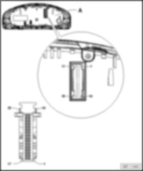
A -  Control unit in dash panel insert -J285-
 -  32-pin connector -T32- , blue

  Note
The immobiliser control unit -J362- is integrated in the control unit in the dash panel insert -J285- .
   
32-pin connector -T32-
VW TRANSPORTER 2013 Control unit in dash panel insert J285 https://portal-diagnostov.com/license.html
https://portal-diagnostov.com/license.html Automotive Electricians Portal FZCO Automotive Electricians Portal FZCO
Obtenez l'accès à tous les schémas de câblage de la voitureDownload PDF file
1 -  Fuel gauge sender (full)
2 -  Fuel gauge sender (empty)
3 -  Not assigned
4 -  Not assigned
5 -  Not assigned
6 -  Not assigned
7 -  Immobiliser reader coil -D2- (1)
8 -  Immobiliser reader coil -D2- (2)
9 -  Speedometer signal, output
10 -  Not assigned
11 -  Oil level and oil temperature sender -G266-
12 -  Not assigned
13 -  Rear fog light warning lamp
14 -  Main beam warning lamp
15 -  Front left brake pad wear sender -G34- /Sensor for rear right brake pad wear -G37-
16 -  Terminal 31
17 -  Windscreen washer fluid level sender -G33-
18 -  Coolant shortage indicator sender -G32-
19 -  Ambient temperature sensor -G17-
20 -  Terminal 31, sensor earth
21 -  Multifunction display call-up button -E86- (MFA+)
22 -  Multifunction display call-up button -E86- (MFA-)
23 -  Multifunction display memory switch -E109- (MFA-R)
24 -  Not assigned
25 -  Handbrake warning switch -F9-
26 -  Brake fluid level warning contact -F34-
27 -  Oil pressure switch -F1-
28 -  Diagnostic interface for dash panel insert CAN data bus, high
29 -  Diagnostic interface for dash panel insert CAN data bus, low
30 -  Not assigned
31 -  Voltage supply, terminal 15
32 -  Voltage supply, terminal 30

–  Back to overview


VW TRANSPORTER 2013 Parking aid control unit J446

Parking aid control unit -J446-
   
Fitting location:
Left behind the dash panel -arrow A-
 
VW TRANSPORTER 2013 Parking aid control unit J446 https://portal-diagnostov.com/license.html
https://portal-diagnostov.com/license.html Automotive Electricians Portal FZCO Automotive Electricians Portal FZCO
Obtenez l'accès à tous les schémas de câblage de la voitureDownload PDF file
Connector assignment of parking aid control unit -J446-
VW TRANSPORTER 2013 Parking aid control unit J446 https://portal-diagnostov.com/license.html
https://portal-diagnostov.com/license.html Automotive Electricians Portal FZCO Automotive Electricians Portal FZCO
Obtenez l'accès à tous les schémas de câblage de la voitureDownload PDF file
C -  12-pin connector -T12r- , brown

–  Back to overview


VW TRANSPORTER 2013

Driver door control unit -J386- /Front passenger door control unit -J387-
   
Fitting location:
In the front left door -Position A-
  Note
The illustration shows the right side. The left side is similar.
 
VW TRANSPORTER 2013 https://portal-diagnostov.com/license.html
https://portal-diagnostov.com/license.html Automotive Electricians Portal FZCO Automotive Electricians Portal FZCO
Obtenez l'accès à tous les schémas de câblage de la voitureDownload PDF file
Connector assignment of driver door control unit -J386- /Front passenger door control unit -J387-
VW TRANSPORTER 2013 https://portal-diagnostov.com/license.html
https://portal-diagnostov.com/license.html Automotive Electricians Portal FZCO Automotive Electricians Portal FZCO
Obtenez l'accès à tous les schémas de câblage de la voitureDownload PDF file
A -  Driver door control unit -J386- /Front passenger door control unit -J387-
B -  16-pin connector -T16k- , black/16-pin connector -T16l- , black

  Note
The illustration shows the right side. The left side is similar.
–  Back to overview


VW TRANSPORTER 2013 Airbag control unit J234

Airbag control unit -J234-
   
Fitting location:
Central under the dash panel -arrow-
 
VW TRANSPORTER 2013 Airbag control unit J234 https://portal-diagnostov.com/license.html
https://portal-diagnostov.com/license.html Automotive Electricians Portal FZCO Automotive Electricians Portal FZCO
Obtenez l'accès à tous les schémas de câblage de la voitureDownload PDF file
Connector assignment of airbag control unit -J234-
VW TRANSPORTER 2013 Airbag control unit J234 https://portal-diagnostov.com/license.html
https://portal-diagnostov.com/license.html Automotive Electricians Portal FZCO Automotive Electricians Portal FZCO
Obtenez l'accès à tous les schémas de câblage de la voitureDownload PDF file

–  Back to overview


VW TRANSPORTER 2013

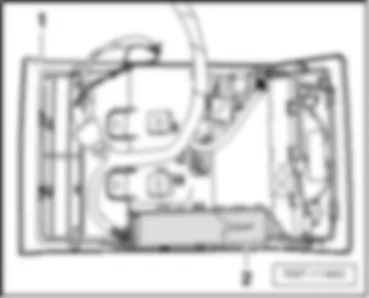
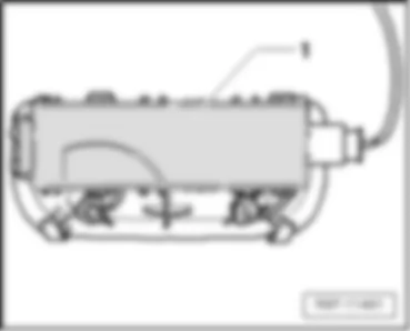
Interior monitor send and receive module 1 -G303- with control unit for inclination protection and theft protection -J529-
Fitting location:
on the roof console -position 2-
Roof console -position 1-
–  Back to overview
 
VW TRANSPORTER 2013 https://portal-diagnostov.com/license.html
https://portal-diagnostov.com/license.html Automotive Electricians Portal FZCO Automotive Electricians Portal FZCO
Obtenez l'accès à tous les schémas de câblage de la voitureDownload PDF file


VW TRANSPORTER 2013 Interior monitor send and receive module 2 G305

Interior monitor send and receive module 2 -G305-
Fitting location:
in rear headliner -position 1-
–  Back to overview
 
VW TRANSPORTER 2013 Interior monitor send and receive module 2 G305 https://portal-diagnostov.com/license.html
https://portal-diagnostov.com/license.html Automotive Electricians Portal FZCO Automotive Electricians Portal FZCO
Obtenez l'accès à tous les schémas de câblage de la voitureDownload PDF file


VW TRANSPORTER 2013 Heated front seats control unit J774

Heated front seats control unit -J774-
Fitting locations:
behind dash panel, near relay carrier cockpit -arrow A-
–  Back to overview
 
VW TRANSPORTER 2013 Heated front seats control unit J774 https://portal-diagnostov.com/license.html
https://portal-diagnostov.com/license.html Automotive Electricians Portal FZCO Automotive Electricians Portal FZCO
Obtenez l'accès à tous les schémas de câblage de la voitureDownload PDF file


VW TRANSPORTER 2013 Sliding sunroof adjustment control unit J245

Sliding sunroof adjustment control unit -J245-
Fitting location:
on sliding/tilting sunroof -position 1-
–  Back to overview
 
VW TRANSPORTER 2013 Sliding sunroof adjustment control unit J245 https://portal-diagnostov.com/license.html
https://portal-diagnostov.com/license.html Automotive Electricians Portal FZCO Automotive Electricians Portal FZCO
Obtenez l'accès à tous les schémas de câblage de la voitureDownload PDF file


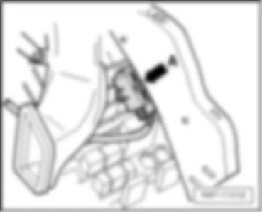
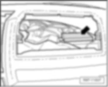
VW TRANSPORTER 2013 Mobile telephone operating electronics control unit J412

Mobile telephone operating electronics control unit -J412-
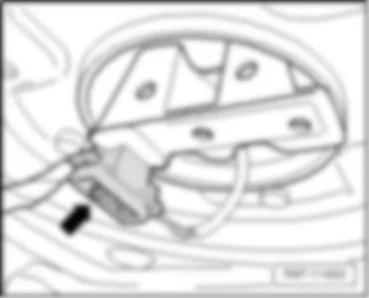
Fitting location:
Behind the glove compartment -arrow-
–  Back to overview
 
VW TRANSPORTER 2013 Mobile telephone operating electronics control unit J412 https://portal-diagnostov.com/license.html
https://portal-diagnostov.com/license.html Automotive Electricians Portal FZCO Automotive Electricians Portal FZCO
Obtenez l'accès à tous les schémas de câblage de la voitureDownload PDF file
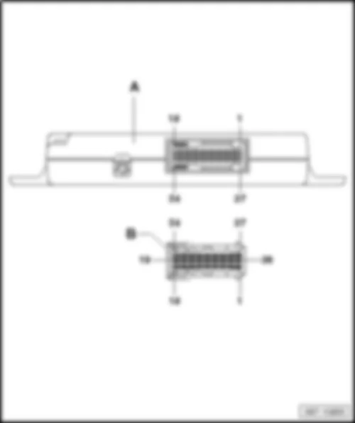
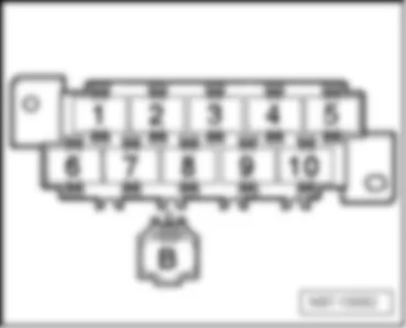
Connector assignment of mobile telephone operating electronics control unit -J412-
VW TRANSPORTER 2013 Mobile telephone operating electronics control unit J412 https://portal-diagnostov.com/license.html
https://portal-diagnostov.com/license.html Automotive Electricians Portal FZCO Automotive Electricians Portal FZCO
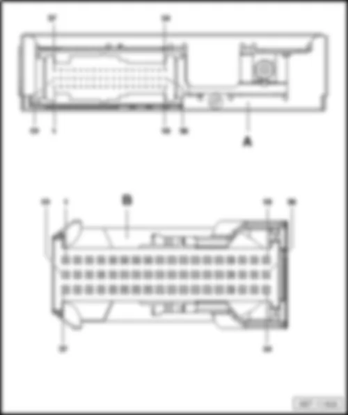
Obtenez l'accès à tous les schémas de câblage de la voitureDownload PDF file
A -  Mobile telephone operating electronics control unit -J412- , black
Connector:
B -  54-pin connector -T54-

–  Back to overview


VW TRANSPORTER 2013 Left sliding door control unit J558

Left sliding door control unit -J558-
Fitting location:
on left D-pillar -position 1-
  Note
Electric sliding door with closing aid
 
VW TRANSPORTER 2013 Left sliding door control unit J558 https://portal-diagnostov.com/license.html
https://portal-diagnostov.com/license.html Automotive Electricians Portal FZCO Automotive Electricians Portal FZCO
Obtenez l'accès à tous les schémas de câblage de la voitureDownload PDF file
Connector assignment of left sliding door control unit -J558-
VW TRANSPORTER 2013 Left sliding door control unit J558 https://portal-diagnostov.com/license.html
https://portal-diagnostov.com/license.html Automotive Electricians Portal FZCO Automotive Electricians Portal FZCO
Obtenez l'accès à tous les schémas de câblage de la voitureDownload PDF file
A -  Left sliding door control unit -J558-
B -  6-pin connector -T6ah- , light brown
D -  12-pin connector -T12k- , black

–  Back to overview
   
Left sliding door control unit -J558-
Fitting location:
on left D-pillar -position A-
  Note
t  Mechanical sliding door with closing aid
t  Illustration shows the right side. The left side is similar.
–  Back to overview
 
VW TRANSPORTER 2013 Left sliding door control unit J558 https://portal-diagnostov.com/license.html
https://portal-diagnostov.com/license.html Automotive Electricians Portal FZCO Automotive Electricians Portal FZCO
Obtenez l'accès à tous les schémas de câblage de la voitureDownload PDF file
Connector assignment of left sliding door control unit -J558-
VW TRANSPORTER 2013 Left sliding door control unit J558 https://portal-diagnostov.com/license.html
https://portal-diagnostov.com/license.html Automotive Electricians Portal FZCO Automotive Electricians Portal FZCO
Obtenez l'accès à tous les schémas de câblage de la voitureDownload PDF file
A -  Left sliding door control unit -J558-
B -  8-pin connector -T8x- , black

–  Back to overview
   
Right sliding door control unit -J731-
Fitting location:
on right D-pillar -position 1-
  Note
Electric sliding door with closing aid
 
VW TRANSPORTER 2013 Left sliding door control unit J558 https://portal-diagnostov.com/license.html
https://portal-diagnostov.com/license.html Automotive Electricians Portal FZCO Automotive Electricians Portal FZCO
Obtenez l'accès à tous les schémas de câblage de la voitureDownload PDF file
Connector assignment of right sliding door control unit -J731-
VW TRANSPORTER 2013 Left sliding door control unit J558 https://portal-diagnostov.com/license.html
https://portal-diagnostov.com/license.html Automotive Electricians Portal FZCO Automotive Electricians Portal FZCO
Obtenez l'accès à tous les schémas de câblage de la voitureDownload PDF file
A -  Right sliding door control unit -J731-
B -  6-pin connector -T6ak- , light brown
D -  12-pin connector -T12l- , black

–  Back to overview
   
Right sliding door control unit -J731-
Fitting location:
on right D-pillar -position A-
  Note
Mechanical sliding door with closing aid
 
VW TRANSPORTER 2013 Left sliding door control unit J558 https://portal-diagnostov.com/license.html
https://portal-diagnostov.com/license.html Automotive Electricians Portal FZCO Automotive Electricians Portal FZCO
Obtenez l'accès à tous les schémas de câblage de la voitureDownload PDF file
Connector assignment of right sliding door control unit -J731-
VW TRANSPORTER 2013 Left sliding door control unit J558 https://portal-diagnostov.com/license.html
https://portal-diagnostov.com/license.html Automotive Electricians Portal FZCO Automotive Electricians Portal FZCO
Obtenez l'accès à tous les schémas de câblage de la voitureDownload PDF file
A -  Right sliding door control unit -J731-
B -  8-pin connector -T8y- , black

–  Back to overview
   
Rear lid control unit -J605-
Fitting location:
on left D-pillar -position B-
 
VW TRANSPORTER 2013 Left sliding door control unit J558 https://portal-diagnostov.com/license.html
https://portal-diagnostov.com/license.html Automotive Electricians Portal FZCO Automotive Electricians Portal FZCO
Obtenez l'accès à tous les schémas de câblage de la voitureDownload PDF file
Connector assignment of rear lid control unit -J605-
VW TRANSPORTER 2013 Left sliding door control unit J558 https://portal-diagnostov.com/license.html
https://portal-diagnostov.com/license.html Automotive Electricians Portal FZCO Automotive Electricians Portal FZCO
Obtenez l'accès à tous les schémas de câblage de la voitureDownload PDF file
A -  Rear lid control unit -J605-
B -  8-pin connector -T8w- , black

–  Back to overview


VW TRANSPORTER 2013 Right seat box

Right seat box
VW TRANSPORTER 2013 Right seat box https://portal-diagnostov.com/license.html
https://portal-diagnostov.com/license.html Automotive Electricians Portal FZCO Automotive Electricians Portal FZCO
Obtenez l'accès à tous les schémas de câblage de la voitureDownload PDF file
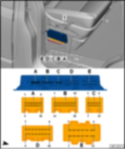
C -  Special purpose vehicle control unit -J608-
D -  Amplifier -R12-
q   Connector assignment

Fitting location:
under seat on front right
–  Back to overview
   
Connector assignment of TV tuner -R78-
VW TRANSPORTER 2013 Right seat box https://portal-diagnostov.com/license.html
https://portal-diagnostov.com/license.html Automotive Electricians Portal FZCO Automotive Electricians Portal FZCO
Obtenez l'accès à tous les schémas de câblage de la voitureDownload PDF file
A -  TV tuner -R78-
B -  2-pin connector -T2cl- , black

–  Back to overview
   
Connector assignment of amplifier -R12-
VW TRANSPORTER 2013 Right seat box https://portal-diagnostov.com/license.html
https://portal-diagnostov.com/license.html Automotive Electricians Portal FZCO Automotive Electricians Portal FZCO
Obtenez l'accès à tous les schémas de câblage de la voitureDownload PDF file
A -  Amplifier -R12-
B -  38-pin connector -T38- , black

  Note
For models without digital sound package only
–  Back to overview
   
Connector assignment of amplifier -R12-
VW TRANSPORTER 2013 Right seat box https://portal-diagnostov.com/license.html
https://portal-diagnostov.com/license.html Automotive Electricians Portal FZCO Automotive Electricians Portal FZCO
Obtenez l'accès à tous les schémas de câblage de la voitureDownload PDF file
A -  Amplifier -R12-
B -  23-pin connector -T23a- , green

  Note
For models with digital sound package only
–  Back to overview
   
Connector assignment of Voice amplification control unit -J656-
VW TRANSPORTER 2013 Right seat box https://portal-diagnostov.com/license.html
https://portal-diagnostov.com/license.html Automotive Electricians Portal FZCO Automotive Electricians Portal FZCO
Obtenez l'accès à tous les schémas de câblage de la voitureDownload PDF file
A -  Control unit for voice amplification -J656-
B -  23-pin connector -T23b- , black

–  Back to overview
   
Connector assignment of Reversing camera system control unit -J772-
VW TRANSPORTER 2013 Right seat box https://portal-diagnostov.com/license.html
https://portal-diagnostov.com/license.html Automotive Electricians Portal FZCO Automotive Electricians Portal FZCO
Obtenez l'accès à tous les schémas de câblage de la voitureDownload PDF file
A -  Reversing camera system control unit -J772-
B -  54-pin connector -T54b- , light blue

–  Back to overview
   
Connector assignment of trailer detector control unit -J345-
VW TRANSPORTER 2013 Right seat box https://portal-diagnostov.com/license.html
https://portal-diagnostov.com/license.html Automotive Electricians Portal FZCO Automotive Electricians Portal FZCO
Obtenez l'accès à tous les schémas de câblage de la voitureDownload PDF file
A -  Trailer detector control unit -J345-
B -  Not assigned
C -  12-pin connector -T12ac- , red

–  Back to overview
   
Connector assignment of Special purpose vehicles control unit -J608-
VW TRANSPORTER 2013 Right seat box https://portal-diagnostov.com/license.html
https://portal-diagnostov.com/license.html Automotive Electricians Portal FZCO Automotive Electricians Portal FZCO
Obtenez l'accès à tous les schémas de câblage de la voitureDownload PDF file
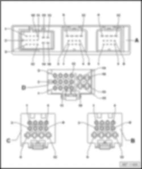
1 -  Special purpose vehicle control unit -J608-
A -  16-pin connector -T16u- , brown
C -  12-pin connector -T12am- , Not assigned
E -  12-pin connector -T12al- , black

–  Back to overview


VW TRANSPORTER 2013 All-wheel drive control unit J492

All-wheel drive control unit -J492-
Fitting location:
on the rear axle final drive, in front left area -position 1-
 
VW TRANSPORTER 2013 All-wheel drive control unit J492 https://portal-diagnostov.com/license.html
https://portal-diagnostov.com/license.html Automotive Electricians Portal FZCO Automotive Electricians Portal FZCO
Obtenez l'accès à tous les schémas de câblage de la voitureDownload PDF file
Connector assignment of all-wheel drive control unit -J492-
VW TRANSPORTER 2013 All-wheel drive control unit J492 https://portal-diagnostov.com/license.html
https://portal-diagnostov.com/license.html Automotive Electricians Portal FZCO Automotive Electricians Portal FZCO
Obtenez l'accès à tous les schémas de câblage de la voitureDownload PDF file
A -  All-wheel drive control unit -J492-
B -  8-pin connector -T8ad- , black

–  Back to overview


VW TRANSPORTER 2013 Operating and display unit for camping equipment E153

Operating and display unit for camping equipment -E153-
   
Fitting location:
on the roof console -position 1-
  Note
Only for models with camping equipment
 
VW TRANSPORTER 2013 Operating and display unit for camping equipment E153 https://portal-diagnostov.com/license.html
https://portal-diagnostov.com/license.html Automotive Electricians Portal FZCO Automotive Electricians Portal FZCO
Obtenez l'accès à tous les schémas de câblage de la voitureDownload PDF file
Connector assignment:
VW TRANSPORTER 2013 Operating and display unit for camping equipment E153 https://portal-diagnostov.com/license.html
https://portal-diagnostov.com/license.html Automotive Electricians Portal FZCO Automotive Electricians Portal FZCO
Obtenez l'accès à tous les schémas de câblage de la voitureDownload PDF file
A -  Operating and display unit for camping equipment -E153-
B -  6-pin connector -T6ap- , black
D -  2-pin connector -T2p- , black

–  Back to overview


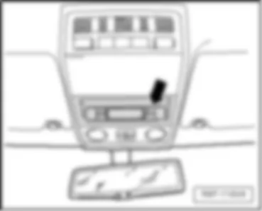
VW TRANSPORTER 2013 Display unit for roof J702

Display unit for roof -J702-
   
Fitting location:
on the roof console -arrow-
  Note
Only for models without camping equipment
–  Back to overview
 
VW TRANSPORTER 2013 Display unit for roof J702 https://portal-diagnostov.com/license.html
https://portal-diagnostov.com/license.html Automotive Electricians Portal FZCO Automotive Electricians Portal FZCO
Obtenez l'accès à tous les schémas de câblage de la voitureDownload PDF file
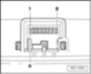
Connector assignment:
-Position 1 -16-pin connector -T16g/1-
-Position 8 -16-pin connector -T16g/8-
-Position 9 -16-pin connector -T16g/9-
–  Back to overview
 
VW TRANSPORTER 2013 Display unit for roof J702 https://portal-diagnostov.com/license.html
https://portal-diagnostov.com/license.html Automotive Electricians Portal FZCO Automotive Electricians Portal FZCO
Obtenez l'accès à tous les schémas de câblage de la voitureDownload PDF file


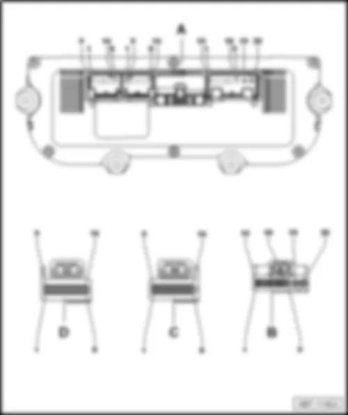
VW TRANSPORTER 2013

Climatronic control unit -J255- /A/C control module -J301-
Fitting location:
Dash panel centre -position B-
–  Back to overview
 
VW TRANSPORTER 2013 https://portal-diagnostov.com/license.html
https://portal-diagnostov.com/license.html Automotive Electricians Portal FZCO Automotive Electricians Portal FZCO
Obtenez l'accès à tous les schémas de câblage de la voitureDownload PDF file
Connector assignment of Climatronic control unit -J255-
VW TRANSPORTER 2013 https://portal-diagnostov.com/license.html
https://portal-diagnostov.com/license.html Automotive Electricians Portal FZCO Automotive Electricians Portal FZCO
Obtenez l'accès à tous les schémas de câblage de la voitureDownload PDF file
A -  Climatronic control unit -J255-
B -  20-pin connector -T20e- , black
D -  16-pin connector -T16p- , brown

–  Back to overview
   
Connector assignment of air conditioning system control unit -J301-
VW TRANSPORTER 2013 https://portal-diagnostov.com/license.html
https://portal-diagnostov.com/license.html Automotive Electricians Portal FZCO Automotive Electricians Portal FZCO
Obtenez l'accès à tous les schémas de câblage de la voitureDownload PDF file
A -  Air conditioning system control unit -J301-
B -  20-pin connector -T20c- , black
D -  5-pin connector -T5r- , black

–  Back to overview


VW TRANSPORTER 2013 Fresh air blower switch, rear E179

Fresh air blower switch, rear -E179-
   
Fitting location:
at front of dash panel-1-
  Note
Only for models without camping equipment
–  Back to overview
 
VW TRANSPORTER 2013 Fresh air blower switch, rear E179 https://portal-diagnostov.com/license.html
https://portal-diagnostov.com/license.html Automotive Electricians Portal FZCO Automotive Electricians Portal FZCO
Obtenez l'accès à tous les schémas de câblage de la voitureDownload PDF file
Fitting location:
in centre headliner -arrow-
  Note
Only for models without camping equipment
–  Back to overview
Fitting location:
 
VW TRANSPORTER 2013 Fresh air blower switch, rear E179 https://portal-diagnostov.com/license.html
https://portal-diagnostov.com/license.html Automotive Electricians Portal FZCO Automotive Electricians Portal FZCO
Obtenez l'accès à tous les schémas de câblage de la voitureDownload PDF file
on rear right of roof-1-
  Note
Only for models with camping equipment
–  Back to overview
 
VW TRANSPORTER 2013 Fresh air blower switch, rear E179 https://portal-diagnostov.com/license.html
https://portal-diagnostov.com/license.html Automotive Electricians Portal FZCO Automotive Electricians Portal FZCO
Obtenez l'accès à tous les schémas de câblage de la voitureDownload PDF file
Connector assignment Fresh air blower switch, rear -E179-
VW TRANSPORTER 2013 Fresh air blower switch, rear E179 https://portal-diagnostov.com/license.html
https://portal-diagnostov.com/license.html Automotive Electricians Portal FZCO Automotive Electricians Portal FZCO
Obtenez l'accès à tous les schémas de câblage de la voitureDownload PDF file
A -  Fresh air blower switch, rear -E179-
B -  16-pin connector -T16e- , black

–  Back to overview


VW TRANSPORTER 2013 Rear Climatronic operating and display unit E265

Rear Climatronic operating and display unit -E265-
   
Fitting location:
in centre headliner -arrow-
  Note
Only for models without camping equipment
–  Back to overview
 
VW TRANSPORTER 2013 Rear Climatronic operating and display unit E265 https://portal-diagnostov.com/license.html
https://portal-diagnostov.com/license.html Automotive Electricians Portal FZCO Automotive Electricians Portal FZCO
Obtenez l'accès à tous les schémas de câblage de la voitureDownload PDF file
Fitting location:
on rear right of roof -position A-
  Note
Only for models with camping equipment
–  Back to overview
 
VW TRANSPORTER 2013 Rear Climatronic operating and display unit E265 https://portal-diagnostov.com/license.html
https://portal-diagnostov.com/license.html Automotive Electricians Portal FZCO Automotive Electricians Portal FZCO
Obtenez l'accès à tous les schémas de câblage de la voitureDownload PDF file
Connector assignment Rear Climatronic operating and display unit -E265-
VW TRANSPORTER 2013 Rear Climatronic operating and display unit E265 https://portal-diagnostov.com/license.html
https://portal-diagnostov.com/license.html Automotive Electricians Portal FZCO Automotive Electricians Portal FZCO
Obtenez l'accès à tous les schémas de câblage de la voitureDownload PDF file
A -  Rear Climatronic operating and display unit -E265-
B -  20-pin connector -T20d- , black

–  Back to overview


VW TRANSPORTER 2013 Tachograph G24

Tachograph -G24-
Fitting location:
Central on the dash panel -arrow A-
 
VW TRANSPORTER 2013 Tachograph G24 https://portal-diagnostov.com/license.html
https://portal-diagnostov.com/license.html Automotive Electricians Portal FZCO Automotive Electricians Portal FZCO
Obtenez l'accès à tous les schémas de câblage de la voitureDownload PDF file
Connector assignment Tachograph -G24-
VW TRANSPORTER 2013 Tachograph G24 https://portal-diagnostov.com/license.html
https://portal-diagnostov.com/license.html Automotive Electricians Portal FZCO Automotive Electricians Portal FZCO
Obtenez l'accès à tous les schémas de câblage de la voitureDownload PDF file
A -  Tachograph -G24-
B -  8-pin connector -T8o- , white
D -  Not assigned
E -  8-pin connector -T8q- , brown

–  Back to overview


VW TRANSPORTER 2013

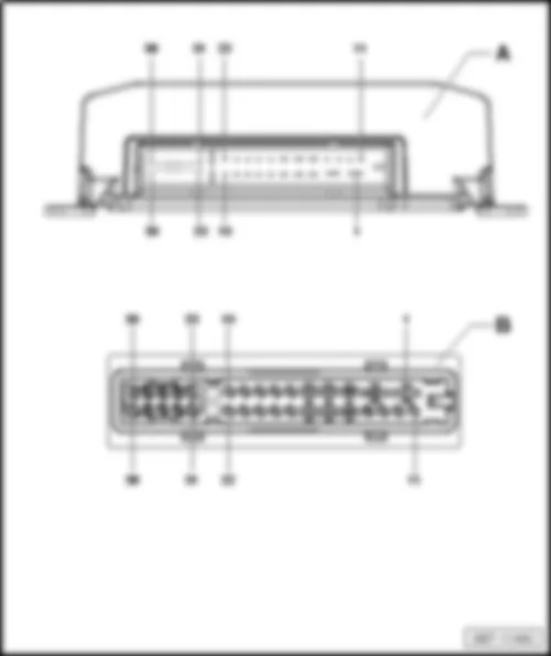
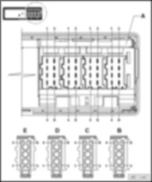
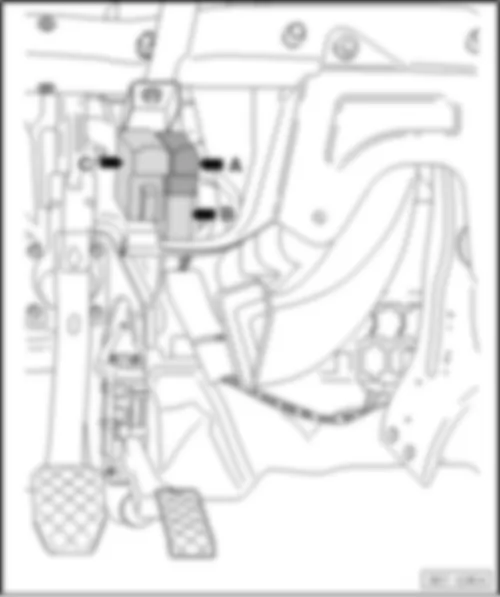
Headlight range control unit -J431- , Data bus diagnostic interface -J533- and Multimedia system control unit -J650-
Fitting location:
Headlight range control unit -J431- behind dash panel, near relay carrier cockpit -arrow A-26-pin connector -T26c- , black
Data bus diagnostic interface -J533- behind dash panel, near relay carrier cockpit -arrow B-20-pin connector -T20f- , red 1), 3)
Data bus diagnostic interface -J533- behind dash panel, near relay carrier cockpit -arrow B-20-pin connector -T20f- , red 2), 4), 5)
Multimedia system control unit -J650- behind dash panel, near relay carrier cockpit -arrow C-12-pin connector -T12z- , black
  Note
t  1) For models with start-stop-function only
t  2) For models with start-stop-function and without special purpose vehicles control unit only -J608-
t  3) Valid until May 2012
t  4) Valid from May 2012
t  5) Will be cancelled after October 2012
–  Back to overview
 
VW TRANSPORTER 2013 https://portal-diagnostov.com/license.html
https://portal-diagnostov.com/license.html Automotive Electricians Portal FZCO Automotive Electricians Portal FZCO
Obtenez l'accès à tous les schémas de câblage de la voitureDownload PDF file


VW TRANSPORTER 2013 Auxiliary air heater control unit J604

Auxiliary air heater control unit -J604-
Fitting location:
behind the underbody panelling on the right -arrow-
–  Back to overview
 
VW TRANSPORTER 2013 Auxiliary air heater control unit J604 https://portal-diagnostov.com/license.html
https://portal-diagnostov.com/license.html Automotive Electricians Portal FZCO Automotive Electricians Portal FZCO
Obtenez l'accès à tous les schémas de câblage de la voitureDownload PDF file


VW TRANSPORTER 2013 Lane change assist control unit J769

Lane change assist control unit -J769-
Fitting location:
on the left D-pillar -arrow-
–  Back to overview


VW TRANSPORTER 2013 Lane change assist control unit 2 J770

Lane change assist control unit 2 -J770-
 
VW TRANSPORTER 2013 Lane change assist control unit 2 J770 https://portal-diagnostov.com/license.html
https://portal-diagnostov.com/license.html Automotive Electricians Portal FZCO Automotive Electricians Portal FZCO
Obtenez l'accès à tous les schémas de câblage de la voitureDownload PDF file
Fitting location:
on the right D-pillar -arrow-
–  Back to overview
 
VW TRANSPORTER 2013 Lane change assist control unit 2 J770 https://portal-diagnostov.com/license.html
https://portal-diagnostov.com/license.html Automotive Electricians Portal FZCO Automotive Electricians Portal FZCO
Obtenez l'accès à tous les schémas de câblage de la voitureDownload PDF file


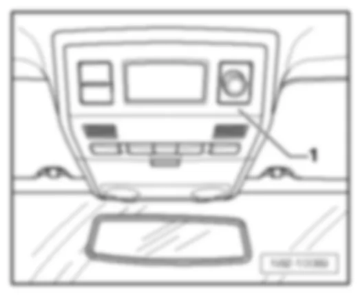
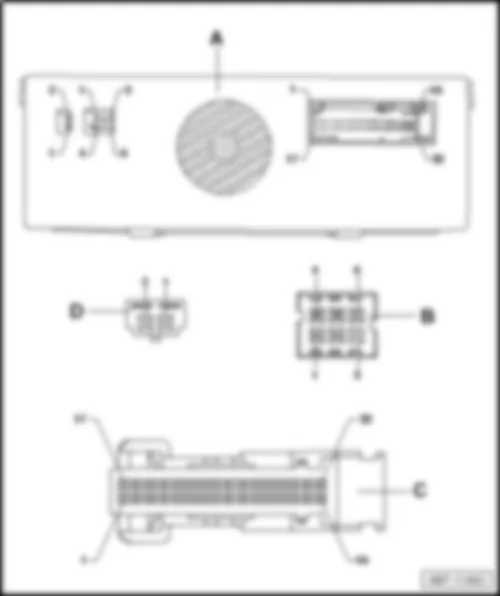
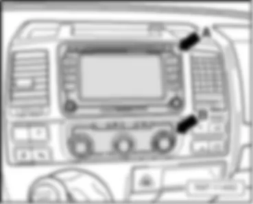
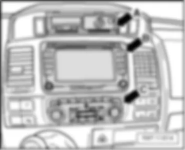
VW TRANSPORTER 2013

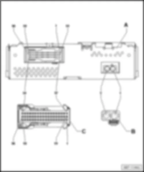
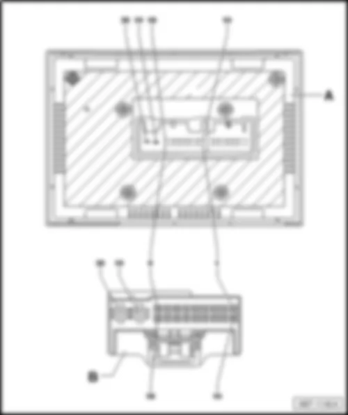
Radio -R- /control unit with display for radio and navigation -J503-
Fitting location:
Central in the dash panel -arrow A-
–  Back to overview
 
VW TRANSPORTER 2013 https://portal-diagnostov.com/license.html
https://portal-diagnostov.com/license.html Automotive Electricians Portal FZCO Automotive Electricians Portal FZCO
Obtenez l'accès à tous les schémas de câblage de la voitureDownload PDF file


VW TRANSPORTER 2013 Auxiliary coolant heater control unit J737

Auxiliary coolant heater control unit -J737-
Fitting location:
behind the underbody panelling on the left -arrow-
–  Back to overview


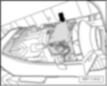
VW TRANSPORTER 2013

Left gas discharge bulb control unit -J343- and right gas discharge bulb control unit -J344-
 
VW TRANSPORTER 2013 https://portal-diagnostov.com/license.html
https://portal-diagnostov.com/license.html Automotive Electricians Portal FZCO Automotive Electricians Portal FZCO
Obtenez l'accès à tous les schémas de câblage de la voitureDownload PDF file
Fitting location:
on the right and left headlights -arrow-
–  Back to overview
 
VW TRANSPORTER 2013 https://portal-diagnostov.com/license.html
https://portal-diagnostov.com/license.html Automotive Electricians Portal FZCO Automotive Electricians Portal FZCO
Obtenez l'accès à tous les schémas de câblage de la voitureDownload PDF file


VW TRANSPORTER 2013

Control unit for left daytime running light and side light -J860- and control unit for right daytime running light and side light -J861-
Fitting location:
on the right and left headlights -arrow-
–  Back to overview
 
VW TRANSPORTER 2013 https://portal-diagnostov.com/license.html
https://portal-diagnostov.com/license.html Automotive Electricians Portal FZCO Automotive Electricians Portal FZCO
Obtenez l'accès à tous les schémas de câblage de la voitureDownload PDF file


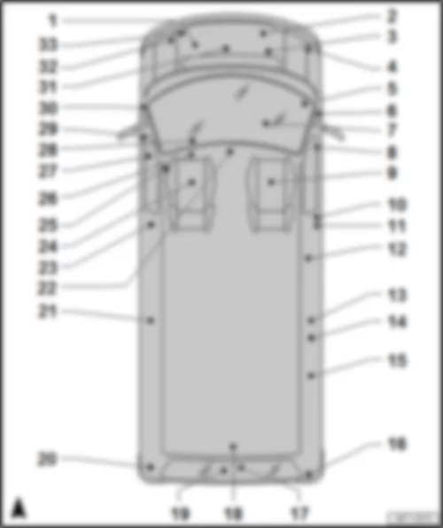
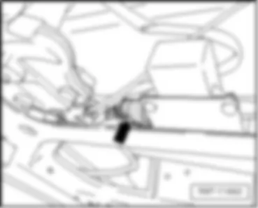
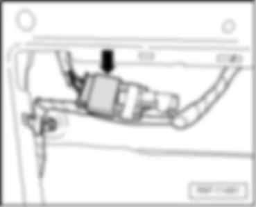
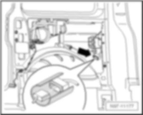
VW TRANSPORTER 2013 Overview of coupling stations

Overview of coupling stations
VW TRANSPORTER 2013 Overview of coupling stations https://portal-diagnostov.com/license.html
https://portal-diagnostov.com/license.html Automotive Electricians Portal FZCO Automotive Electricians Portal FZCO
Obtenez l'accès à tous les schémas de câblage de la voitureDownload PDF file
1 -  Coupling station on the fuel filter
q   Fitting location
2 -  Coupling station near generator
q   Fitting location
3 -  Coupling station on right in engine compartment
q   Fitting location
4 -  Coupling station near horn and dual tone horn
q   Fitting location
5 -  Coupling station on right A-pillar
q   Fitting location
6 -  Coupling station in right A-pillar
q   Fitting location
7 -  Coupling station behind the glove compartment
q   Fitting location
8 -  Coupling station in right door
q   Fitting locations
9 -  Coupling stations, right seat box
q   Fitting locations
10 -  Coupling station in right B-pillar
q   Fitting location
11 -  Coupling station on right B-pillar
q   Fitting location
12 -  Coupling station in right sliding door
q   Fitting location
13 -  Coupling station on right C-pillar
q   Fitting location
14 -  Coupling station in rear right side panel
q   Fitting location
15 -  Coupling station in right side panel
q   Fitting location
16 -  Right D-pillar coupling station
q   Fitting location
17 -  Coupling station in rear lid
q   Fitting location
18 -  Coupling station on rear of roof
q   Fitting location
19 -  Reversing camera coupling station
q   Fitting location
20 -  Coupling station on left D-pillar
q   Fitting location
21 -  Coupling station on left C-pillar
q   Fitting location
22 -  Coupling station for interior light
q   Fitting location
23 -  Coupling station in left B-pillar
q   Fitting location
24 -  Coupling station left seat box
q   Fitting locations
25 -  Coupling station for auxiliary heater
q   Fitting location
26 -  Coupling station on underbody
q   Fitting location
27 -  Coupling station for central locking SAFE function warning lamp
q   Fitting location
28 -  41-pin connector -T41- , grey, on steering column switch
q   Fitting location
29 -  Coupling station in left door
q   Fitting location
30 -  Coupling station left A-pillar
q   Fitting locations for coupling station in the left A-pillar
q   Fitting locations for coupling station on the left A-pillar, after August 2009
31 -  Coupling station on front of engine
q   Fitting location
32 -  Coupling station for E-box
q   Fitting location
33 -  Coupling station on radiator fan
q   Fitting location


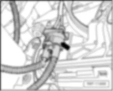
VW TRANSPORTER 2013 Coupling stations engine compartment

Coupling station on radiator fan
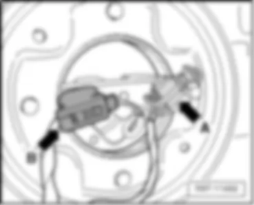
Pfeil -  4-pin connector -T4ak- , black , black, in the engine compartment, near radiator fan
  Note:
t  -T4ak- Boosted fan power
t  -T4ax- Low and medium fan power
–  Back to overview
 
VW TRANSPORTER 2013 Coupling stations engine compartment https://portal-diagnostov.com/license.html
https://portal-diagnostov.com/license.html Automotive Electricians Portal FZCO Automotive Electricians Portal FZCO
Obtenez l'accès à tous les schémas de câblage de la voitureDownload PDF file
  Note
The coolant reservoir has been removed in this illustration
–  Back to overview
 
VW TRANSPORTER 2013 Coupling stations engine compartment https://portal-diagnostov.com/license.html
https://portal-diagnostov.com/license.html Automotive Electricians Portal FZCO Automotive Electricians Portal FZCO
Obtenez l'accès à tous les schémas de câblage de la voitureDownload PDF file
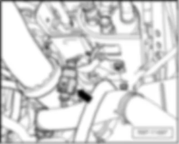
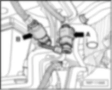
Pfeil B -  6-pin connector -T6a- , black, in engine compart., right
  Note
only for models with diesel engine
 
VW TRANSPORTER 2013 Coupling stations engine compartment https://portal-diagnostov.com/license.html
https://portal-diagnostov.com/license.html Automotive Electricians Portal FZCO Automotive Electricians Portal FZCO
Obtenez l'accès à tous les schémas de câblage de la voitureDownload PDF file
–  Back to overview
Pfeil -  6-pin connector -T6ax- , black, in engine compart., right
  Note
Only for models with petrol engine
 
VW TRANSPORTER 2013 Coupling stations engine compartment https://portal-diagnostov.com/license.html
https://portal-diagnostov.com/license.html Automotive Electricians Portal FZCO Automotive Electricians Portal FZCO
Obtenez l'accès à tous les schémas de câblage de la voitureDownload PDF file
Pfeil B -  14-pin connector -T14- , black, near horn and dual tone horn -H1-
–  Back to overview
 
VW TRANSPORTER 2013 Coupling stations engine compartment https://portal-diagnostov.com/license.html
https://portal-diagnostov.com/license.html Automotive Electricians Portal FZCO Automotive Electricians Portal FZCO
Obtenez l'accès à tous les schémas de câblage de la voitureDownload PDF file
2 -  3-pin connector -T3be- , green, in the engine, front
  Note
For models with engine code CJKA only
–  Back to overview
 
VW TRANSPORTER 2013 Coupling stations engine compartment https://portal-diagnostov.com/license.html
https://portal-diagnostov.com/license.html Automotive Electricians Portal FZCO Automotive Electricians Portal FZCO
Obtenez l'accès à tous les schémas de câblage de la voitureDownload PDF file
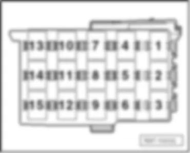
Coupling station, electronics box (15-pin)
t  In the e-box, in engine compart., left
 
VW TRANSPORTER 2013 Coupling stations engine compartment https://portal-diagnostov.com/license.html
https://portal-diagnostov.com/license.html Automotive Electricians Portal FZCO Automotive Electricians Portal FZCO
Obtenez l'accès à tous les schémas de câblage de la voitureDownload PDF file
Item   Connector/Designator Connector colour
1 - 10-pin connector -T10g- grey
2 - 10-pin connector -T10a- brown
3 - 10-pin connector -T10b- red
4 - 10-pin connector -T10m-1), 3) light pink
- 6-pin connector -T6q-2) brown
5 - 10-pin connector -T10e- white
6 - 10-pin connector -T10l- light green
7 - Not assigned -
8 - 17-pin connector -T17g- black
9 - 10-pin connector -T10c- yellow
10 - 10-pin connector -T10d- blue
11 - 10-pin connector -T10h- orange
12 - 10-pin connector -T10f- green
13 - 10-pin connector -T10- black
14 - 10-pin connector -T10k- purple
15 - 10-pin connector -T10j- dark brown

  Note
t  1) Only for models with diesel engine
t  2) Only for models with engine code AXA
t  3) Only for models with engine codes CJKA, CJKB
–  Back to overview
Coupling stations on right A-pillar
t  on right A-pillar
 
VW TRANSPORTER 2013 Coupling stations engine compartment https://portal-diagnostov.com/license.html
https://portal-diagnostov.com/license.html Automotive Electricians Portal FZCO Automotive Electricians Portal FZCO
Obtenez l'accès à tous les schémas de câblage de la voitureDownload PDF file
Item   Connector/Designator Connector colour
1 - 10-pin connector -T10ak- black
2 - Not assigned -
3 - 10-pin connector -T10al- red

–  Back to overview
   
Pfeil B -  Single connector -T1e- , yellow, in right A-pillar
Pfeil D -  Single connector -T1d- , blue, in right A-pillar
–  Back to overview
 
VW TRANSPORTER 2013 Coupling stations engine compartment https://portal-diagnostov.com/license.html
https://portal-diagnostov.com/license.html Automotive Electricians Portal FZCO Automotive Electricians Portal FZCO
Obtenez l'accès à tous les schémas de câblage de la voitureDownload PDF file
Coupling station behind the glove compartment
Pfeil A -  Single connector -T1ar- , black, behind the glove compartment (only for Climatic)
–  Back to overview
 
VW TRANSPORTER 2013 Coupling stations engine compartment https://portal-diagnostov.com/license.html
https://portal-diagnostov.com/license.html Automotive Electricians Portal FZCO Automotive Electricians Portal FZCO
Obtenez l'accès à tous les schémas de câblage de la voitureDownload PDF file


VW TRANSPORTER 2013 Coupling station in right door

Pfeil B -  Single connector -T1am- , yellow, in door on right
Pfeil D -  Single connector -T1ak- , brown, in door on right
–  Back to overview


VW TRANSPORTER 2013 Coupling stations, right seat box

Coupling stations, right seat box
 
VW TRANSPORTER 2013 Coupling stations, right seat box https://portal-diagnostov.com/license.html
https://portal-diagnostov.com/license.html Automotive Electricians Portal FZCO Automotive Electricians Portal FZCO
Obtenez l'accès à tous les schémas de câblage de la voitureDownload PDF file
Coupling station in right seat box
t  in right seat box
 
VW TRANSPORTER 2013 Coupling stations, right seat box https://portal-diagnostov.com/license.html
https://portal-diagnostov.com/license.html Automotive Electricians Portal FZCO Automotive Electricians Portal FZCO
Obtenez l'accès à tous les schémas de câblage de la voitureDownload PDF file
Item   Connector/Designator Connector colour
1 - Not assigned 3) -
- 10-pin connector -T10cd-1), 4) dark brown
2 - 6-pin connector -T6v- white
- 10-pin connector -T10bx-2), 4) blue
3 - 6-pin connector -T6x- purple
- 6-pin connector -T6cf-2), 4) white
4 - 10-pin connector -T10ba- blue
5 - 10-pin connector -T10bk- grey
6 - 6-pin connector -T6cb-1) black
7 - 6-pin connector -T6w- light pink
- 10-pin connector -T10bz-2), 4) light green
8 - 10-pin connector -T10ay- red
- 10-pin connector -T10by-2), 4) black
9 - 10-pin connector -T10be- green
- 6-pin connector -T6cj-2), 4) black
10 - 10-pin connector -T10av- brown
B - Not assigned -

  Note
t  1) Only for police special equipment (UF5)
t  2) Only for police special equipment (UF7)
t  3) Valid until May 2012
t  4) Valid after May 2012
–  Back to overview
   
Coupling station under front passenger seat
Pfeil -  3-pin connector -T3r- , yellow, under front passenger seat
–  Back to overview
 
VW TRANSPORTER 2013 Coupling stations, right seat box https://portal-diagnostov.com/license.html
https://portal-diagnostov.com/license.html Automotive Electricians Portal FZCO Automotive Electricians Portal FZCO
Obtenez l'accès à tous les schémas de câblage de la voitureDownload PDF file
Coupling station, 12-V socket
Pfeil -  2-pin connector -T2x- , black, under front passenger seat
–  Back to overview
 
VW TRANSPORTER 2013 Coupling stations, right seat box https://portal-diagnostov.com/license.html
https://portal-diagnostov.com/license.html Automotive Electricians Portal FZCO Automotive Electricians Portal FZCO
Obtenez l'accès à tous les schémas de câblage de la voitureDownload PDF file


VW TRANSPORTER 2013 Coupling station in right B-pillar

 -  3-pin connector -T3q- , yellow, B-pillar below, driver side 2
  Note
t  1) for models with left-hand drive only
t  2) for models with right-hand drive only
–  Back to overview
 
VW TRANSPORTER 2013 Coupling station in right B-pillar https://portal-diagnostov.com/license.html
https://portal-diagnostov.com/license.html Automotive Electricians Portal FZCO Automotive Electricians Portal FZCO
Obtenez l'accès à tous les schémas de câblage de la voitureDownload PDF file


VW TRANSPORTER 2013 Coupling station on right B-pillar

–  Back to overview
 
VW TRANSPORTER 2013 Coupling station on right B-pillar https://portal-diagnostov.com/license.html
https://portal-diagnostov.com/license.html Automotive Electricians Portal FZCO Automotive Electricians Portal FZCO
Obtenez l'accès à tous les schémas de câblage de la voitureDownload PDF file


VW TRANSPORTER 2013 Coupling station in right sliding door

Coupling station in right sliding door
Pfeil A -  2-pin connector -T2dj- , black, in the sliding door on the right
  Note
Another coupling point is located at the top of the sliding door on the right The connector, 3-pin -T3x- , black, is not illustrated.
t  2-pin connector -T2dm- , black, in the left sliding door
–  Back to overview
 
VW TRANSPORTER 2013 Coupling station in right sliding door https://portal-diagnostov.com/license.html
https://portal-diagnostov.com/license.html Automotive Electricians Portal FZCO Automotive Electricians Portal FZCO
Obtenez l'accès à tous les schémas de câblage de la voitureDownload PDF file


VW TRANSPORTER 2013 Coupling station on right C-pillar

  Note
behind the right side trim
–  Back to overview
 
VW TRANSPORTER 2013 Coupling station on right C-pillar https://portal-diagnostov.com/license.html
https://portal-diagnostov.com/license.html Automotive Electricians Portal FZCO Automotive Electricians Portal FZCO
Obtenez l'accès à tous les schémas de câblage de la voitureDownload PDF file


VW TRANSPORTER 2013 Coupling station in rear right side panel

Coupling station in rear right side panel
Pfeil -  8-pin connector -T8g- , black, in rear right side panel
–  Back to overview
 
VW TRANSPORTER 2013 Coupling station in rear right side panel https://portal-diagnostov.com/license.html
https://portal-diagnostov.com/license.html Automotive Electricians Portal FZCO Automotive Electricians Portal FZCO
Obtenez l'accès à tous les schémas de câblage de la voitureDownload PDF file


VW TRANSPORTER 2013 Coupling station in right side panel

Coupling station in right side panel
Pfeil -  4-pin connector -T4am- , black, in rear right side panel
–  Back to overview
 
VW TRANSPORTER 2013 Coupling station in right side panel https://portal-diagnostov.com/license.html
https://portal-diagnostov.com/license.html Automotive Electricians Portal FZCO Automotive Electricians Portal FZCO
Obtenez l'accès à tous les schémas de câblage de la voitureDownload PDF file


VW TRANSPORTER 2013 Right D-pillar coupling station

t  on the right D-pillar
–  back to overview
 
VW TRANSPORTER 2013 Right D-pillar coupling station https://portal-diagnostov.com/license.html
https://portal-diagnostov.com/license.html Automotive Electricians Portal FZCO Automotive Electricians Portal FZCO
Obtenez l'accès à tous les schémas de câblage de la voitureDownload PDF file


VW TRANSPORTER 2013 Coupling station in rear lid

–  Back to overview
 
VW TRANSPORTER 2013 Coupling station in rear lid https://portal-diagnostov.com/license.html
https://portal-diagnostov.com/license.html Automotive Electricians Portal FZCO Automotive Electricians Portal FZCO
Obtenez l'accès à tous les schémas de câblage de la voitureDownload PDF file


VW TRANSPORTER 2013 Coupling station on rear of roof

–  Back to overview
 
VW TRANSPORTER 2013 Coupling station on rear of roof https://portal-diagnostov.com/license.html
https://portal-diagnostov.com/license.html Automotive Electricians Portal FZCO Automotive Electricians Portal FZCO
Obtenez l'accès à tous les schémas de câblage de la voitureDownload PDF file


VW TRANSPORTER 2013 Reversing camera coupling station

Reversing camera coupling station
Pfeil A -  Single connector -T1at- , grey, in the rear lid
–  Back to overview
 
VW TRANSPORTER 2013 Reversing camera coupling station https://portal-diagnostov.com/license.html
https://portal-diagnostov.com/license.html Automotive Electricians Portal FZCO Automotive Electricians Portal FZCO
Obtenez l'accès à tous les schémas de câblage de la voitureDownload PDF file


VW TRANSPORTER 2013 Coupling station on left D-pillar

Pfeil B -  12-pin connector -T12v- , black, coupling station left D-pillar
–  Back to overview
 
VW TRANSPORTER 2013 Coupling station on left D-pillar https://portal-diagnostov.com/license.html
https://portal-diagnostov.com/license.html Automotive Electricians Portal FZCO Automotive Electricians Portal FZCO
Obtenez l'accès à tous les schémas de câblage de la voitureDownload PDF file


VW TRANSPORTER 2013 Coupling station on left C-pillar

  Note
behind the left side trim
–  Back to overview
 
VW TRANSPORTER 2013 Coupling station on left C-pillar https://portal-diagnostov.com/license.html
https://portal-diagnostov.com/license.html Automotive Electricians Portal FZCO Automotive Electricians Portal FZCO
Obtenez l'accès à tous les schémas de câblage de la voitureDownload PDF file


VW TRANSPORTER 2013 Coupling station in left B-pillar

 -  3-pin connector -T3m- , yellow, B-pillar below, front passenger side 2
  Note
t  1) for models with left-hand drive only
t  2) for models with right-hand drive only
–  Back to overview


VW TRANSPORTER 2013 Coupling station left seat box

Coupling station left seat box
 
VW TRANSPORTER 2013 Coupling station left seat box https://portal-diagnostov.com/license.html
https://portal-diagnostov.com/license.html Automotive Electricians Portal FZCO Automotive Electricians Portal FZCO
Obtenez l'accès à tous les schémas de câblage de la voitureDownload PDF file
Coupling station in left seat box
t  under the left seat box
 
VW TRANSPORTER 2013 Coupling station left seat box https://portal-diagnostov.com/license.html
https://portal-diagnostov.com/license.html Automotive Electricians Portal FZCO Automotive Electricians Portal FZCO
Obtenez l'accès à tous les schémas de câblage de la voitureDownload PDF file
Item   Connector/Designator Connector colour
1 - 10-pin connector -T10aa- dark brown
2 - 17-pin connector -T17f- brown
3 - 6-pin connector -T6j- red
4 - 6-pin connector -T6bn-1)
6-pin connector -T6df-2), 3)
grey
5 - 10-pin connector -T10t- black
6 - 10-pin connector -T10u-
10-pin connector -T10bu-2), 3)
blue
7 - 10-pin connector -T10o- light green
8 - 10-pin connector -T10bj-1) yellow
9 - - 6-pin connector -T6h- purple
10-pin connector -T10ce-2), 3) orange
10 - 10-pin connector -T10q- green
A - Not assigned -
B - 17-pin connector -T17j- white
C - 10-pin connector -T10bh-1)
6-pin connector -T6dg-2), 3)
purple
D - see "Fitting locations: Fuses" -

  Note
t  1) Only for models with electric interface for external use (UF1)
t  2) Only for models with provision for electric interface for external use (UF5)
t  3) Valid from May 2012
–  Back to overview
   
Coupling station under driver seat
Pfeil A -  2-pin connector -T2dd- , black, under the driver's seat
  Note
Another coupling point is located under the driver's seat. The 8-pin connector -T8s- , black, is not illustrated.
–  Back to overview
 
VW TRANSPORTER 2013 Coupling station left seat box https://portal-diagnostov.com/license.html
https://portal-diagnostov.com/license.html Automotive Electricians Portal FZCO Automotive Electricians Portal FZCO
Obtenez l'accès à tous les schémas de câblage de la voitureDownload PDF file
Coupling points for special vehicle
t  under the left seat box
 
VW TRANSPORTER 2013 Coupling station left seat box https://portal-diagnostov.com/license.html
https://portal-diagnostov.com/license.html Automotive Electricians Portal FZCO Automotive Electricians Portal FZCO
Obtenez l'accès à tous les schémas de câblage de la voitureDownload PDF file
Item   Connector/Designator Connector colour
1 - 10-pin connector -T10bp- green
2 - 10-pin connector -T10bq- orange
3 - 10-pin connector -T10br- blue

–  Back to overview


VW TRANSPORTER 2013 Coupling station for auxiliary heater

Coupling station for auxiliary heater
Pfeil A -  8-pin connector -T8d- , black, on the underbody, beside the auxiliary heater
–  Back to overview
 
VW TRANSPORTER 2013 Coupling station for auxiliary heater https://portal-diagnostov.com/license.html
https://portal-diagnostov.com/license.html Automotive Electricians Portal FZCO Automotive Electricians Portal FZCO
Obtenez l'accès à tous les schémas de câblage de la voitureDownload PDF file


VW TRANSPORTER 2013 Coupling station on underbody

Pfeil B -  2-pin connector -T2cr- , brown, on the underbody, near cross panel
Pfeil D -  3-pin connector -T3bc- , black, on the underbody, near cross panel
  Note
only for models with diesel engine
 
VW TRANSPORTER 2013 Coupling station on underbody https://portal-diagnostov.com/license.html
https://portal-diagnostov.com/license.html Automotive Electricians Portal FZCO Automotive Electricians Portal FZCO
Obtenez l'accès à tous les schémas de câblage de la voitureDownload PDF file
–  Back to overview
Pfeil -  4-pin connector -T4k- , black, on the underbody, beside the auxiliary heater
  Note
Only for models with petrol engine
–  Back to overview
 
VW TRANSPORTER 2013 Coupling station on underbody https://portal-diagnostov.com/license.html
https://portal-diagnostov.com/license.html Automotive Electricians Portal FZCO Automotive Electricians Portal FZCO
Obtenez l'accès à tous les schémas de câblage de la voitureDownload PDF file


VW TRANSPORTER 2013 Coupling station for central locking SAFE function warning lamp

–  Back to overview
 
VW TRANSPORTER 2013 Coupling station for central locking SAFE function warning lamp https://portal-diagnostov.com/license.html
https://portal-diagnostov.com/license.html Automotive Electricians Portal FZCO Automotive Electricians Portal FZCO
Obtenez l'accès à tous les schémas de câblage de la voitureDownload PDF file


VW TRANSPORTER 2013 Coupling station for interior light

Coupling station for interior light
Pfeil A -  2-pin connector -T2r- , black, behind the interior light1)
  Note
t  1) Only for models with telephone
t  2) Only for models with roof console
–  Back to overview
 
VW TRANSPORTER 2013 Coupling station for interior light https://portal-diagnostov.com/license.html
https://portal-diagnostov.com/license.html Automotive Electricians Portal FZCO Automotive Electricians Portal FZCO
Obtenez l'accès à tous les schémas de câblage de la voitureDownload PDF file


VW TRANSPORTER 2013 Coupling station in left door

Coupling station in left door
Pfeil A -  Single connector -T1af- , green, in left door
Pfeil C -  Single connector -T1ae- , white, in left door
–  Back to overview


VW TRANSPORTER 2013 Coupling stations left A-pillar

Coupling stations left A-pillar
 
VW TRANSPORTER 2013 Coupling stations left A-pillar https://portal-diagnostov.com/license.html
https://portal-diagnostov.com/license.html Automotive Electricians Portal FZCO Automotive Electricians Portal FZCO
Obtenez l'accès à tous les schémas de câblage de la voitureDownload PDF file
Pfeil B -  Single connector -T1ac- , green, in the left A-pillar
–  Back to overview
 
VW TRANSPORTER 2013 Coupling stations left A-pillar https://portal-diagnostov.com/license.html
https://portal-diagnostov.com/license.html Automotive Electricians Portal FZCO Automotive Electricians Portal FZCO
Obtenez l'accès à tous les schémas de câblage de la voitureDownload PDF file
Coupling station on left A-pillar, from August 2009
t  on left A-pillar
 
VW TRANSPORTER 2013 Coupling stations left A-pillar https://portal-diagnostov.com/license.html
https://portal-diagnostov.com/license.html Automotive Electricians Portal FZCO Automotive Electricians Portal FZCO
Obtenez l'accès à tous les schémas de câblage de la voitureDownload PDF file
Item   Connector/Designator Connector colour
1 - 10-pin connector -T10ad- red
2 - Not assigned -
3 - Not assigned -
4 - 10-pin connector -T10ab- white
5 - 17-pin connector -T17k- green
6 - 17-pin connector -T17l- black
7 - 10-pin connector -T10ag- brown
8 - 17-pin connector -T17m- red
9 - 10-pin connector -T10af- blue
10 - Not assigned -
A-D - Not assigned -

–  Back to overview
   
Coupling station on left A-pillar, from May 2011
t  on left A-pillar
 
VW TRANSPORTER 2013 Coupling stations left A-pillar https://portal-diagnostov.com/license.html
https://portal-diagnostov.com/license.html Automotive Electricians Portal FZCO Automotive Electricians Portal FZCO
Obtenez l'accès à tous les schémas de câblage de la voitureDownload PDF file
Item   Connector/Designator Connector colour
1 - 17-pin connector -T17l- black
2 - 10-pin connector -T10ab- white
3 - 17-pin connector -T17k- green
4 - Not assigned -
5 - Not assigned -
6 - 10-pin connector -T10ad- red
7 - 10-pin connector -T10ag- brown
8 - 17-pin connector -T17m- red
9 - 10-pin connector -T10af- blue
10 - Not assigned -
A-D - Not assigned -

–  Back to overview
   
Contact assignment Harness connector, 41-pin -T41- , grey, on steering column switch
1 -  T41/1 not assigned
2 -  T41/2 steering angle sensor -G85- (CAN Low)
3 -  T41/3 steering angle sensor -G85- (CAN High)
4 -  T41/4 steering angle sensor -G85- (31)
5 -  T41/5 steering angle sensor -G85- (30)
6 -  T41/6 steering angle sensor -G85- (15)
7 -  T41/7 igniter for driver side airbag -N95- (+)
8 -  T41/8 igniter for driver side airbag -N95- (-)
9 -  T41/9 control module for multifunction steering wheel -J453- (15/30)
10 -  T41/10 control module for multifunction steering wheel -J453- (LIN)
11 -  T41/11 signal horn actuation -H- (71a)
12 -  T41/12 signal horn actuation -H- (31)
13 -  T41/13 not assigned
14 -  T41/14 not assigned
15 -  T41/15 intermittent wiper switch -E22- (53b, 2nd stage)
16 -  T41/16 intermittent wiper switch -E22- (53, 1st stage)
17 -  T41/17 sliding sunroof adjustment regulator -E38-
18 -  T41/18 memory switch for multifunction display -E109- (MFA - Reset)
19 -  T41/19 washer pump switch (automatic wash/wipe and headlight washer system) -E44- (31)
20 -  T41/20 washer pump switch (automatic wash/wipe and headlight washer system) -E44- (53c)
21 -  T41/21 washer pump -V5- and rear window wiper motor -V12-
22 -  T41/22 intermittent wiper switch -E22- and / washer pump switch (automatic wash/wipe and headlight washer system) -E44- (15)
23 -  T41/23 call-up button for multifunction display -E86- (MFA -)
24 -  T41/24 call-up button for multifunction display -E86- (MFA +)
25 -  T41/25 not assigned
26 -  T41/26 cruise control switch -E45- (I/O)
27 -  T41/27 cruise control switch -E45- (CANCEL)
28 -  T41/28 cruise control switch -E45- and cruise control SET button -E227- (15)
29 -  T41/29 cruise control switch -E45- (I/O)
30 -  T41/30 cruise control SET button -E227- (SET)
31 -  T41/31 cruise control SET button -E227- (Resume)
32 -  T41/32 turn signal switch -E2- (R)
33 -  T41/33 turn signal switch -E2- (31)
34 -  T41/34 turn signal switch -E2- (L)
35 -  T41/35 not assigned
36 -  T41/36 not assigned
37 -  T41/37 not assigned
38 -  T41/38 Headlight dipper and flasher switch -E4- (30)
39 -  T41/39 Headlight dipper and flasher switch -E4- (56a)
40 -  T41/40 Headlight dipper and flasher switch -E4- (56b)
41 -  T41/41 Headlight dipper and flasher switch -E4- (56)
–  Back to overview
 
VW TRANSPORTER 2013 Coupling stations left A-pillar https://portal-diagnostov.com/license.html
https://portal-diagnostov.com/license.html Automotive Electricians Portal FZCO Automotive Electricians Portal FZCO
Obtenez l'accès à tous les schémas de câblage de la voitureDownload PDF file