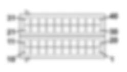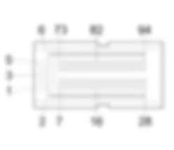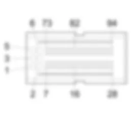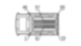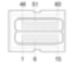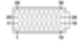

Components - CODE - Fiat DOBLO 1.9 JTD 8V Da 10/2000
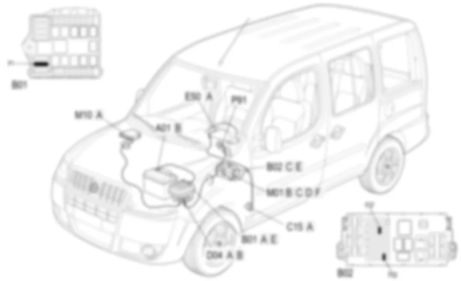
| Component code | Description | Reference to the assembly |
| B001 | JUNCTION UNIT | |
| B2 | JUNCTION UNIT UNDER DASHBOARD | |
| C15 | DASHBOARD EARTH, DRIVER''S SIDE | |
| D004 | FRONT/ENGINE COUPLING | |
| E50 | INSTRUMENT PANEL | |
| H001 | IGNITION SWITCH | |
| M001 | BODY COMPUTER | |
| M010 | ENGINE MANAGEMENT ECU | |
| P91 | AERIAL FOR FIAT-CODE |
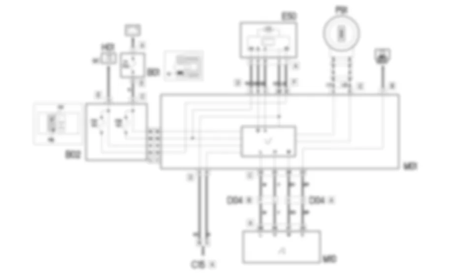
To increase protection against theft attempts, an engine immobilizer system known as the FIAT CODE-2 is used.The keys are equipped with an electronic Transponder device that sends a coded signal to a special electronic CODE control unit. if it recognizes the code sent, it allows the engine to be started.The code used in the dialogue, that takes place via an aerial coaxial to the ignition switch, varies each time the engine is started (rolling code): therefore the code cannot be reproduced even using electronic scanners.The role of the body computer is to recognise the key inserted in the ignition switch: it contains the secret code used in the dialogue with the key transponder.All the codes for the enabled keys and the code used in the dialogue with the engine management control unit are contained in the computer: when the key is turned to the ON position for the first time, if the key is correctly recognized, this code is transferred to the engine management control unit which remains indelibly linked to the Body Computer.On this version, a serial line W connects the body computer and engine control unit to carry signals required for key recognition and the exchange of codes in recovery mode.In the Code system, the control unit supply lines are protected a maxifuse that also protects the engine management system, body computer supply fuses and the control panel contained in the under-dashboard junction unit.
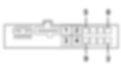
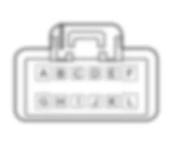
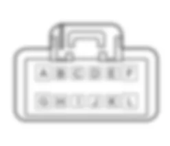
The body computer M01 receives a supply controlled by the ignition and a direct supply at pins 11 of connector E (INT) and pin A of connector C of under-dashboard junction unit B02 .The direct power supply is protected by fuse F1 in engine compartment junction unit B01.These lines also supply the control panel by splitting inside under-dashboard junction unit B02 (MAXIFUSE). These lines are protected by fuses F37 and F53.Pins 8 and 9 of connector E of the body computer M01 are earthed. This reference signal is also supplied to the panel via pin 36 connector F of the body computer.Pins 4 and 5 of connector C of body computer M01 are connected by means of two cables to aerial P91 located coaxially on the ignition switch in order to receive an insertion signal from the key fitted with a trasponder.Body computer M01 communicates with engine management unit M10 via pins 32 and 33 connector C (C-CAN line) and pins 83 and 84 of connector A of engine management unit M10.The key is recognised and the codes are exchanged via this line.Engine control unit M10 sends a diagnostic signal (K line) from pin 25 of connector A to pin 20 connector C of the body computer.Communication between the body computer and the engine control unit takes place via the C-CAN network and via a two-way recovery serial line (line connecting pin 29 connector C of body computer M01 and pin 47 connector A of engine control unit M10), used if the CAN network is faulty.The diagnostic line is connected to pin 7 connector B of body computer M01.The self-diagnostic system also generates a signal that can be used to display the vehicle protection system fault warning light located in instrument panel E50 and sent via the B-CAN line to pins 8 and 9 connector A.

 Deutsch
 English
 English
 Español
 Nederlands
 Русский

