
G - TESTS W/CODES 1990 ENGINE PERFORMANCE Audi Self-Diagnostics
Audi 565 1990 - INTRODUCTION
If no faults were found after performing tests in BASIC TESTING article, go to ENTERING SELF-DIAGNOSTICS in this article. If no fault codes or only pass codes are present, go to TESTS W/O CODES article for diagnosis by symptom (i.e. ROUGH IDLE, NO START, etc.).
Audi 565 1990 - SELF-DIAGNOSTIC SYSTEM HARD FAILURES
Hard failures cause malfunction light to illuminate and remain on until problem is repaired. If light comes on and remains on (light may flash) during vehicle operation, cause of malfunction must be determined using diagnostic (code) charts. If a sensor fails, control unit will use a substitute value in its calculations to continue engine operation. In this condition, commonly known as limp mode, the vehicle runs but driveability will not be optimum.
Audi 565 1990 - INTERMITTENT FAILURES
Intermittent failures may cause malfunction light to flicker on-and-off. Light goes out after intermittent fault goes away. The corresponding trouble code may be retained in control unit memory, depending on the system.
If related fault does not reoccur within a certain time frame, related trouble code will be erased from control unit memory. Intermittent failures may be caused by sensor, connector or wiring related problems. See INTERMITTENTS in TESTS W/O CODES article.
Audi 565 1990 - ENTERING SELF-DIAGNOSTICS CIS-E III
Drive vehicle for a minimum of 5 minutes to allow fault information to be stored. Engine speed must reach 3000 RPM, and turbo boost must be achieved during test drive. If a no-start condition exists, operate starter for at least 6 seconds then return ignition to ON position. On vehicles with one knock sensor, DO NOT turn ignition off or fault memory will be erased. (On vehicles with two knock sensors codes are stored in permanent memory, and must be intentionally erased).
Audi 565 1990 - CIS Motronic Engine Code 3B
Drive vehicle for a minimum of 5 minutes to allow fault information to be stored. On California models, when ECU detects a temporary fault, the CHECK light on the instrument panel will flash. Light will continue to flash until ignition is turned off. ECU may clear fault on the next engine start, and CHECK light will stop flashing unless fault is detected again. Vehicle will have to be test driven for at least 5 minutes to reset fault. When ECU detects a permanent fault, CHECK light will flash and fault will remain in ECU memory until physically erased.
On Federal models, retrieving codes requires use of a VAG 1551 tester.
On Federal and California models, codes must be retrieved before they can be erased, and codes must be erased with VAG 1551 . Follow tool manufacturers instructions and screen prompts.
Audi 565 1990 - RETRIEVING CODES CIS-E III (Engine Code MC With 1 Knock Sensor)
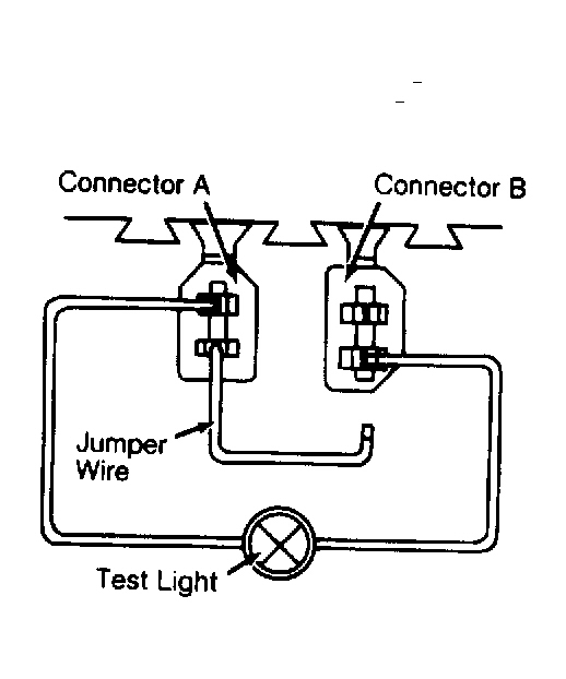
- Locate 2 diagnostic connectors in drivers footwell area. Connect a test light between connectors A and B. See Fig. 1 .
- Connect a jumper wire to other terminal in connector A. Touch other end of jumper wire to remaining terminal in connector B for at least 4 seconds. Fault codes will now be displayed by the flashing CHECK light (California vehicles) or test light (Federal vehicles).
NOTE: Pay careful attention to flashing light since there are no discernible break points between 4-digit fault codes. - Trouble codes will be flashed as 4-digit numbers. There is a 1/2-second pause between flashes. Add flashes together to obtain code for each of the four digits. See Fig. 3 . There is a 2 1/2-second pause before code for next digit is flashed. After code for the fourth (last) digit is flashed, there's another 2 1/2-second pause before fault code is repeated.
- Fault code will be repeated until the ignition is turned off. Record fault code. Check the list of input codes and possible problems. See CIS-E III SINGLE KNOCK SENSOR ENGINE CODE MC CONTROL INPUT FAULT CODES table.
- Check and repair circuits and/or sensors as indicated. See appropriate test in SYSTEM & COMPONENT TESTING article. After the fault is corrected, check for additional codes.
- To display next fault code, repeat step 2). (Touch remaining end of jumper wire to remaining terminal in connector B for at least 4 seconds.) See Fig. 1 . Continue checking for fault codes until Code 0000 is displayed, indicating end of diagnosis. Code 0000 is indicated by light remaining off for approximately 15 seconds after start signal.
Audi 565 1990 CIS-E III SINGLE KNOCK SENSOR ENGINE CODE MC CONTROL INPUT FAULT CODES
Code System Affected Probable Cause 1111 Control Unit Defective Memory Circuits 2111 Engine Speed Sensor Control Unit Not Receiving Signal 2112 Reference Sensor (1) Control Unit Not Receiving Signal 2113 Hall Sender In Distributor (2) Control Unit Not Receiving Signal 2221 Control Unit Pressure Sensor Vacuum Hose Leaks/Plugged 2221 Control Unit Pressure Sensor Defective Pressure Sensor 2141 Knock Regulation (3) Engine or Ignition Knock 2142 Knock Sensor Defective Sensor or Sensor Wiring 2123 Full Throttle Switch Faulty Switch or Wiring Problem 2121 Idle Switch Faulty Switch or Wiring Problem 2312 Coolant Temp. Sensor Sensor or Wiring Defective 2322 Intake Air Temp. Sensor Sensor or Wiring Defective 2342 Oxygen Sensor Sensor or Sensor Wiring Defective 4444 No Faults Have Been Recorded N/A 0000 End of Diagnosis (4)
(1) Another cause could be a misadjusted distributor.
(2) Another cause could be signal is out of phase (misadjusted distributor).
(3) This would cause ignition timing to be retarded the maximum amount (7.8 degrees).
(4) This code is indicated by the light staying off for approximately 15 seconds after the start signal.
Audi 565 1990 - CIS-E III (Engine Code MC With 2 Knock Sensors)
NOTE: Before proceeding, verify fuse No. 21 is OK.
For OBD vehicles, only connectors A and B are to be connected to diagnostic connectors 1 and 2.
- Connect LED tester (US 1115 ) using adaptors (VW 1594 ) between rear terminals of diagnostic connector Nos. 1 and 3.
- Connect adaptors (VW 1594 ) to lower terminals of diagnostic connector Nos. 1 and 2. See Fig. 2 .
- Start engine and allow to idle. (If engine will not run, crank engine with starter for at least 5 seconds. Do not turn ignition off.
- Connect adaptor A (ground) and adaptor B for at least 4 seconds. See Fig. 2 . LED tester will illuminate. If tester does not illuminate, check tester connections and wiring between engine control unit and diagnostic connectors. See WIRING DIAGRAMS article.
- Disconnect adaptor A and B. LED should begin flashing. Fault codes are now be displayed by the flashing test light.
NOTE: Pay careful attention to flashing light since there are no discernible break points between 4-digit fault codes. - Trouble codes will be flashed as 4-digit numbers. There is a 1/2-second pause between flashes. Add flashes together to obtain code for each of the four digits. There is a 2 1/2-second pause before code for next digit is flashed. After code for the fourth (last) digit is flashed, there's another 2 1/2-second pause before fault code is repeated.
- Fault code will be repeated until the ignition is turned off. Record fault code. Check the list of input codes and possible problems. See CIS-E III DOUBLE KNOCK SENSOR ENGINE CODE MC CONTROL INPUT FAULT CODES table.
- Check and repair circuits and/or sensors as indicated. See appropriate test in SYSTEM & COMPONENT TESTING article. After the fault is corrected, check for additional codes.
- To display next fault code, repeat step 2). (Touch remaining end of jumper wire to remaining terminal in connector B for at least 4 seconds.) See Fig. 2 . Continue checking for fault codes until Code 0000 is displayed, indicating end of diagnosis. Code 0000 is indicated by light remaining off for approximately 15 seconds after start signal.
Audi 565 1990 - Output Codes - CIS-E III (Engine Code MC With 2 Knock Sensors)
- Control unit circuitry allows checking of certain components by generating specific output signals. During output diagnosis, components can be checked by listening for their operation. Diagnostic output code will flash during testing, indicating which step the control unit is in.
- Turn ignition switch off to erase fault memory. Turn ignition on. DO NOT crank or start engine. If engine is started, system will automatically switch to input testing when diagnostic procedure are activated.
- To activate diagnostic procedure, locate 2 diagnostic connectors in drivers footwell area. Connect a test light between connectors A and B. See Fig. 2 .
- Connect a jumper wire to other terminal in connector A. Touch other end of jumper wire to remaining terminal in connector B for at least 4 seconds.
- This will activate the first of 5 output steps. To go to the next output step, touch end of jumper wire to remaining terminal in connector B again for at least 4 seconds. See Fig. 2 .
- First step (Code 4433) will activate fuel pump. Pump will continue to activate through all 5 steps until diagnostic procedure is ended by turning off ignition.
- Second step (Code 4441) will operate OXS frequency valve at 50 percent duty cycle until next step is activated.
- Third step (Code 4442) will cause wastegate frequency valve to switch on-and-off until next step is activated.
- Fourth step (Code 4443) will cause cold start valve to switch on-and-off for about 10 seconds.
- Fifth step (Code 4343) causes carbon canister shutoff valve to switch on-and-off until step is terminated by turning ignition switch off. If necessary, output tests may be continued by repeating steps 3) through 10).
- If any device does not operate as indicated during output tests, see appropriate test in SYSTEMS & COMPONENT TESTING article.
Audi 565 1990 CIS-E III DOUBLE KNOCK SENSOR ENGINE CODE MC CONTROL INPUT FAULT CODES
Code System Affected Probable Cause 1111 ICU or FICU Defective Memory Circuits 2111 Engine Speed Sensor Physical Sensor Or Flwheel Damage, Debris, Incorrect Gap, Defective Control Unit 2112 Ignition Timing Point Sender Physical Sensor Or Flwheel Damage, Debris, Incorrect Gap, Defective ICU 2113 Hall Sender Sensor, Sensor Adjustment, Defective ICU Or Wiring 2121 Idle Switch Switch Stuck Closed or Wiring Problem 2123 WOT Switch Switch Stuck Closed or Wiring Problem 2141 First Knock Regulator Engine or Ignition Knock Or Knock Control Module In ICU 2142 Knock Sensor I Defective Sensor, Wiring Or ICU 2143 Second Knock Regulator Engine or Ignition Knock Or Knock Control Module In ICU 2144 Knock Sensor II Defective Sensor, Wiring Or ICU 2214 Upper RPM Limit Exceeded Engine Speed Too High 2221 Intake Manifold Broken Or Missing Vacuum Between Manifold Andd ICU 2222 Intake Manifold Pressure Sender Defective Sender In ICU 2224 Engine Manifold Pressure Dump Valve Or Vacuum Lines 2312 Coolant Temp. Sensor No Signal From Sensor 2342 O2 Sensor No Signal From Sensor 4444 No Faults Stored N/A 0000 End of Diagnosis N/A
Audi 565 1990 - CIS Motronic Engine Code 3B
On California models, codes are read by observing the flashing CHECK light on the instrument panel. See Fig. 3 . See CIS MOTRONIC ENGINE CODE 3B FAULT CODES table.
On Federal models, retrieving codes requires use of a VAG 1551 tester. See tool manufacturer's instructions.
On Federal and California models, codes must be retrieved before they can be erased, and codes must be erased with VAG 1551 . Follow tool manufacturers instructions and screen prompts.
Fig. 3: Audi 565 1990 - Component Locations - Reading Diagnostic Codes on California Vehicles

Audi 565 1990 CIS MOTRONIC ENGINE CODE 3B FAULT CODES
Code Probable Cause 2111 Defective ECU 2112 No RPM Signal From Hall Sensor or Airflow Sensor Plate Not Moving Freely 2121 (1) Defective Idle Switch 2123 Defective Full Throttle Switch 2141 Knock Control At Control Limit 2142 Knock Sensor Signal 2231 (1) Adjustment Limits of Idle Stabilization Exceeded 2232 Airflow Sensor Potentiometer 2312 Coolant Temperature Sensor 2341 O2 Sensor Control At Control Limit 2342 O2 Sensor Control 2343 (1) Adjustment Limits of Fuel Mixture Exceeded (Too Lean) 2344 (1) Adjustment Limits of Fuel Mixture Exceeded (Too Rich) 4431 (1) Idle Stabilizer Valve 4444 (1) No Faults Recognized 0000 End of Fault Output Display
(1) These codes are set in temporary fault memory only.
Audi 565 1990 - CLEARING CODES CIS-E III Engine Code MC With One Knock Sensor
Fault memory will be erased when ignition is turned OFF.
Audi 565 1990 - CIS-E III Engine Code MC With Two Knock Sensors
After codes have been retrieved and output checks sequence has completed, touch connectors A and B for at least 4 seconds. See Fig. 2 . If no additional codes are flashing on LED tester, codes have been erased.
Audi 565 1990 - CIS Motronic Engine Code 3B
Codes in a CIS Motronic system must be retrieved before they can be erased. Although code retrieval procedures are different for California models, for all 3B engines code clearing requires the use of VAG 1551 tester. Follow tool manufacturers instructions and screen prompts.
Audi 565 1990 - SUMMARY
If no hard fault codes (or only pass codes) are present but driveability symptoms exist or intermittent codes exist, proceed to TESTS W/O CODES article for diagnosis by symptom (i.e. ROUGH IDLE, NO START, etc.) or intermittent diagnostic procedures.