GMC Yukon 1993 - 1993 ENGINE PERFORMANCE Self-Diagnostics - Diesel
GMC Yukon 1993 - INTRODUCTION
The 6.2L light duty emission Diesel Electronic Control (DEC) system, electronically controls EGR system operation, Torque Converter Clutch (TCC) engagement, cold advance and glow plug operation.
Most engine control problems are NOT computer related, but result from mechanical breakdowns, poor electrical connections, or damaged vacuum hoses. Before condemning the computer system, carefully perform visual and mechanical inspections. Failure to perform these inspections can result in lost diagnostic time.
NOTE: Some models use a Powertrain Control Module (PCM) or Transmission Control Module (TCM). Unless stated otherwise, references to ECM also apply to PCM and TCM-equipped vehicles.
GMC Yukon 1993 - SELF-DIAGNOSTIC SYSTEM
The 6.2L light duty emission DEC system includes a self-diagnostic system which can determine input signal circuit malfunctions. Input signal circuits determine engine function control.
GMC Yukon 1993 - DIAGNOSTIC PROCEDURE Preliminary Inspection
- Check all vacuum hoses for correct routing, restrictions, cuts or other damage. Inspect difficult-to-see vacuum hoses beneath air cleaner assembly and other engine components.
- Inspect all engine compartment wiring for proper connections. Also check wires for pinched or chafed spots, as well as contact with sharp edges or exhaust manifolds.
- The preliminary inspection is very important and should be performed carefully and thoroughly, as it can often fix a problem without requiring further diagnosis.
NOTE: Begin all diagnosis with DIAGNOSTIC SYSTEM CHECK chart. After any DEC system repair, repeat diagnostic system check.
GMC Yukon 1993 - Diagnostic Procedure
- Ensure all engine systems NOT related to the Diesel Electronic Control (DEC) system are operating properly. DO NOT proceed with testing unless all non-DEC system problems are repaired.
- ALWAYS begin diagnosis with diagnostic system check to determine if DEC system and ECM are working properly. See DIAGNOSTIC SYSTEM CHECK chart. If trouble codes, other than Diagnostic Trouble Code (DTC) 12 are displayed, determine if they are hard or intermittent trouble codes.
- A hard code is present while working on vehicle, and problem condition persists. Hard codes will cause Malfunction Indicator Light (MIL) to come on.
NOTE: SERVICE ENGINE SOON light, located on instrument panel, is also referred to as the Malfunction Indicator Light (MIL). - An intermittent code does not reset itself and is NOT present while working on vehicle. Intermittent codes are often caused by loose connections. MIL will go out 10 seconds after fault goes away. For intermittent diagnostic procedures, see TESTS W/O CODES article in this section.
GMC Yukon 1993 - ENTERING OR EXITING DIAGNOSTIC MODE
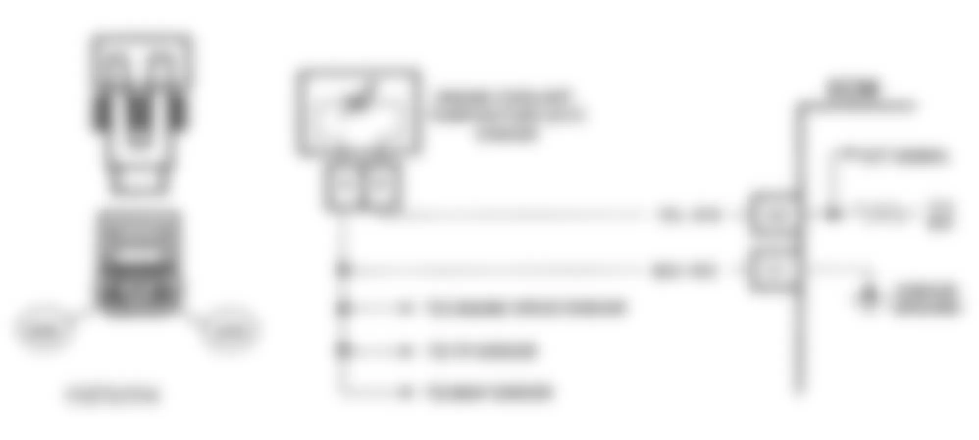
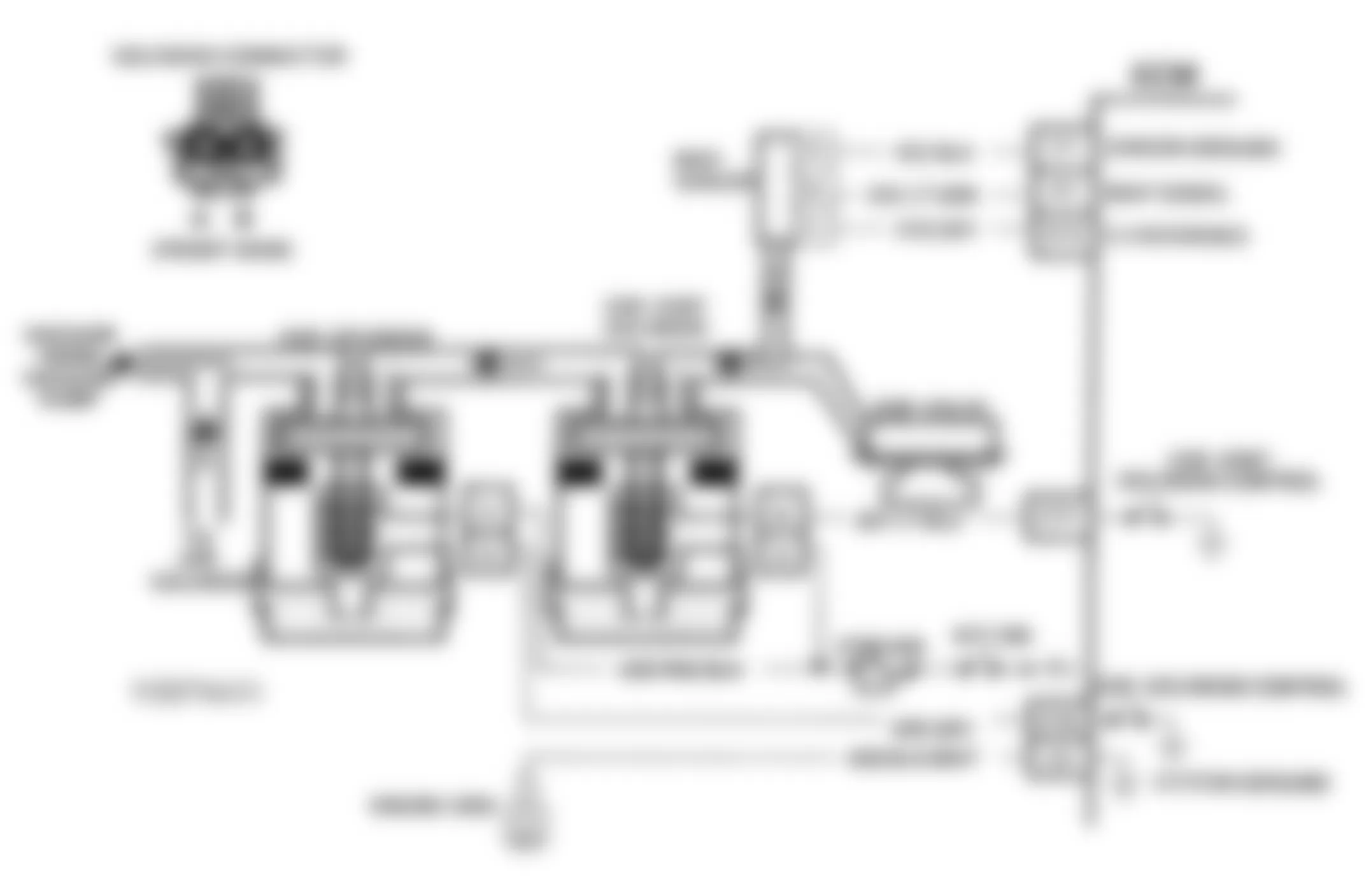
NOTE: The Assembly Line Data Link (ALDL) connector is also referred to as the Data Link Connector (DLC). This is the same connector.
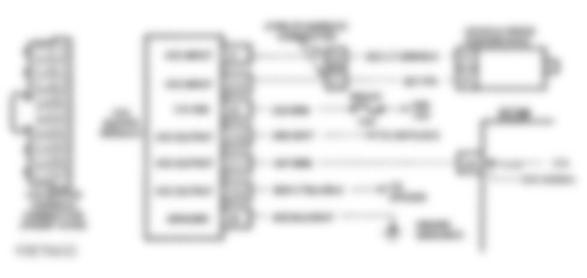
- With ignition on and engine off, connect a jumper wire between Data Link Connector (DLC) terminal "B" (diagnostic terminal) and terminal "A" (ground). See Fig. 1. The Diesel Electronic Control (DEC) system will enter diagnostic mode.
- In this mode, ECM will display DTC 12 by flashing the MIL once, followed by a short pause, then 2 flashes in quick succession.
- DTC 12 will be displayed 3 times. If no other codes are stored, DTC 12 will continue to flash until diagnostic terminal is ungrounded. To exit diagnostic mode, turn ignition off and remove jumper from DLC connector.
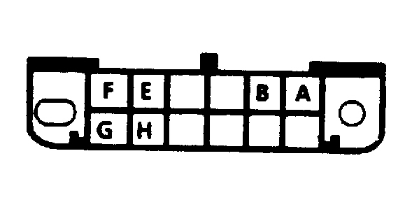
Fig. 1: GMC Yukon 1993 - Component Locations - Identifying DLC Connector Terminals
GMC Yukon 1993 - TROUBLE CODE IDENTIFICATION
NOTE: Trouble codes retrieved from ECM may be either engine or transmission related. Only engine-related codes are covered in this article. For transmission-related codes, see TESTS W/CODES - TRANSMISSION article in ENGINE PERFORMANCE section. See DIAGNOSTIC TROUBLE CODE (DTC) IDENTIFICATION table to determine if code is engine or transmission related.
- The DEC system codes indicate failure of a specific sensor and/or circuit. Sensor/circuit diagnosis may indicate replacement of ECM. DTC 51 indicates PROM is either improperly installed or has failed.
- DTC 52 indicates ECM has failed and must be replaced. If condition is still not corrected after replacing ECM, the following may be the cause:
- An incorrect ECM or PROM application may cause a malfunction, which may or may not set a code.
- The ECM connector may be the problem. Connector terminals may have to be removed from connector to be checked properly.
- PROM failure. Although the PROM rarely fails, it could be the cause of the problem.
- Replacement ECM may be faulty.
- Intermittent problem. Make a careful physical inspection of affected sensor/circuit.
- A shorted solenoid, coil relay, or harness may be the cause of ECM failure. Use Short Circuit Tester (J-34636) to check for short circuits.
GMC Yukon 1993 DIAGNOSTIC TROUBLE CODE (DTC) IDENTIFICATION
Code Probable Cause 12 (1) No Engine Speed Sensor Reference Pulse 14 (1) CTS Voltage Low (Sensor Or Signal Line Grounded) 15 (1) CTS Voltage High (Sensor, Connections, Or Wires Open) 16 (1) Transmission Output Speed Voltage Low 21 (1) TPS Voltage High (Open Circuit Or Misadjusted TPS) 22 (1) TPS Voltage Low (Circuit Grounded) 23 (1) TPS Not Calibrated (.25-1.3 Volts At Curb Idle) 24 (1) Vehicle Speed Sensor Circuit Open Or Grounded 28 Pressure Switch Manifold Range Circuit Open Or Shorted 31 (1) MAP Voltage Low (Circuit Open Or Shorted To Ground) 32 (1) EGR Error (Improper Vacuum Signal) 33 (1) MAP Voltage High (Circuit Open Or Shorted To Ground) 39 TCC Stuck Off (Faulty TCC Solenoid) 51 (1) Improperly Installed/Faulty PROM 52 (1) ECM Fault 53 (1) Voltage Reference Overload 58 TTS High Temperature (Sensor Or Signal Line Grounded) 59 TTS Low Temperature (Sensor, Connections, Or Wires Open) 68 Overdrive Ratio Error (Engine RPM Greater Than Input Speed) 73 Force Motor Commanded Amperage Differs From Return 75 System Voltage Low (Charging System Problem) 81 QDM Solenoid "B" Monitored Voltage Differs From Commanded 82 QDM Solenoid "A" Monitored Voltage Differs From Commanded 83 QDM TCC Monitored Voltage Differs From Commanded 85 Undefined Gear Ratio (Input Or Output Sensor Failure) 86 Shift Solenoid "B" Stuck On (Commanded Gear Not Engaged) 87 Shift Solenoid "B" Stuck Off (Commanded Gear Not Engaged)
(1) Code is engine related. Engine related codes are covered in this article. For information on transmission related codes, see TESTS W/CODES - TRANSMISSION article in this section.
GMC Yukon 1993 - CLEARING TROUBLE CODES
CAUTION: When battery is disconnected, vehicle computer and memory systems may lose memory data. Driveability problems may exist until computer systems have completed a relearn cycle. See COMPUTER RELEARN PROCEDURES article in the GENERAL INFORMATION section before disconnecting battery.
NOTE: To prevent ECM damage, ensure ignition switch is in OFF position when disconnecting or reconnecting power to ECM.
Trouble codes should be cleared after repairs have been completed. Also, some diagnostic charts require codes to be cleared before using diagnostic chart. To clear codes, remove power to ECM for 30 seconds by either disconnecting battery cable and ECM pigtail to battery, or removing ECM "B" fuse.
If no hard fault codes are present (only intermittent codes exist), proceed to TESTS W/O CODES article in this section for intermittent diagnostic procedures.
GMC Yukon 1993 - ECM LOCATION
The ECM is located under passenger's seat riser ("G" Series), or behind right side of dash (all other models).
GMC Yukon 1993 - SPECIAL TOOLS (DIAGNOSTIC)
Special scan testers, plugged into the DLC connector, may be used to read trouble codes, and check voltages in system on serial data line. These testers can save a great deal of time. For additional information, see owner's manual included with tester.
GMC Yukon 1993 - TEST EQUIPMENT
A tachometer, test light, Digital Volt-Ohmmeter (DVOM) with a minimum 10-megohm input impedance, a vacuum gauge, and jumper wires are required to test and diagnose Diesel Electronic Control (DEC) system. A scan tester may also be used to access data parameters. Tester will supply a visual reading of most inputs, and some outputs, to ECM.
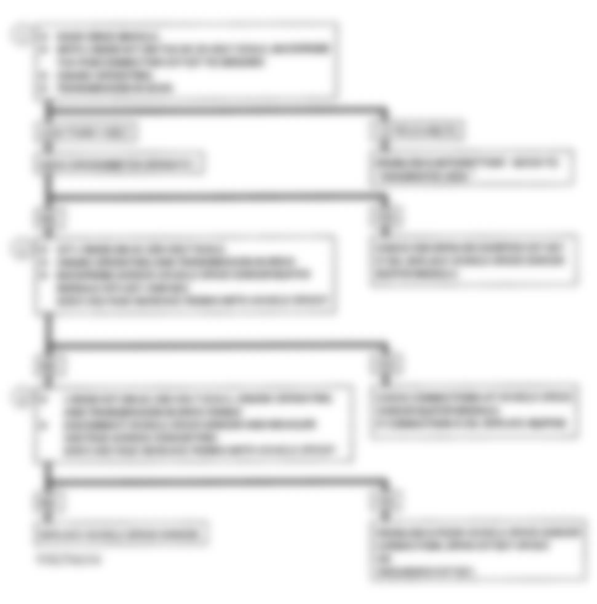
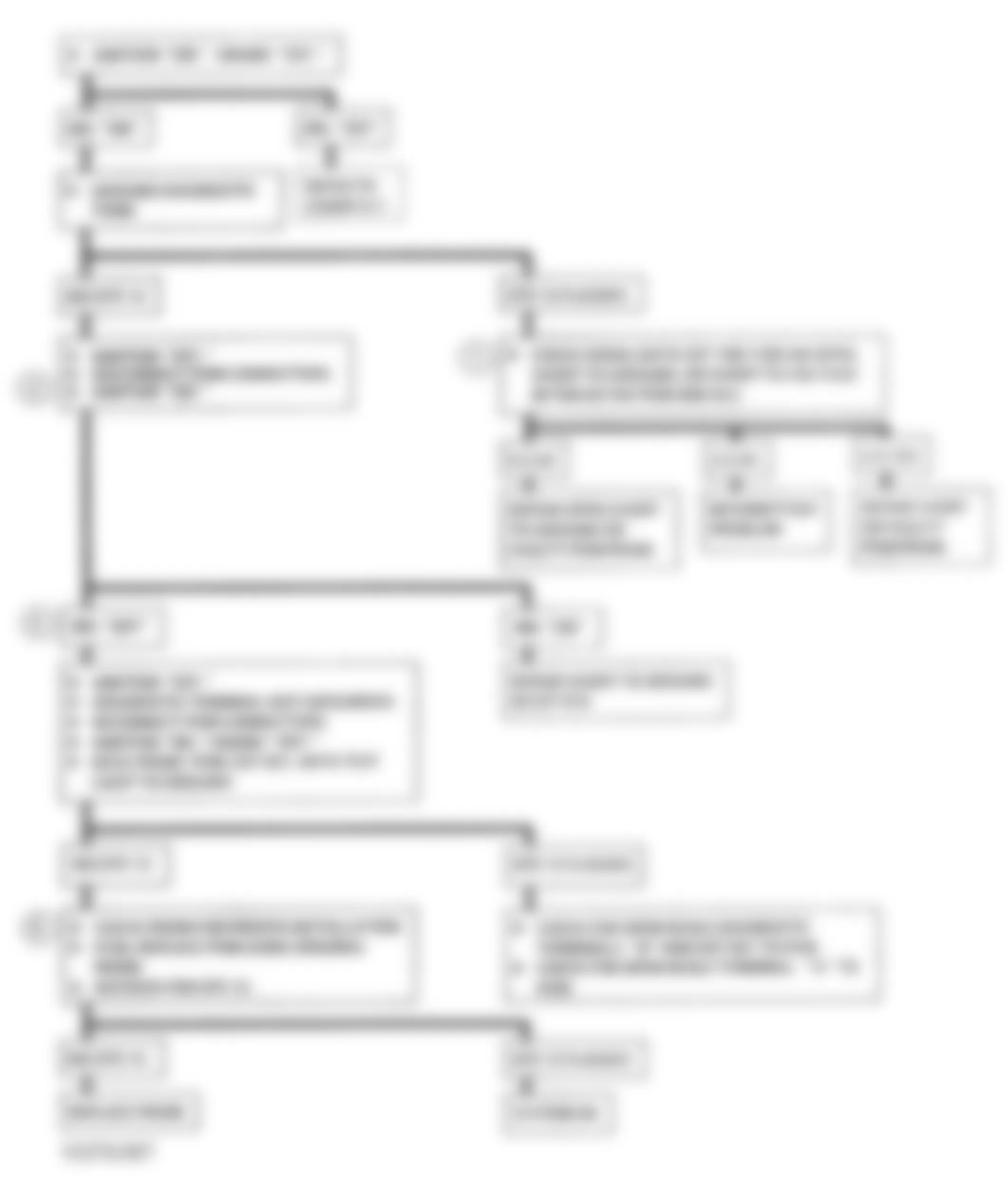
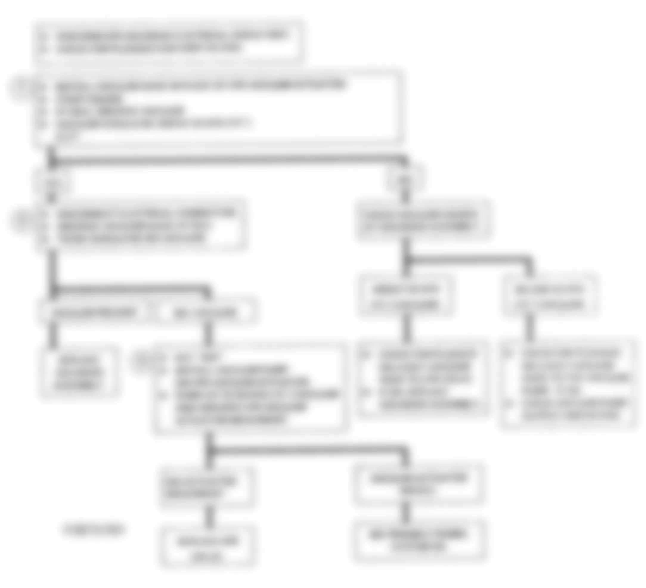
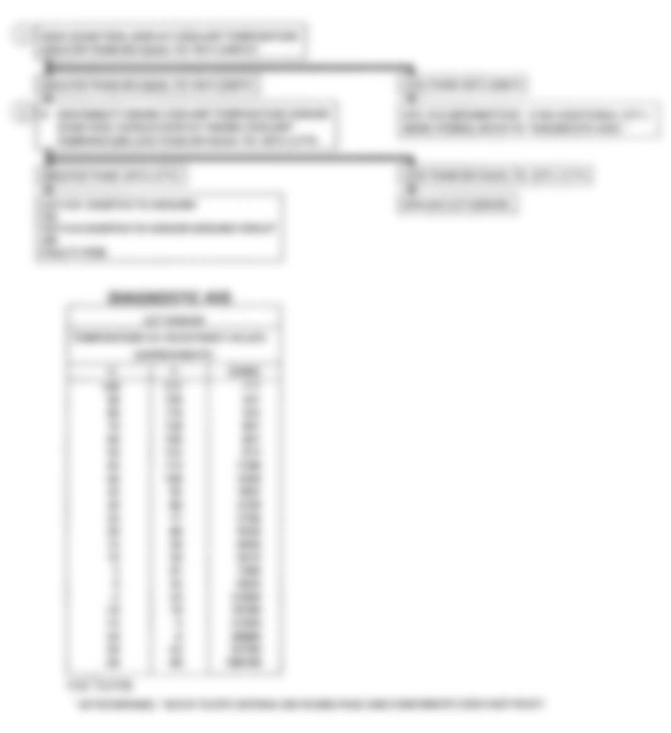
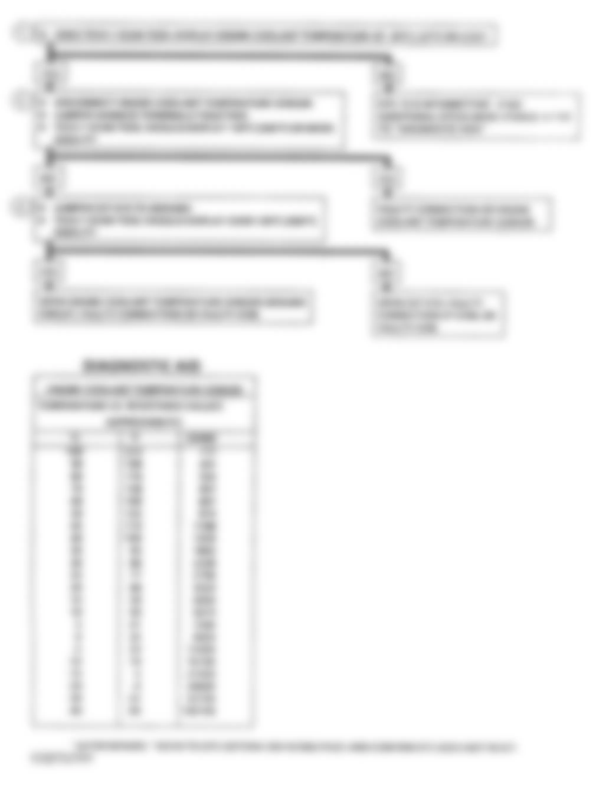
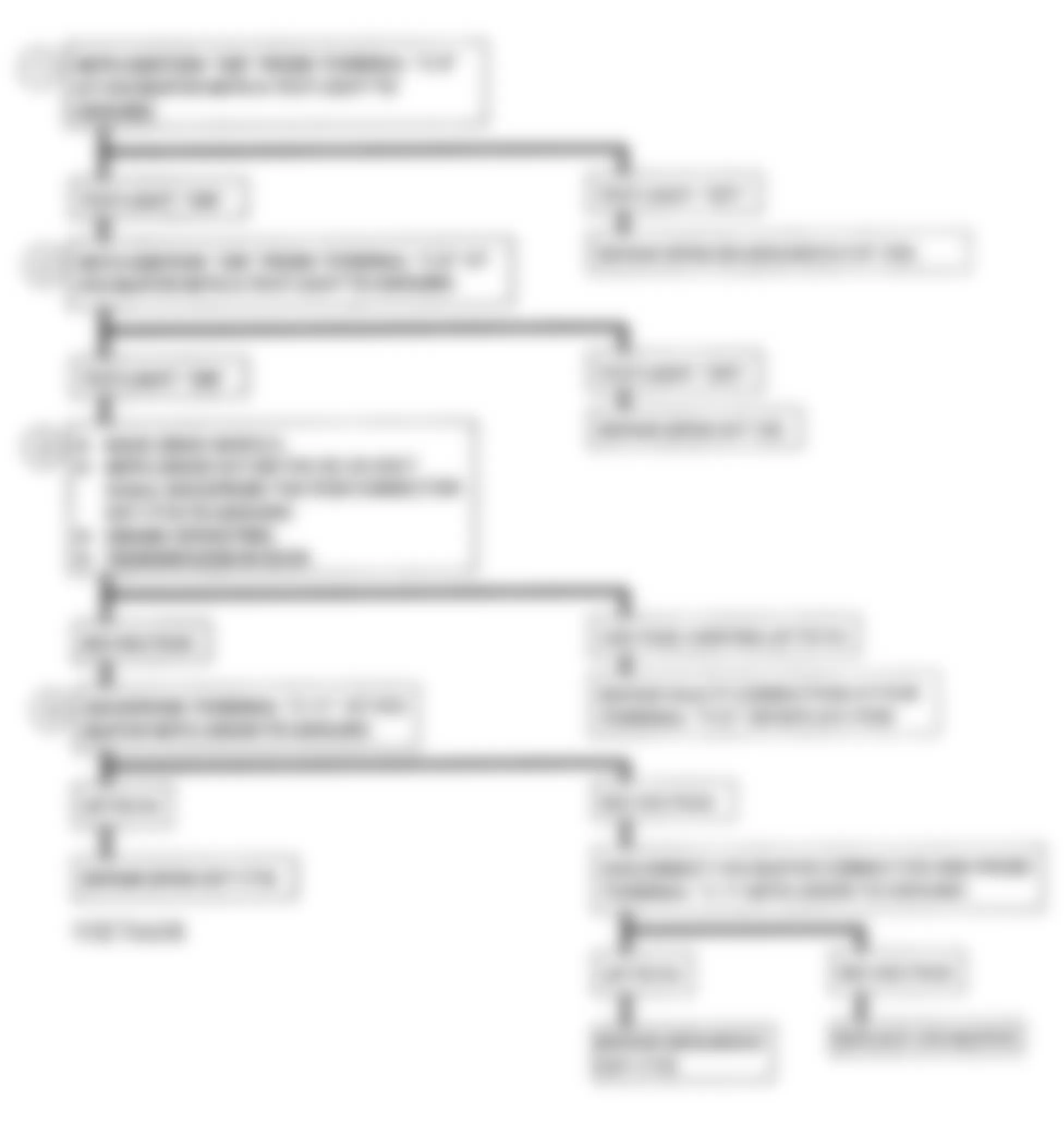
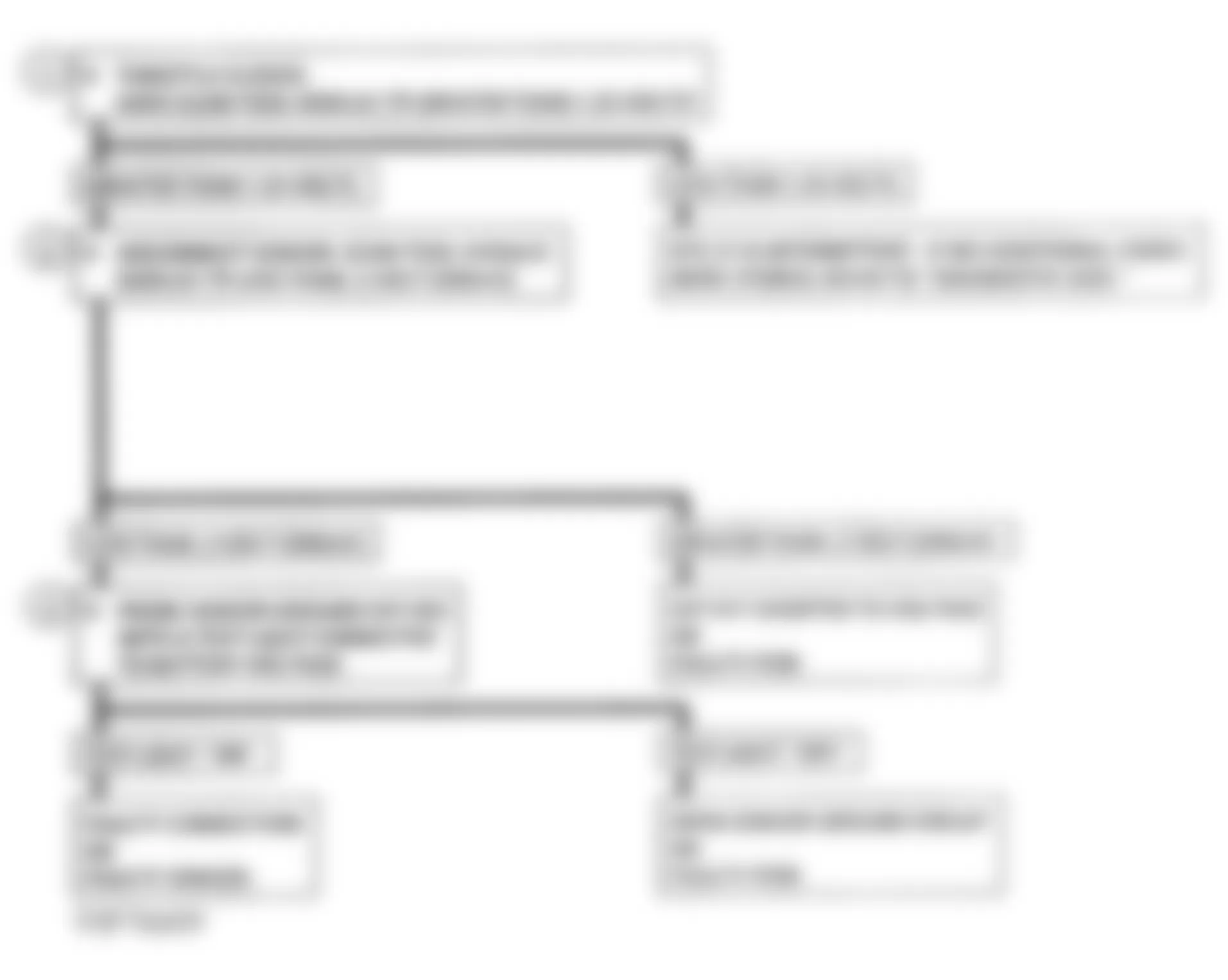
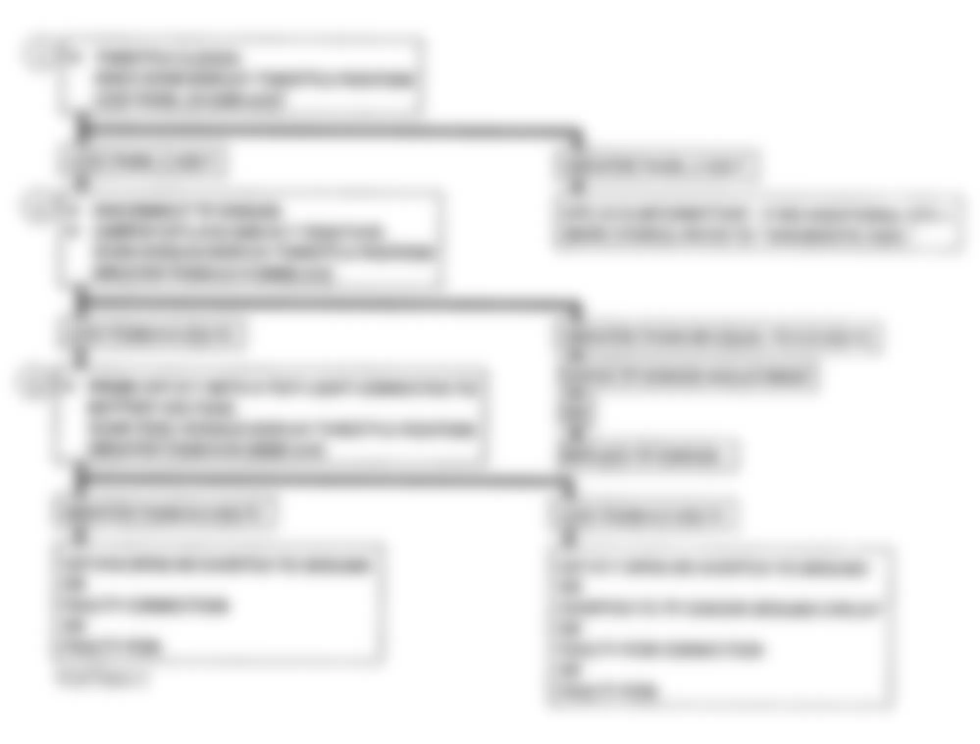
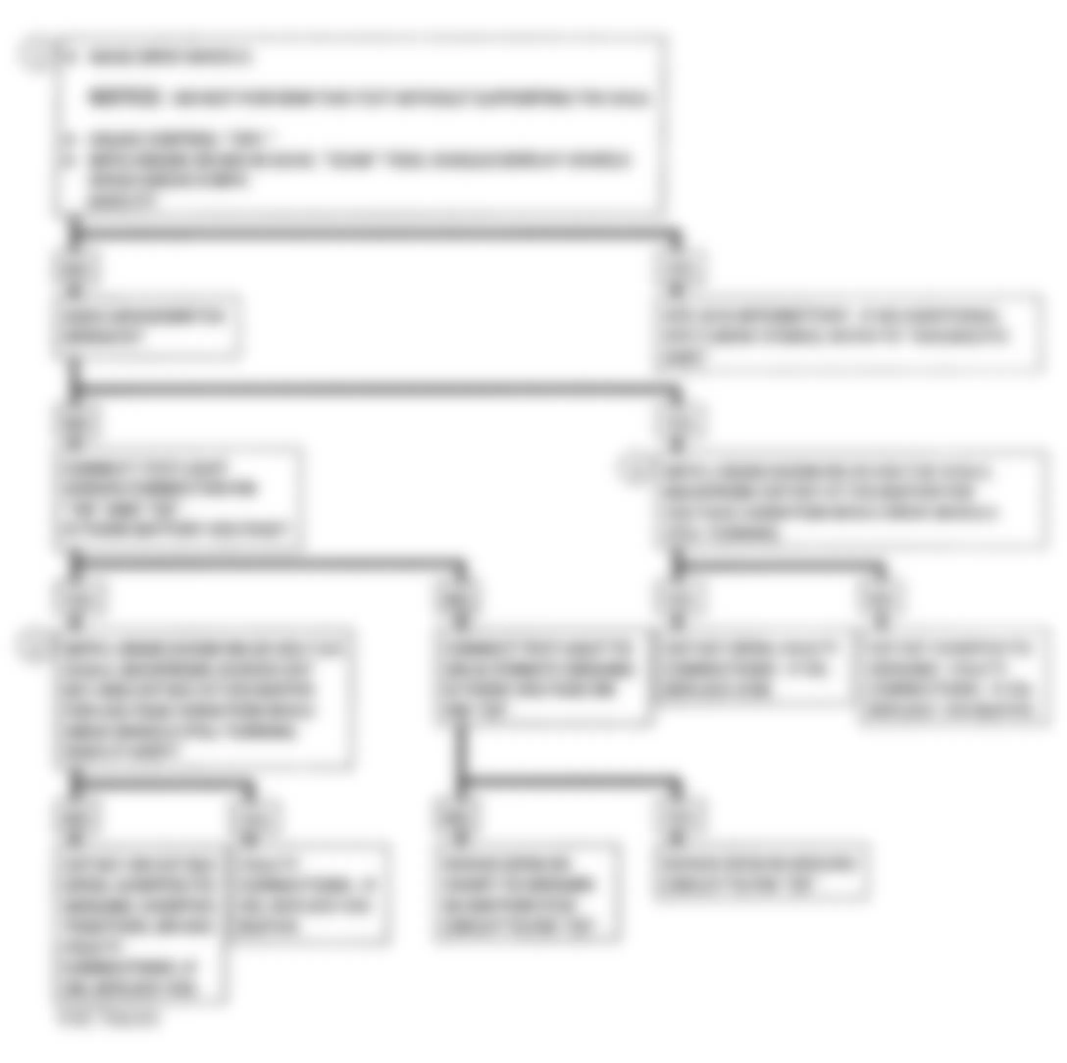
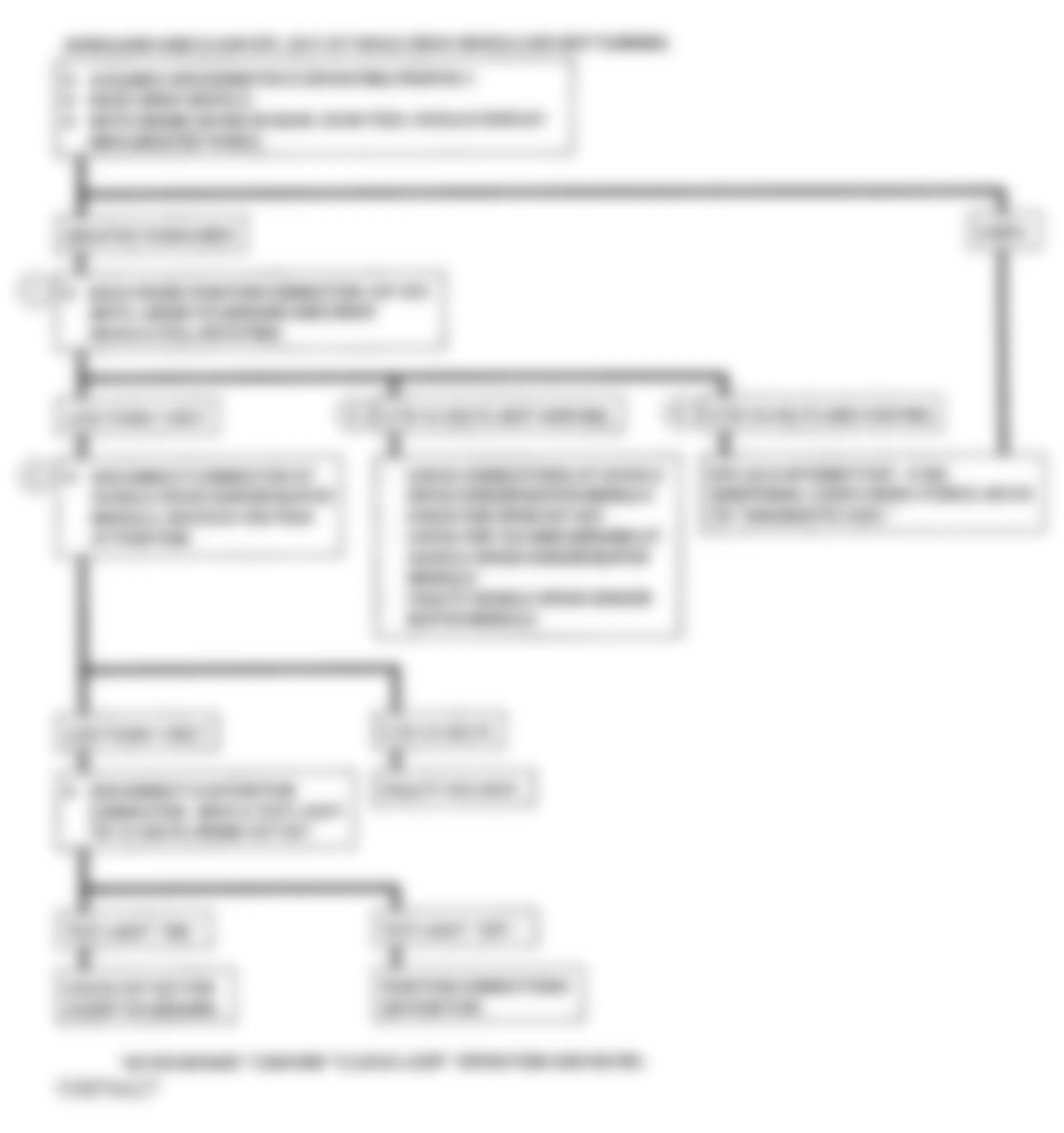
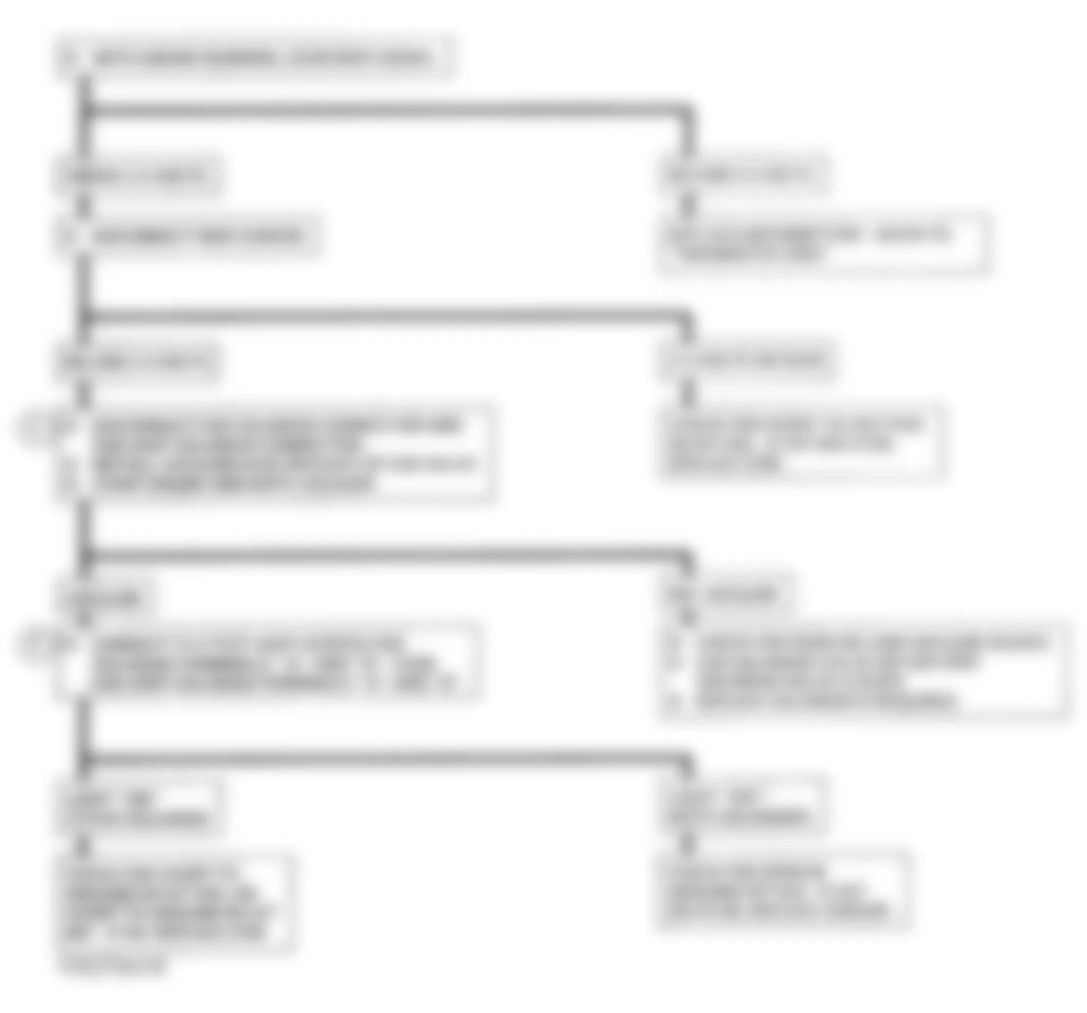
GMC Yukon 1993 - DIAGNOSTIC CHARTS DIAGNOSTIC SYSTEM CHECK (WITH AUTOMATIC TRANSMISSION)
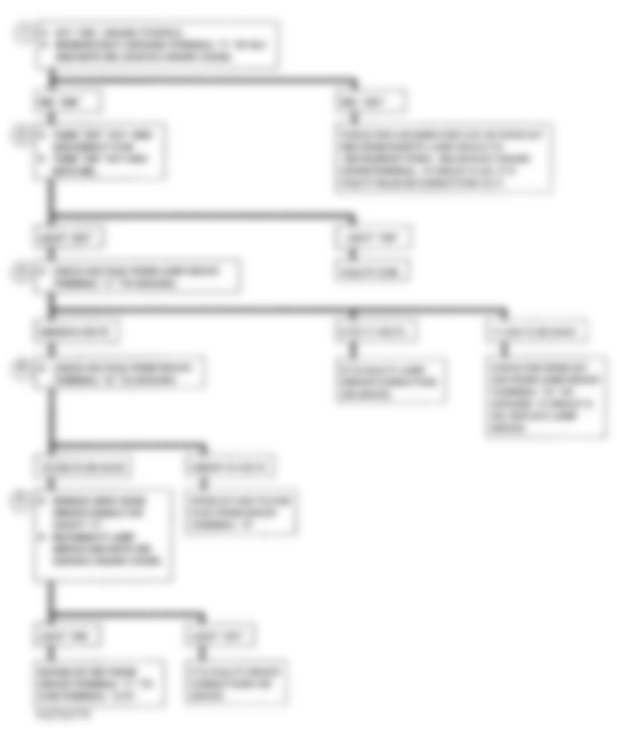
The diagnostic system check is an organized approach to identifying a problem created by a control module system malfunction. This is the starting point for any driveability complaint diagnosis, as it directs technician to the next logical step in diagnosis, helps reduce diagnostic time and prevents the unnecessary replacement of good parts.
NOTE: Test numbers refer to numbers on diagnostic chart.
- This tests MIL operation. With ignition on and engine off, light should be on.
- No MIL at this point indicates there is a problem with MIL control circuit or ECM control of that circuit.
- This tests ability of ECM to control MIL light. With diagnostic terminal grounded, MIL should flash DTC 12 three times, followed by any other DTC stored in memory. A ECM or PROM error may result in the inability to flash DTC 12.
- Use TECH 1 to aid in diagnosis (to check if serial data is available). If a PROM error is present, the ECM may have been able to flash DTC 12 or 15, but not enable serial data.
- This step will isolate if customer complaint is an MIL or driveability problem with no MIL displayed. See DIAGNOSTIC TROUBLE CODE (DTC) IDENTIFICATION table under TROUBLE CODE IDENTIFICATION, to determine if code is valid. An invalid DTC may be the result of a faulty scan tester, PROM or ECM.
- If all scan data values are okay, check engine mechanical condition.
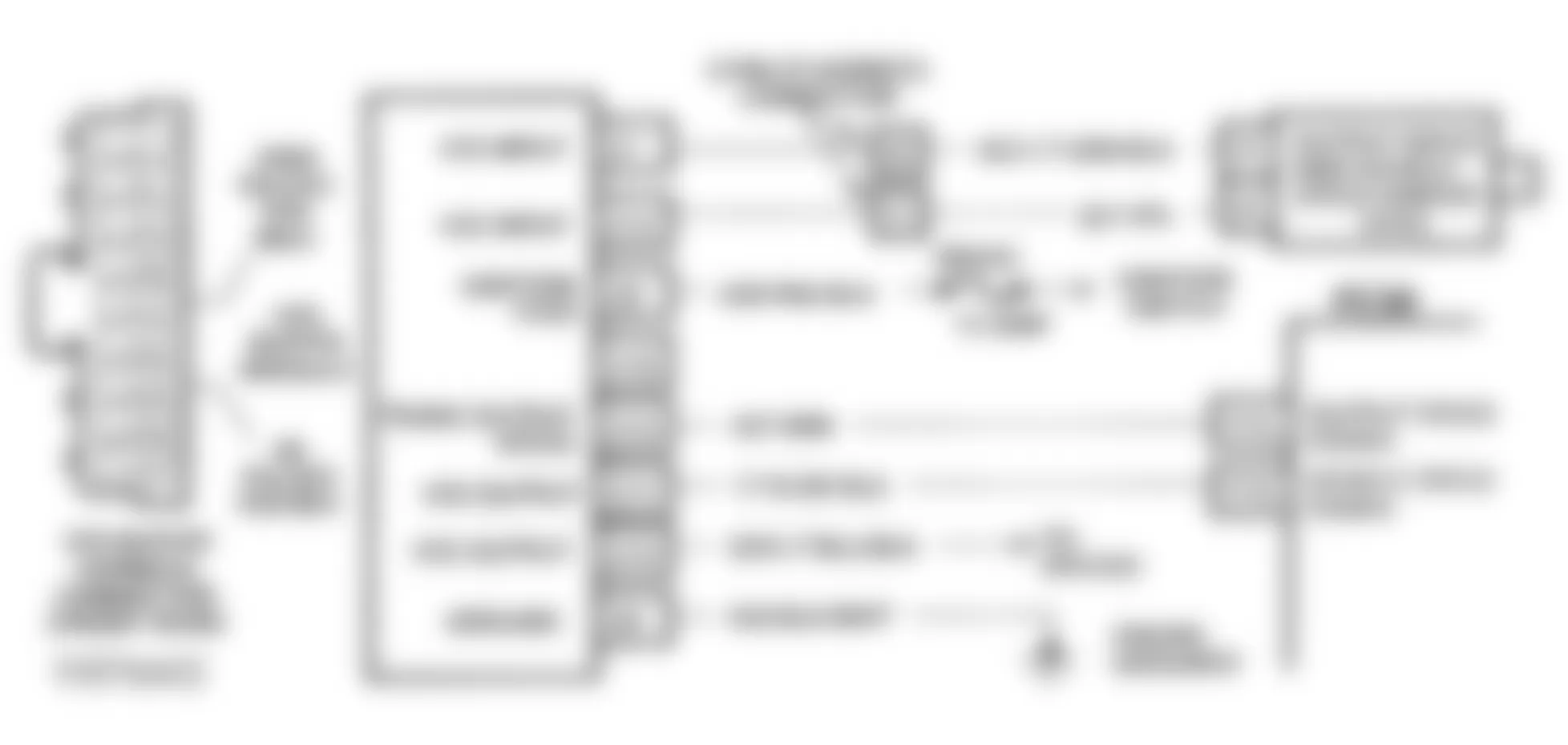
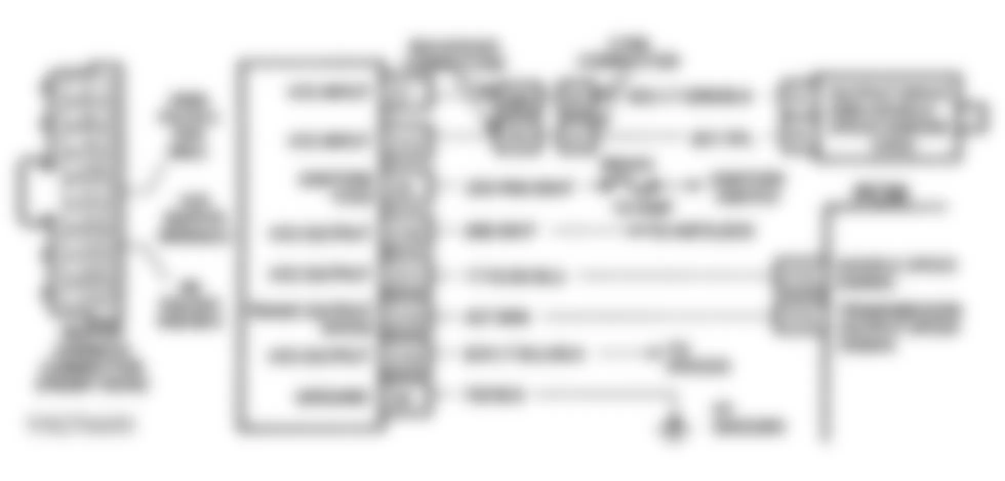
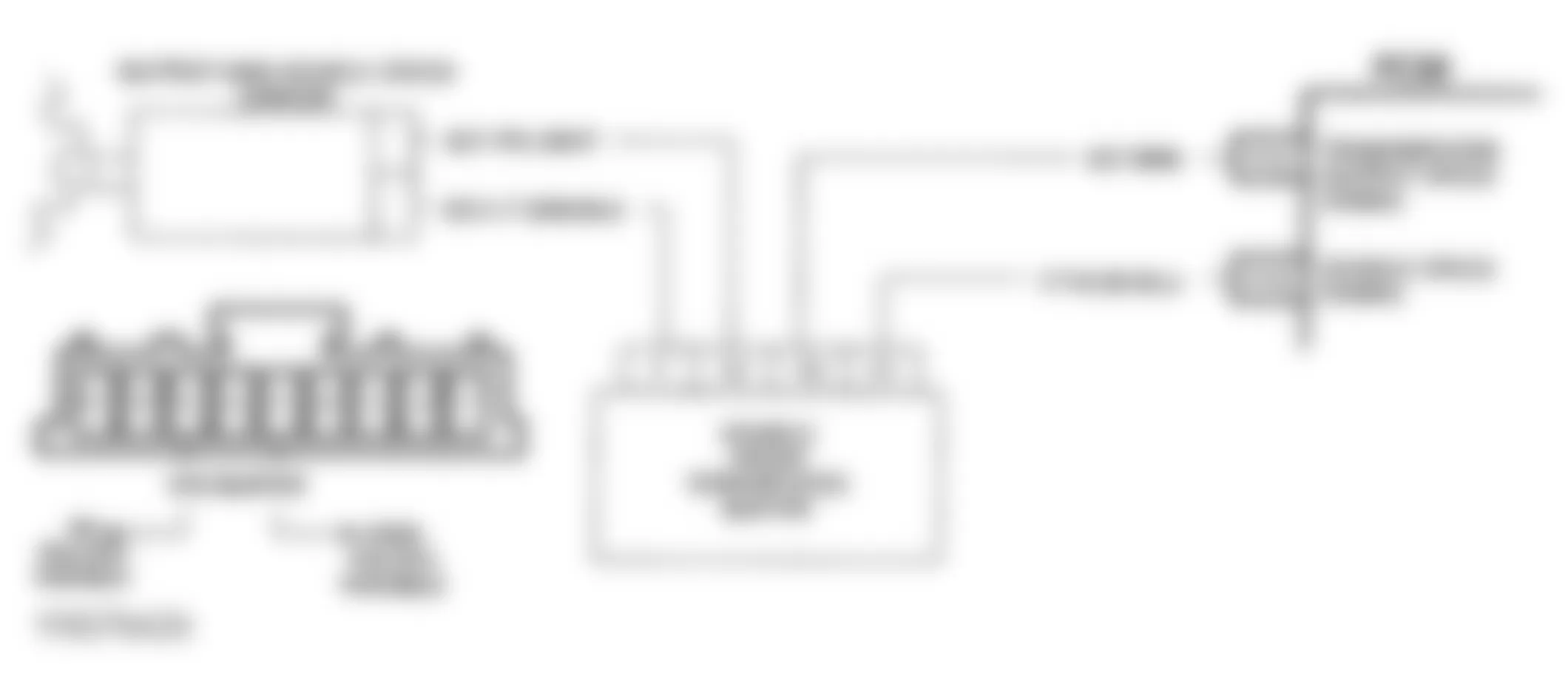
Fig. 2: GMC Yukon 1993 - Component Locations - Schematic, Diag. System Check A/T ("C" & "K" Series)

Fig. 3: GMC Yukon 1993 - Component Locations - Schematic, Diag. System Check A/T ("G" Series)

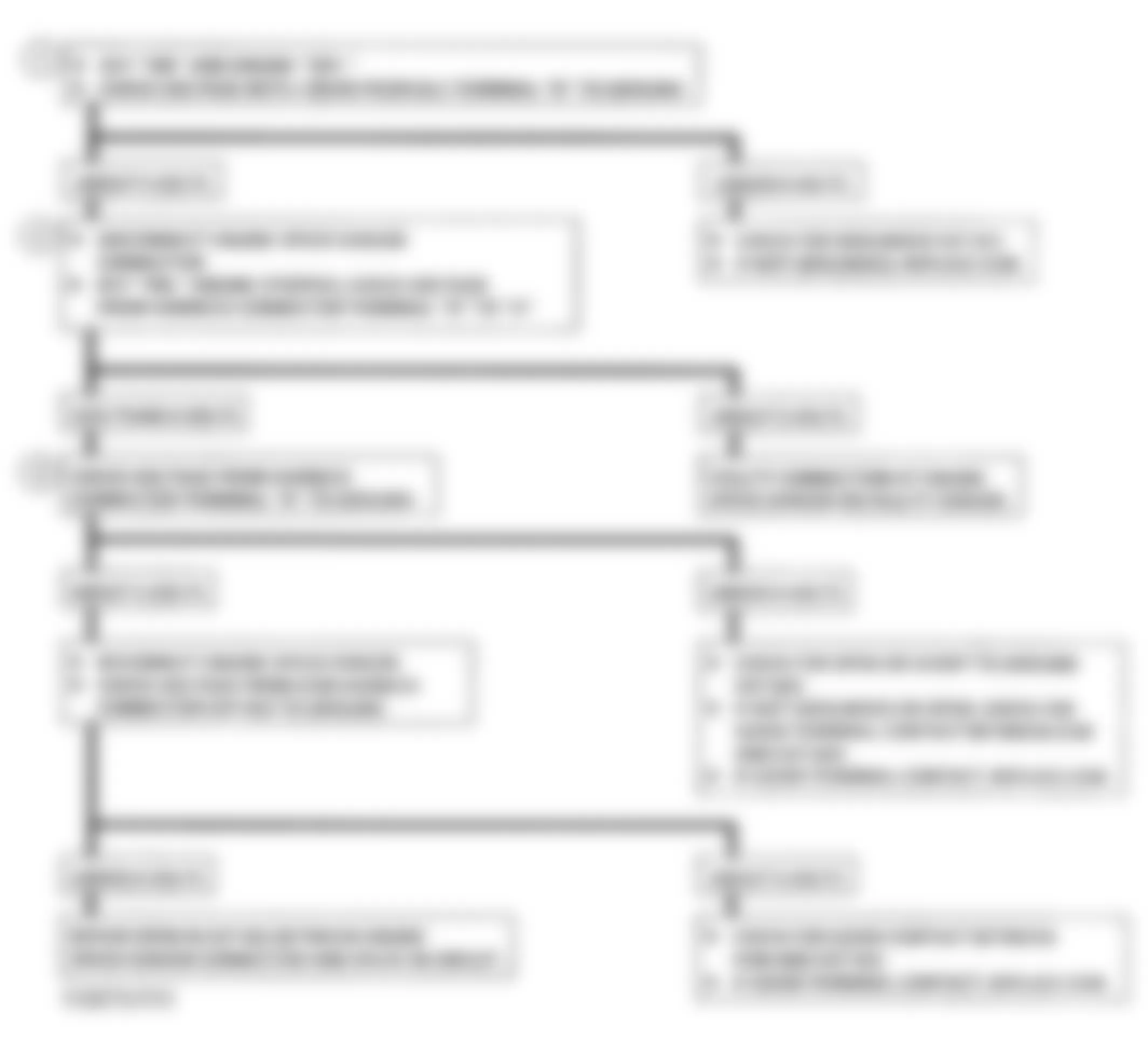
Fig. 4: GMC Yukon 1993 - Component Locations - Flowchart, System Check A/T
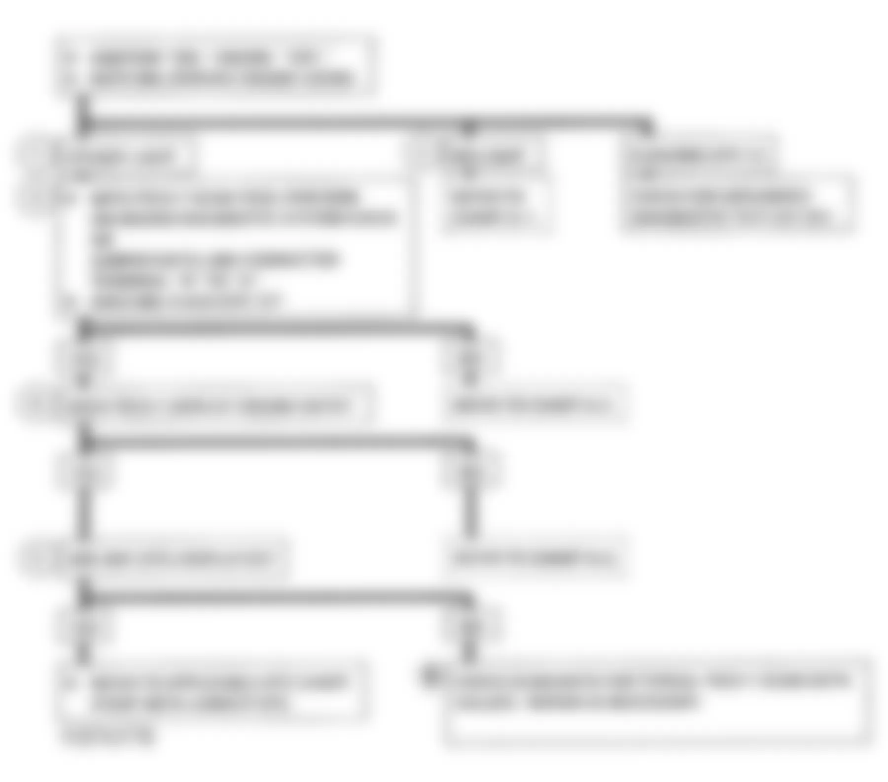
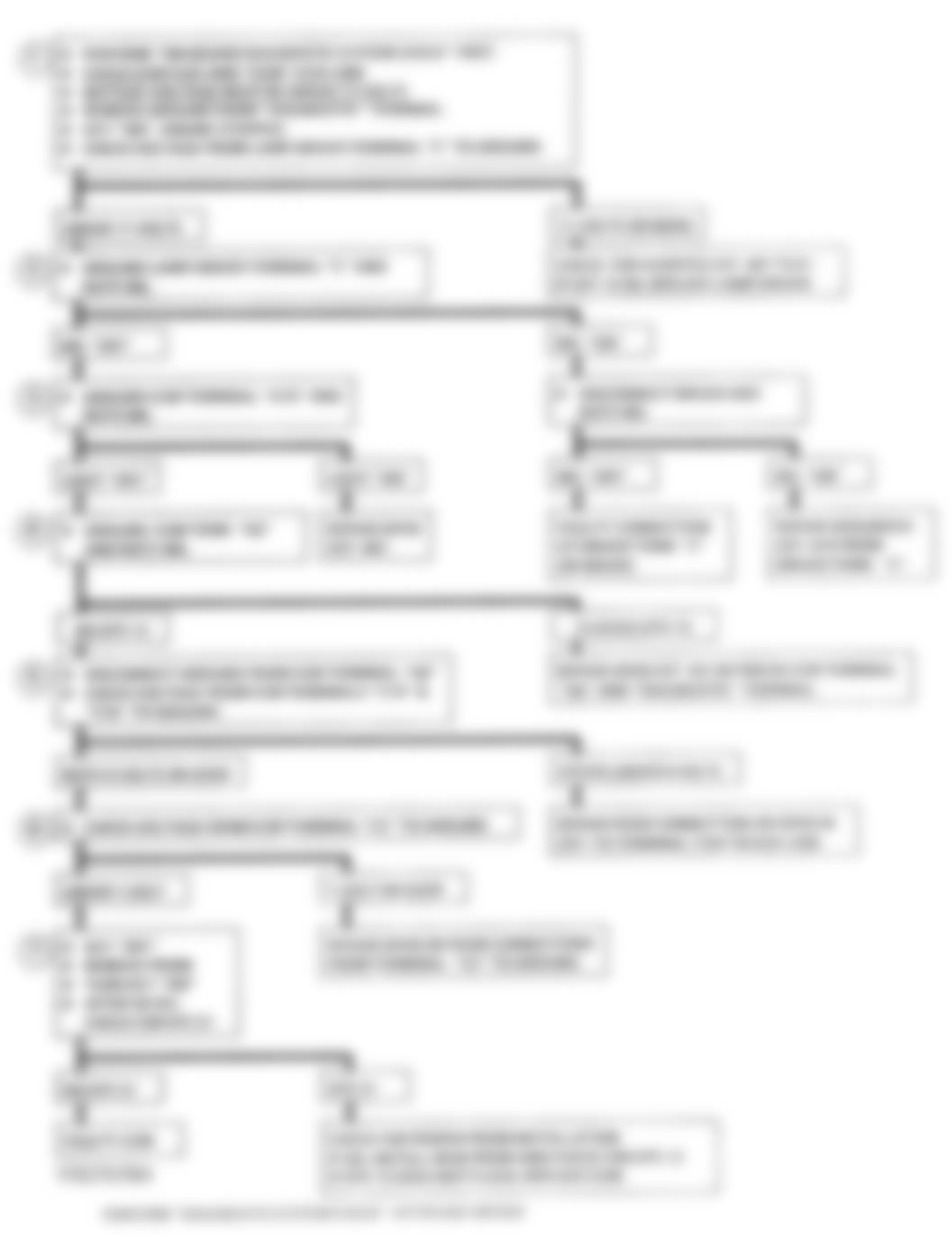
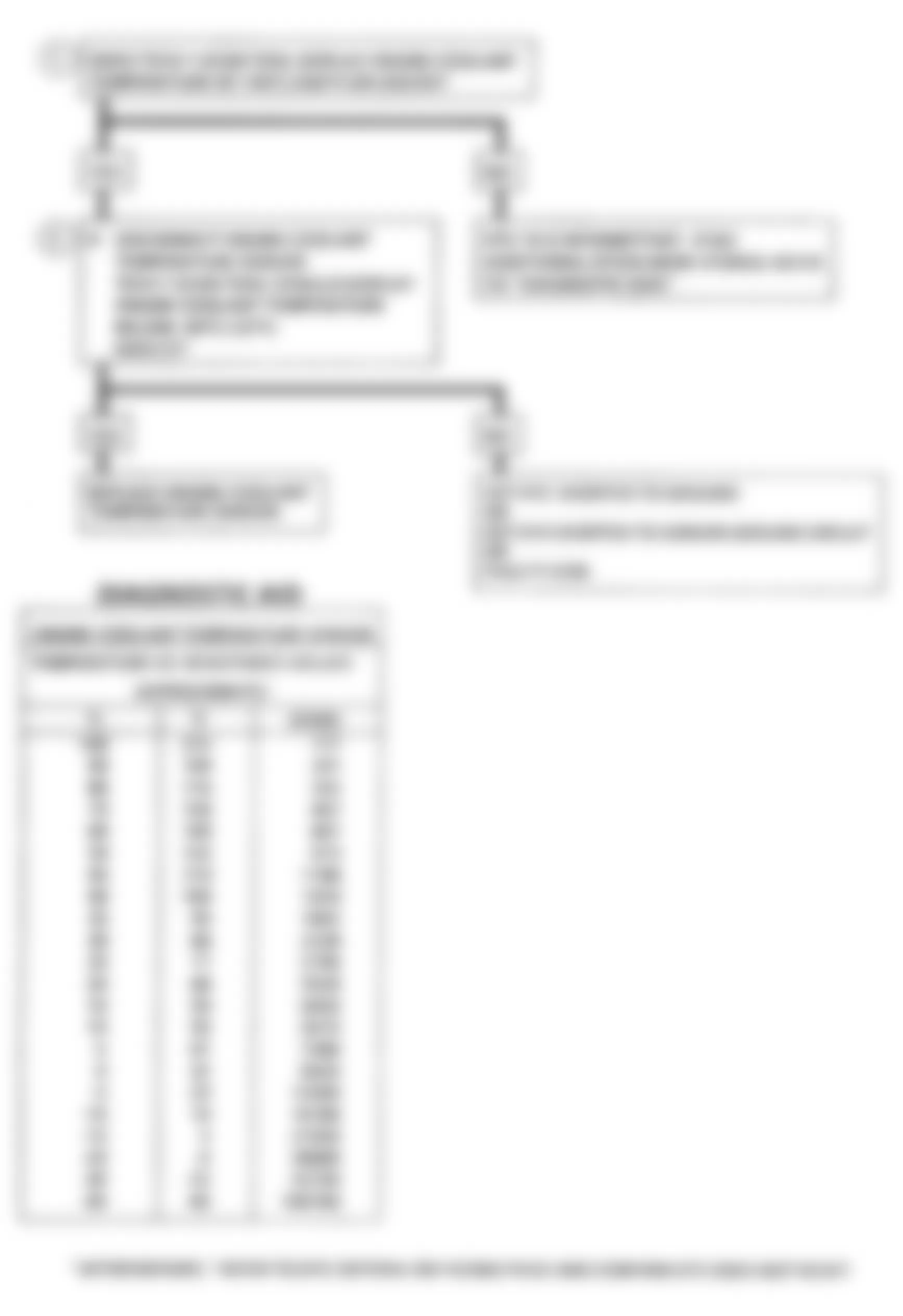
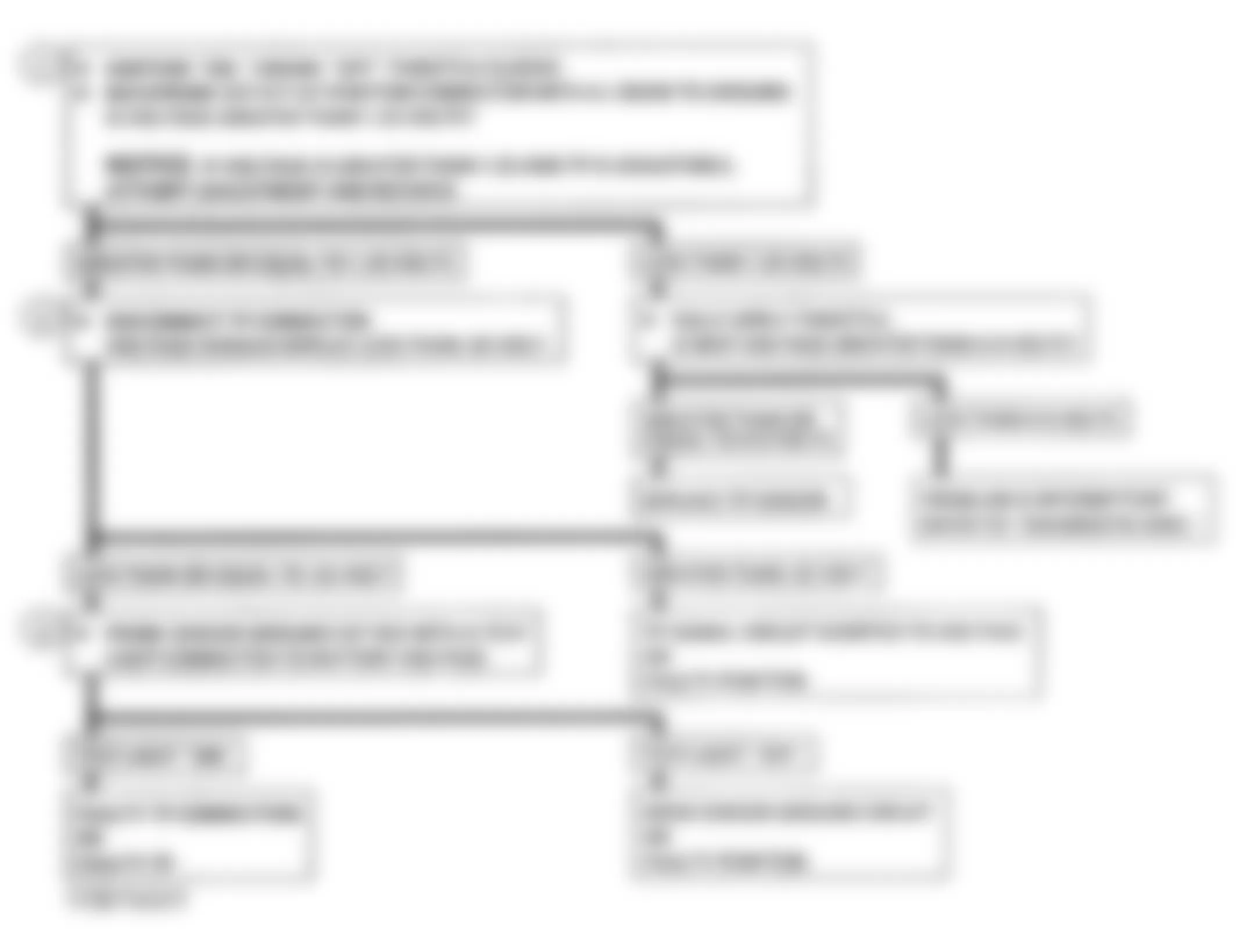
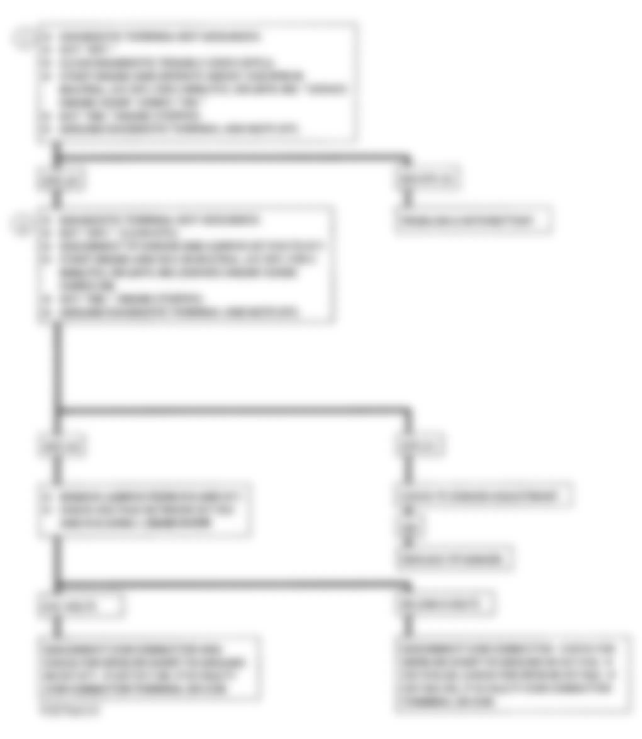
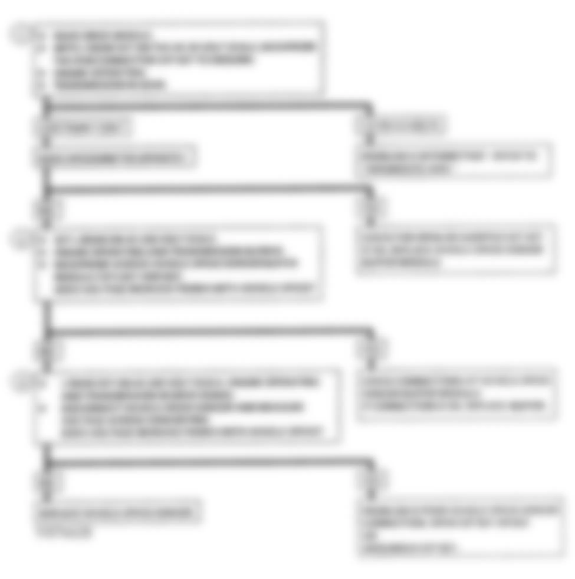
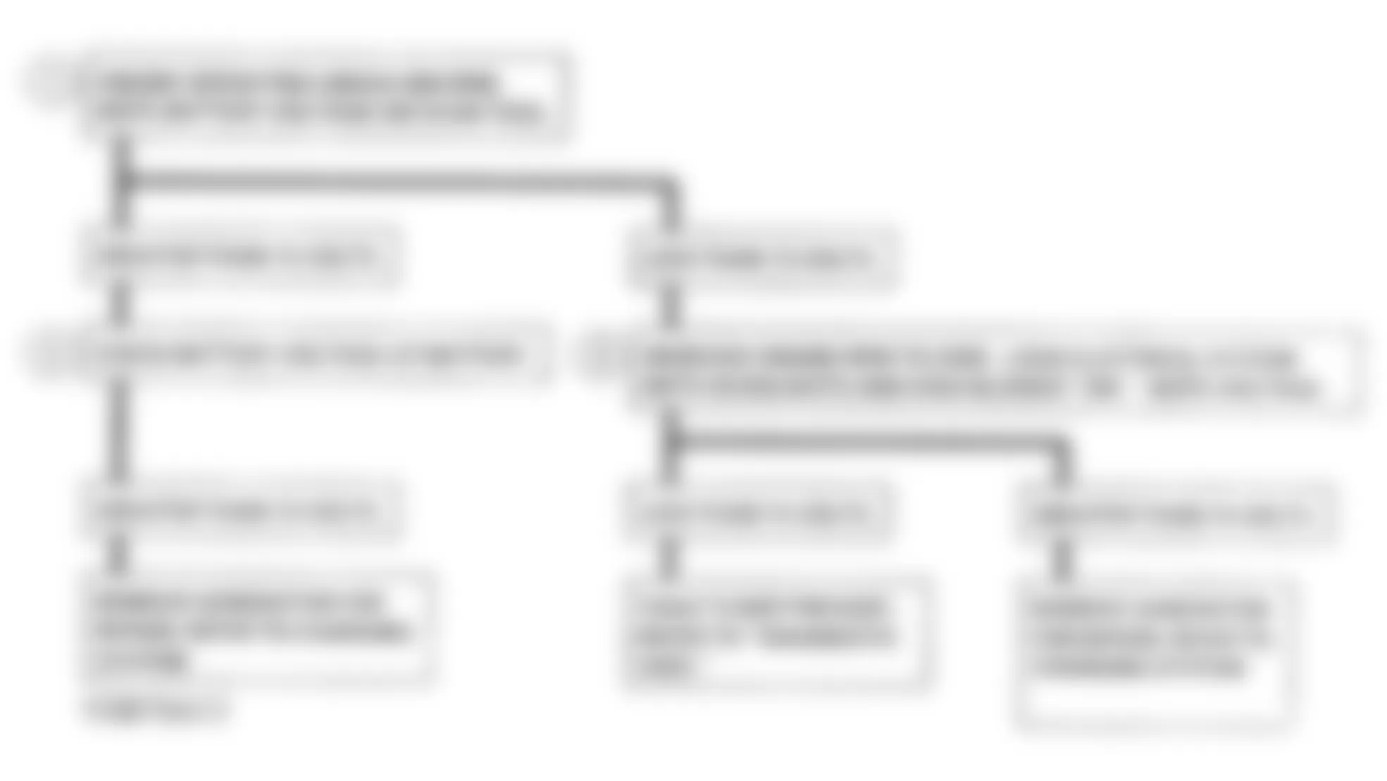
GMC Yukon 1993 - DIAGNOSTIC SYSTEM CHECK (WITH MANUAL TRANSMISSION)
The ECM provides diagnostic logic to detect faults in systems that the ECM controls or monitors. When ECM recognizes a fault, it turns on MIL and stores codes. If condition is corrected, MIL will go off. ECM recognizes errors in engine speed and EGR vacuum, as well as electrical faults involving 5-volt reference circuit. ECM controls the following:
- Exhaust Gas Recirculation (EGR).
- Exhaust Pressure Regulation (EPR).
- System diagnosis.
- Cold advance and glow plugs.
To allow proper engine control, ECM monitors the following inputs:
- Engine RPM.
- Manifold Absolute Pressure (MAP) signal used to monitor EPR vacuum.
- Throttle Position (TP) sensor signal.
- Vehicle Speed Sensor (VSS) signal.
- Engine Coolant Temperature (ECT) sensor signal.
Begin all diagnosis with diagnostic system check. After any DEC system repair, repeat diagnostic system check.
NOTE: Test numbers refer to numbers on diagnostic chart.
- This tests MIL operation. With ignition on and engine off, light should be on.
- Grounding Data Link Connector (DLC) terminal "B" allows ECM to flash DTC 12 and any stored codes. Light must flash on and off to be considered a proper code. If light just goes from bright to dim, it is not considered a code.
- If a driveability problem exists, check engine mechanical condition.
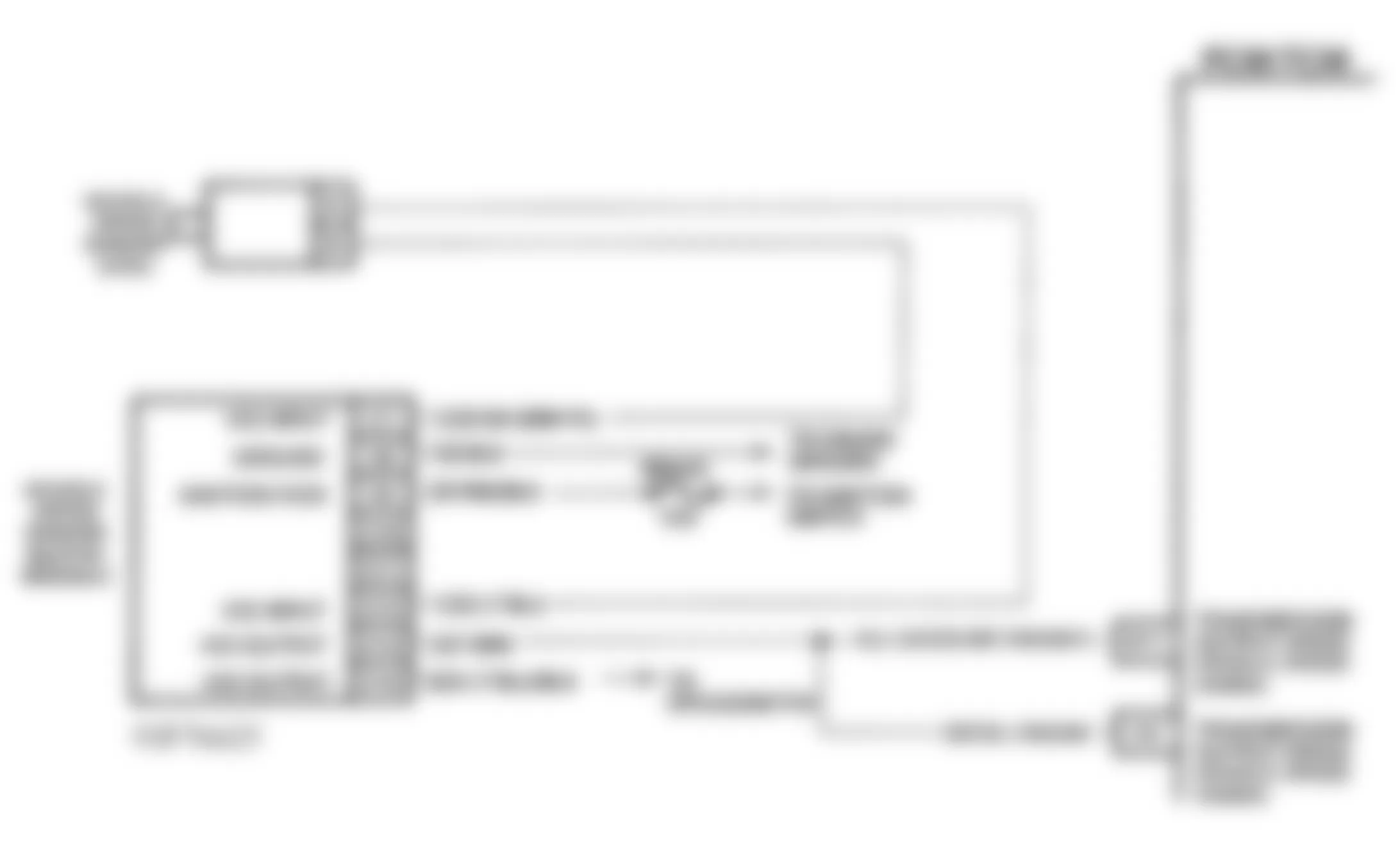
Fig. 5: GMC Yukon 1993 - Component Locations - Schematic, Diagnostic System Check M/T

Fig. 6: GMC Yukon 1993 - Component Locations - Flowchart, Diagnostic System Check M/T
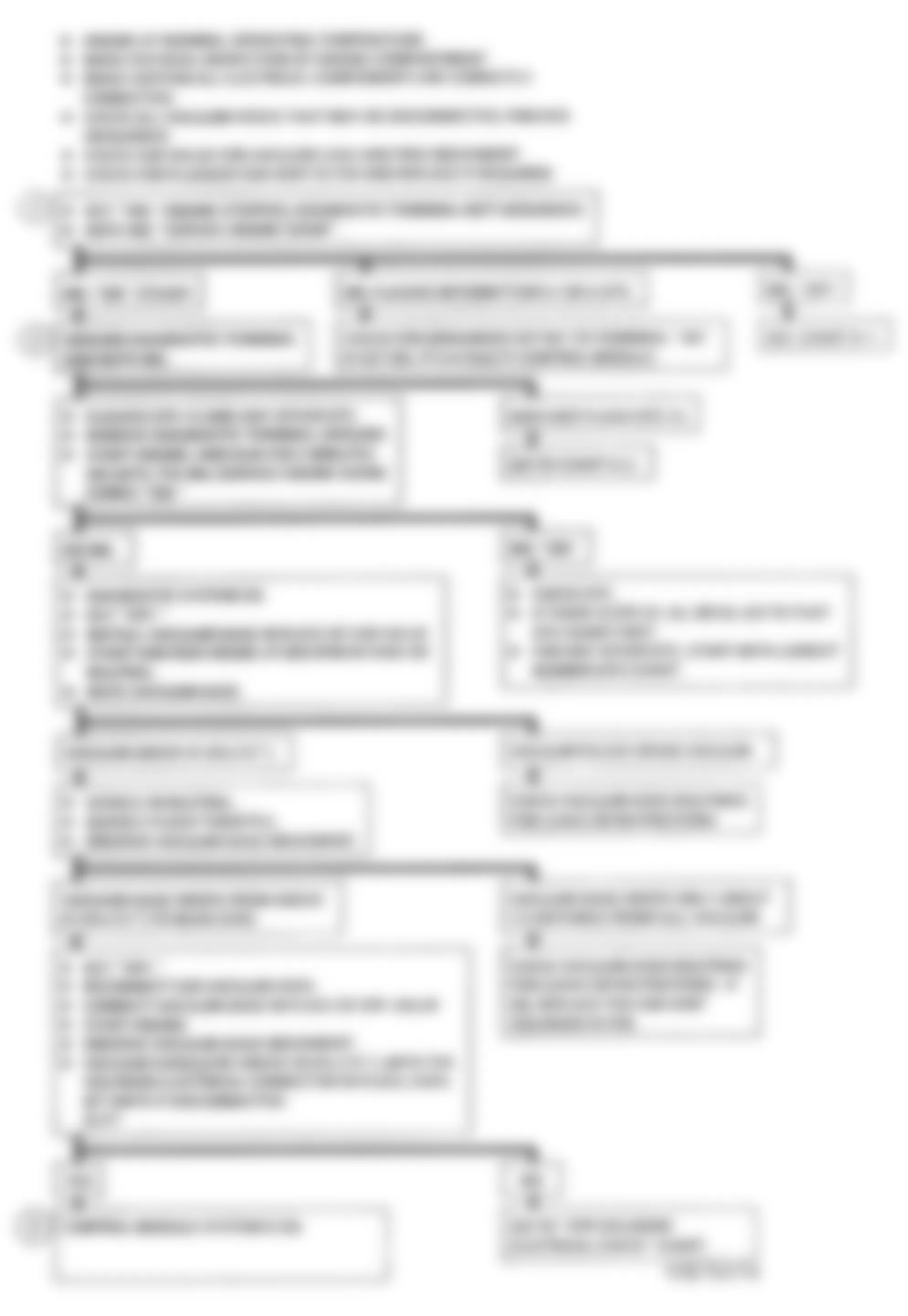
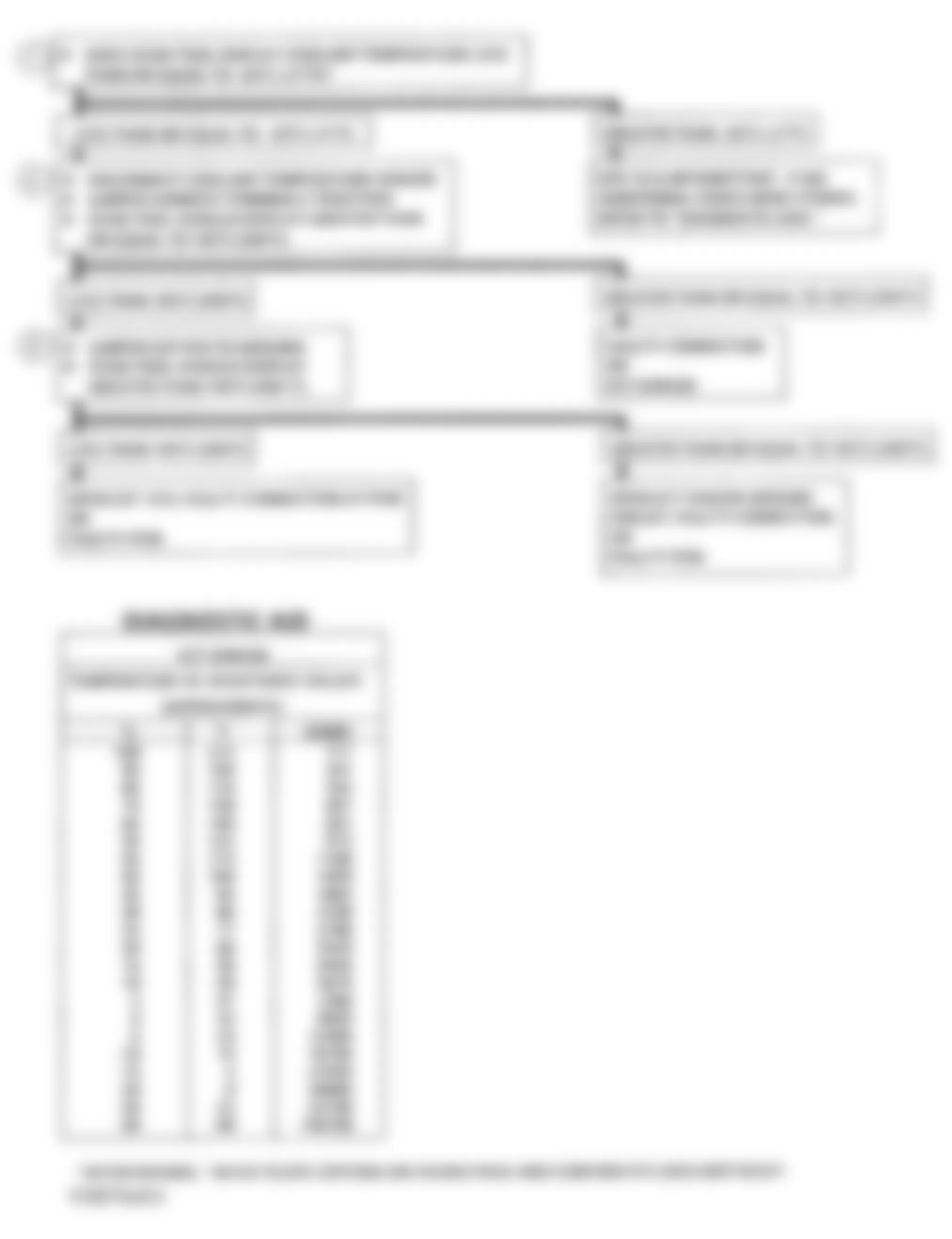
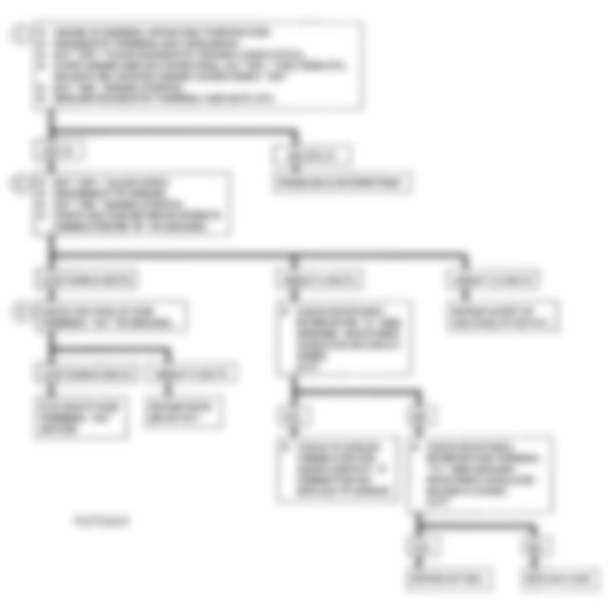
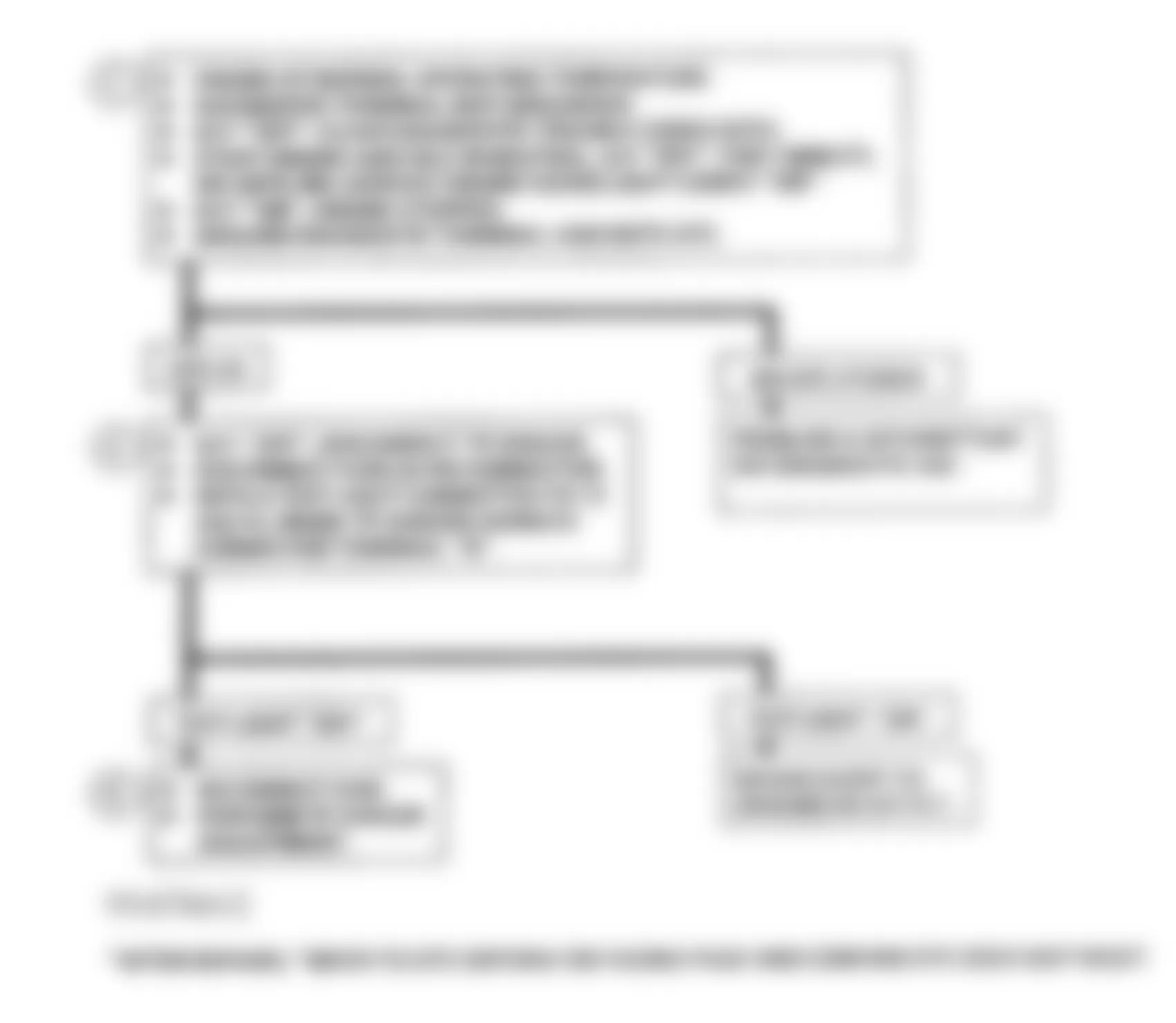
GMC Yukon 1993 - CHART A-1, NO MIL (SERVICE ENGINE SOON) LIGHT (WITH A/T)
MIL should be on when engine is off and ignition is on. Switched battery voltage is supplied to MIL. The ECM turns light on by providing a ground path through circuit No. 419.
NOTE: Test numbers refer to numbers on diagnostic chart.
- If fusible link is blown, see WIRING DIAGRAMS article in this section for complete circuit.
- Using a test light connected to 12 volts, probe each of the system ground circuits to ensure a good ground is present. See PIN VOLTAGE CHARTS article in this section.
GMC Yukon 1993 - Diagnostic Aids
If engine functions properly, check for a burned out bulb, blown gauges fuse, or circuit No. 419 open. If engine cranks but will not start, check for blown fusible link and for open circuit No. 440 to fuel pump relay.
Fig. 7: GMC Yukon 1993 - Component Locations - A-1, Schematic, No MIL - A/T ("C" & "K" Series)
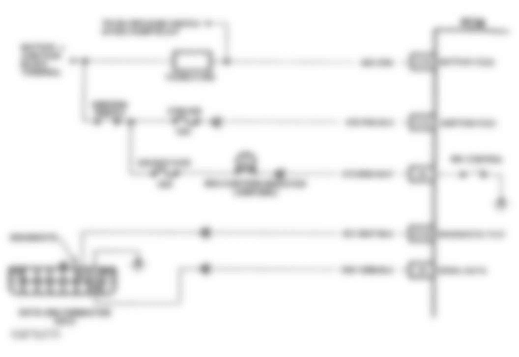
Fig. 8: GMC Yukon 1993 - Component Locations - A-1, Schematic, No MIL - A/T ("G" Series)
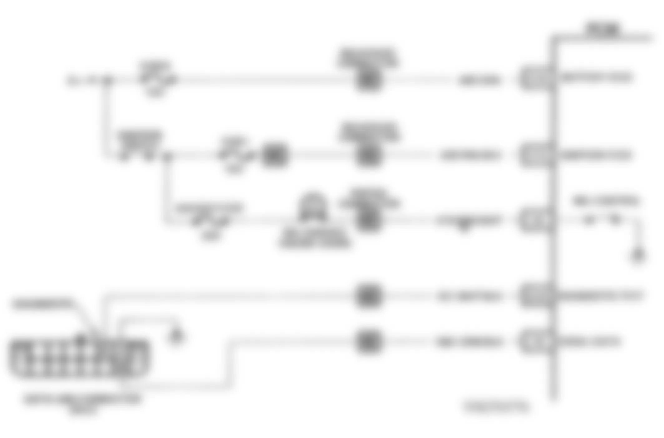
Fig. 9: GMC Yukon 1993 - Component Locations - A-1, Flowchart, No MIL, A/T

GMC Yukon 1993 - CHART A-1, NO MIL (SERVICE ENGINE SOON) LIGHT (WITH M/T)
When engine is started, ECM grounds terminal A10 to turn off MIL. When DLC terminal "B" is grounded, ECM alternately grounds and opens terminal A10 to flash a DTC.
NOTE: Test numbers refer to numbers on diagnostic chart.
- This tests for an open ECM fuse or an open in MIL circuit, including instrument panel connector, printed circuit board, and bulb. Light on is normal response.
- This tests for a shorted ECM. A grounded ECM terminal A10 will cause MIL to go off. If light comes on after disconnecting ECM, ECM is shorted. Light on is normal response.
- This tests for a grounded circuit No. 487, between terminal "C" of MIL driver and ECM terminal A10. It also checks for an open circuit No. 439 to terminal "B" of MIL driver module, a bad ground, or a faulty MIL driver. Because of voltage drop through MIL driver upper resistor, a normal voltage reading should be 9-11 volts. If voltage is greater than 11 volts, there is no voltage drop in MIL driver module due to bad ground or faulty module.
- This tests for an open wire to MIL driver terminal "B". Normal reading should be close to battery voltage.
- This tests for a grounded circuit No. 487, between terminal "C" of MIL driver and ECM terminal A10. Light on is normal response.
Fig. 10: GMC Yukon 1993 - Component Locations - A-1, Schematic, No MIL - M/T
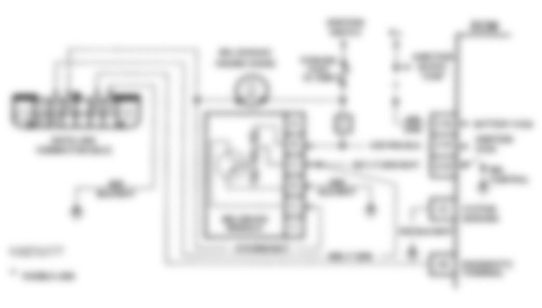
Fig. 11: GMC Yukon 1993 - Component Locations - A-1, Flowchart, No MIL - M/T
GMC Yukon 1993 - A-2, NO DLC DATA, MIL (SERVICE ENGINE SOON) LIGHT ON AT ALL TIMES OR WILL NOT FLASH DTC 12 (WITH A/T)
MIL should be on when engine is off and ignition is on. Switched battery voltage is supplied to MIL light. The ECM turns light on by providing a ground path through circuit No. 419. With diagnostic terminal grounded, MIL should flash DTC 12, followed by any other DTC stored in memory. A steady light on indicates a short to ground in circuit No. 419, or no engine speed sensor signal.
NOTE: Test numbers refer to numbers on diagnostic chart.
- If there is a problem with ECM that causes scan tester not to read serial data, then the ECM should not flash DTC 12. If DTC 12 does flash, ensure scan tester is functioning properly (on another vehicle). If scan tester is functioning properly, and circuit No. 1061 is okay, the PROM or ECM may be at fault for no DLC data symptom.
- If light goes off when ECM connector is disconnected, then circuit No. 419 is not shorted to ground.
- This step checks for an open circuit No. 451.
- At this point, MIL is working properly. The problem is a faulty PROM. If DTC 12 does not flash, the ECM should be replaced using the original PROM. Replace PROM only after trying an ECM. A defective PROM usually is an unlikely cause of the problem.
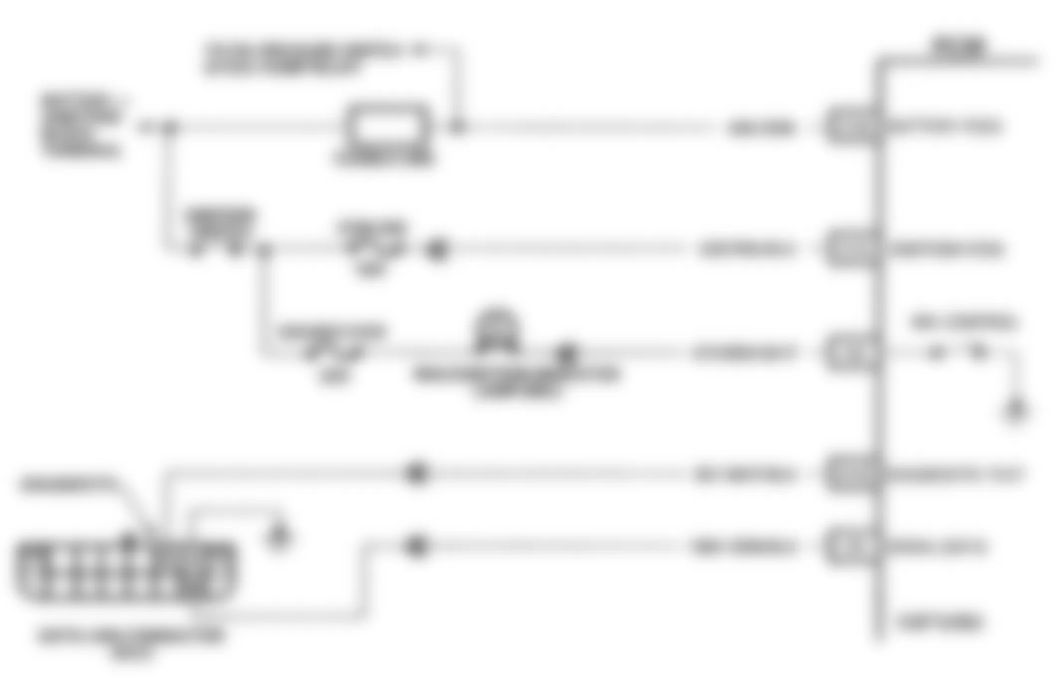
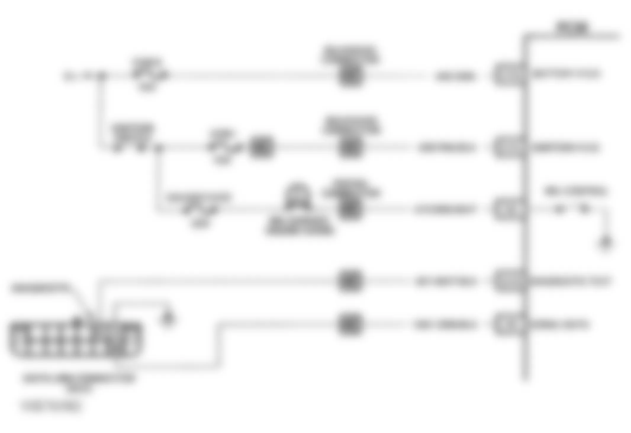
Fig. 14: GMC Yukon 1993 - Component Locations - A-2, Flowchart, No DLC Data, MIL On All Time - A/T
GMC Yukon 1993 - A-2, MIL (SERVICE ENGINE SOON) LT ON AT ALL TIMES OR WILL NOT FLASH DTC 12 (WITH M/T)
The ECM check determines why MIL remains on, or does not flash DTC 12. Normally, ECM will not recognize a fault for at least 10 seconds after engine start-up. If MIL remains on, ECM has lost battery power, ground, or the signal that turns MIL off. When engine is started, ECM grounds terminal A10 to turn off MIL light. ECM alternately grounds and opens terminal A10 to flash DTC.
NOTE: Test numbers refer to numbers on diagnostic chart.
- This tests for a short to battery voltage in wire to MIL driver terminal "C", or a faulty MIL driver. Normal reading is 9-11 volts.
- This tests if problem is related to ECM, or MIL driver. Normally, grounding MIL driver terminal "C" should turn light off. If light goes out when terminal "C" is grounded, problem is related to ECM and its wiring. If light does not go out, problem is related to MIL driver and its wiring.
- Normally, grounding ECM terminal A10 turns light off. If light stays on after grounding terminal A10, there is an open in circuit No. 487 between ECM terminal A10 and MIL driver terminal "C".
- This tests for open circuit No. 451 between ECM and diagnostic terminal "B" in DLC. The light should flash DTC 12 when ECM terminal A6 is grounded.
- This tests for proper voltage supply to ECM. Both readings should be more than 9 volts. Voltage to ECM terminal C14 comes from ignition switch. Terminal C16 has constant battery voltage for long term memory.
- This tests for a bad ground to ECM. Terminal C2 is connected in the ECM.
- This test distinguishes between a faulty ECM and PROM. Normal response is for DTC 51 to flash even though PROM is not installed in the ECM. If DTC 51 is not flashed, ECM is faulty.

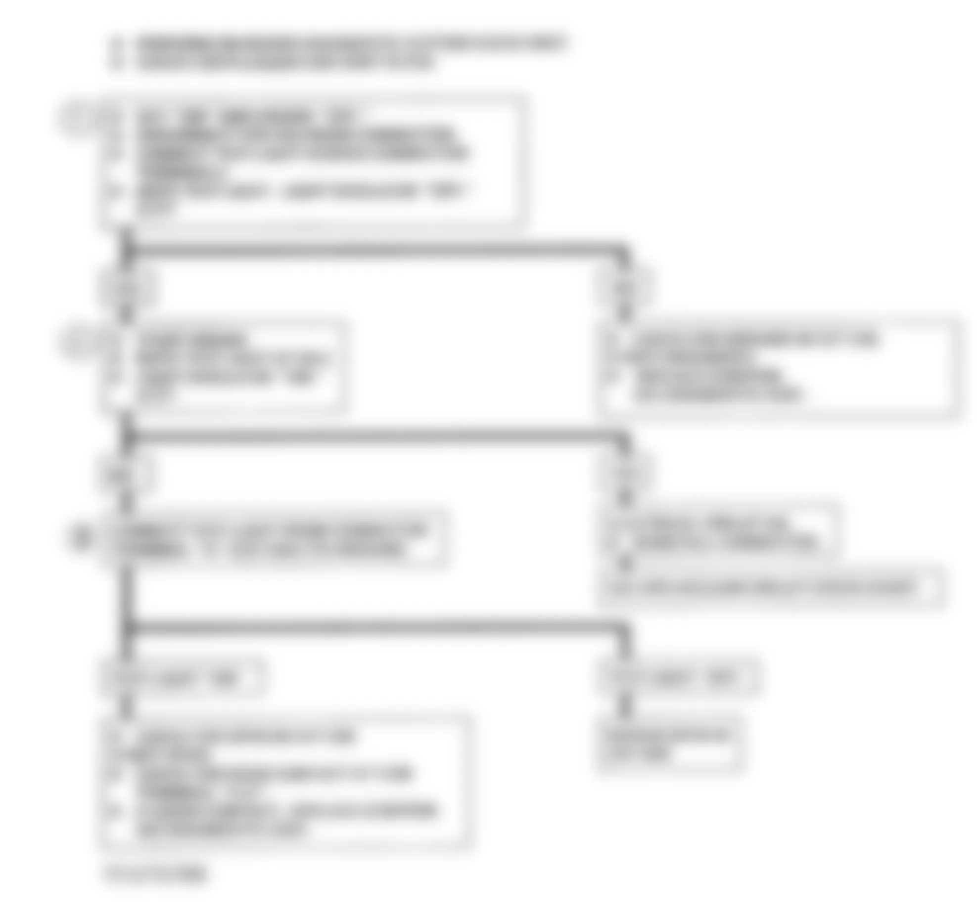
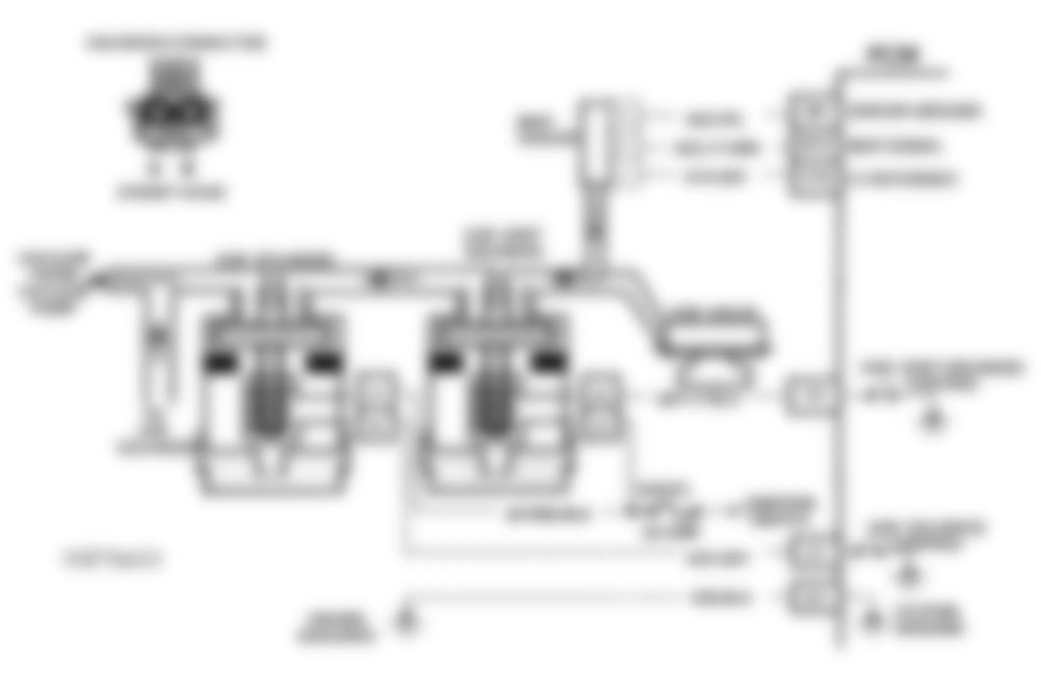
GMC Yukon 1993 - EPR SOLENOID ELECTRICAL CHECK
The Exhaust Pressure Regulation (EPR) solenoid controls vacuum to EPR valve. When energized, EPR solenoid allows vacuum to close EPR valve, increasing exhaust backpressure for proper EGR operation. The solenoid is supplied with 12 volts by ignition switch. ECM completes ground circuit to energize solenoid, and turn EPR on when needed (EGR operation command).
NOTE: Test numbers refer to numbers on diagnostic chart.
- This tests for short to ground, or a faulty ECM signal to EPR solenoid. Test light should normally be off.
- This tests for signal to energize EPR solenoid with engine at idle. If test light is on, electrical circuits to solenoid are okay.
- This tests for voltage or open circuit from terminal "B" of EPR solenoid to ECM terminal C12 ("C" & "K" Series) or F16 ("G" Series) on circuit No. 439 ("C" & "K" Series) or No. 39 ("G" Series).
GMC Yukon 1993 - Diagnostic Aids
Some manual transmission equipped vehicles do not energize the EPR solenoid under normal idle conditions. Use of scan tester should energize solenoid. Prior to replacing ECM, check resistance of EPR solenoid. If resistance is less than 20 ohms, also replace solenoid.
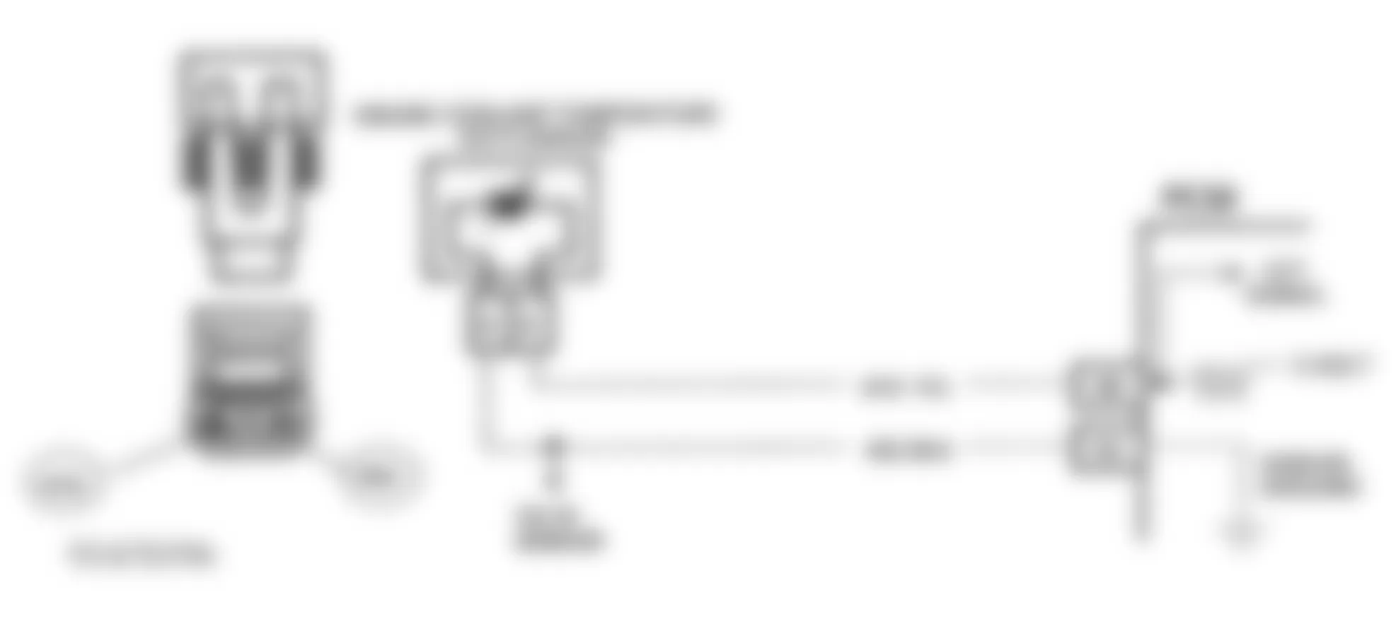
Fig. 17: GMC Yukon 1993 - Component Locations - Schematic, EPR Solenoid Elec. ("C" & "K" Series)

Fig. 18: GMC Yukon 1993 - Component Locations - Schematic, EPR Solenoid Elec. ("G" Series)

Fig. 19: GMC Yukon 1993 - Component Locations - Flowchart, EPR Solenoid Elec.
GMC Yukon 1993 - EPR VACUUM CIRCUIT CHECK
The Exhaust Pressure Regulation (EPR) solenoid controls vacuum to EPR valve. When energized, EPR solenoid allows vacuum to close EPR valve, increasing exhaust backpressure for proper EGR operation.
EPR valve is a combination vacuum actuator and exhaust restrictor plate. When vacuum is applied to actuator, restrictor plate closes to increase exhaust system backpressure to allow EGR valve to function more efficiently.
NOTE: Test numbers refer to numbers on diagnostic chart.
- This tests for normal EPR vacuum at idle. Since electrical circuit was already proven okay in EPR SOLENOID ELECTRICAL CHECK chart, absence of vacuum is due to no vacuum source (vacuum pump), or a restriction or leak in vacuum hose to valve, including a leak in solenoid.
- EPR solenoid is de-energized, no vacuum should be present.
- This tests for normal operation of EPR valve. When vacuum is applied to vacuum valve, valve actuator should move and hold.
Fig. 20: GMC Yukon 1993 - Component Locations - Schematic, EPR Vacuum Circuit ("C" & "K" Series)
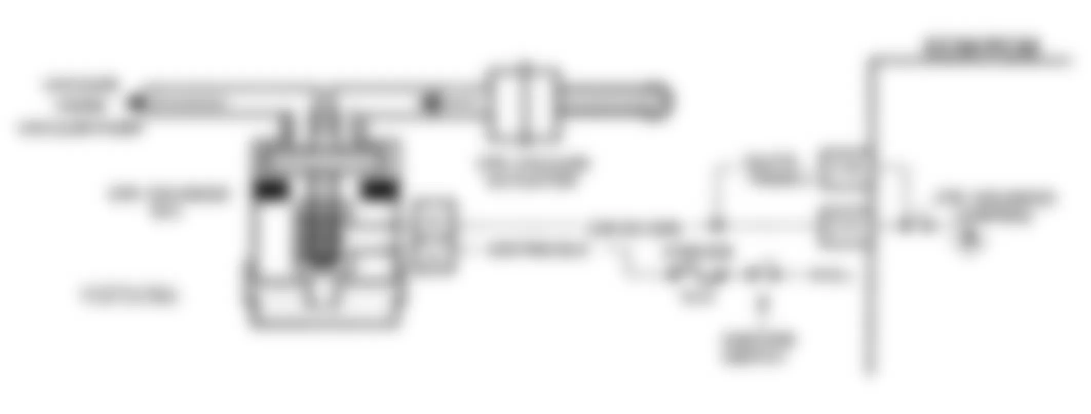
Fig. 21: GMC Yukon 1993 - Component Locations - Schematic, EPR Vacuum Circuit ("G" Series)
Fig. 22: GMC Yukon 1993 - Component Locations - Flowchart, EPR Vacuum Circuit
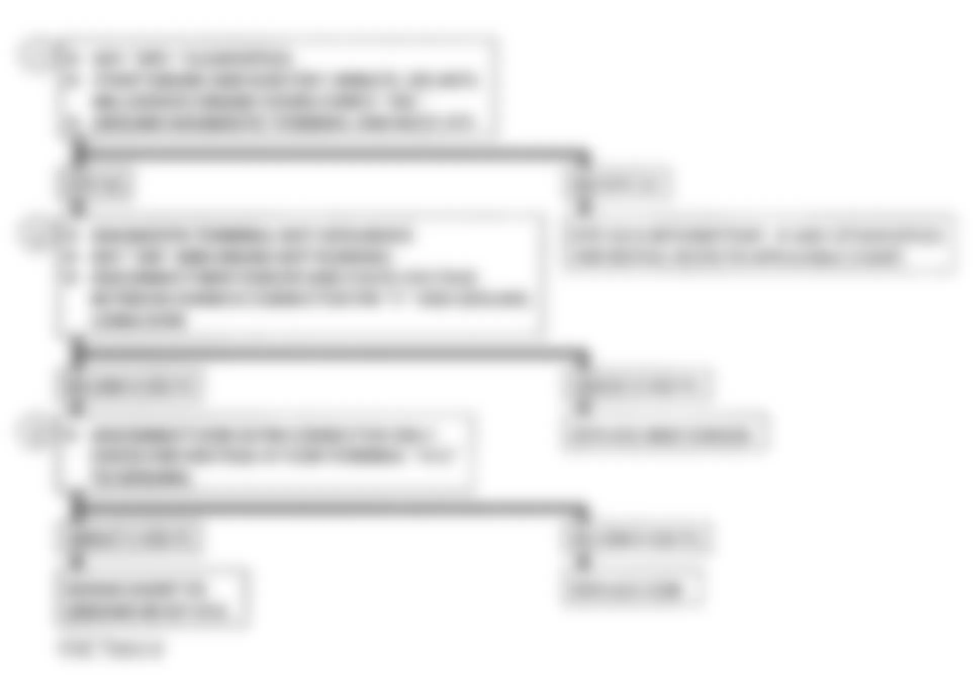
GMC Yukon 1993 - DIAGNOSTIC TROUBLE CODE CHARTS DTC 12, NO REFERENCE PULSE (WITH AUTOMATIC TRANSMISSION)
DTC 12 indicates ECM is on, and sees no reference pulse from engine speed sensor. DTC display is normal with ignition on and engine not running. DTC 12 is not stored and will only flash when fault is present. DTC 12 with engine running could indicate an open or ground in engine speed sensor reference circuit.
The engine speed sensor is a camshaft-driven pick-up, mounted at center rear of engine. Sensor is supplied with a 5-volt reference voltage by ECM, and allows ECM to measure engine RPM by the number of times voltage is pulsed. The engine speed sensor pulses reference voltage 4 times per revolution.
NOTE: Test numbers refer to numbers on diagnostic chart.
- This tests for proper ECM voltage to the engine speed sensor. If circuit to ECM is complete, normal voltage will be about 5 volts with harness disconnected from sensor.
- This tests for good sensor ground circuit No. 642 from sensor to ECM. Since result of previous step indicates an open exists, this test will determine if open circuit is in wire or at ECM.
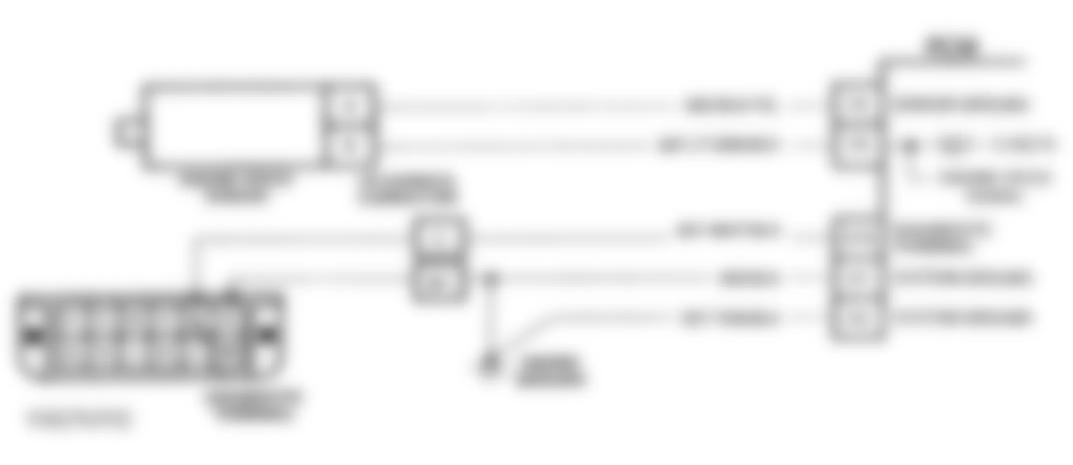
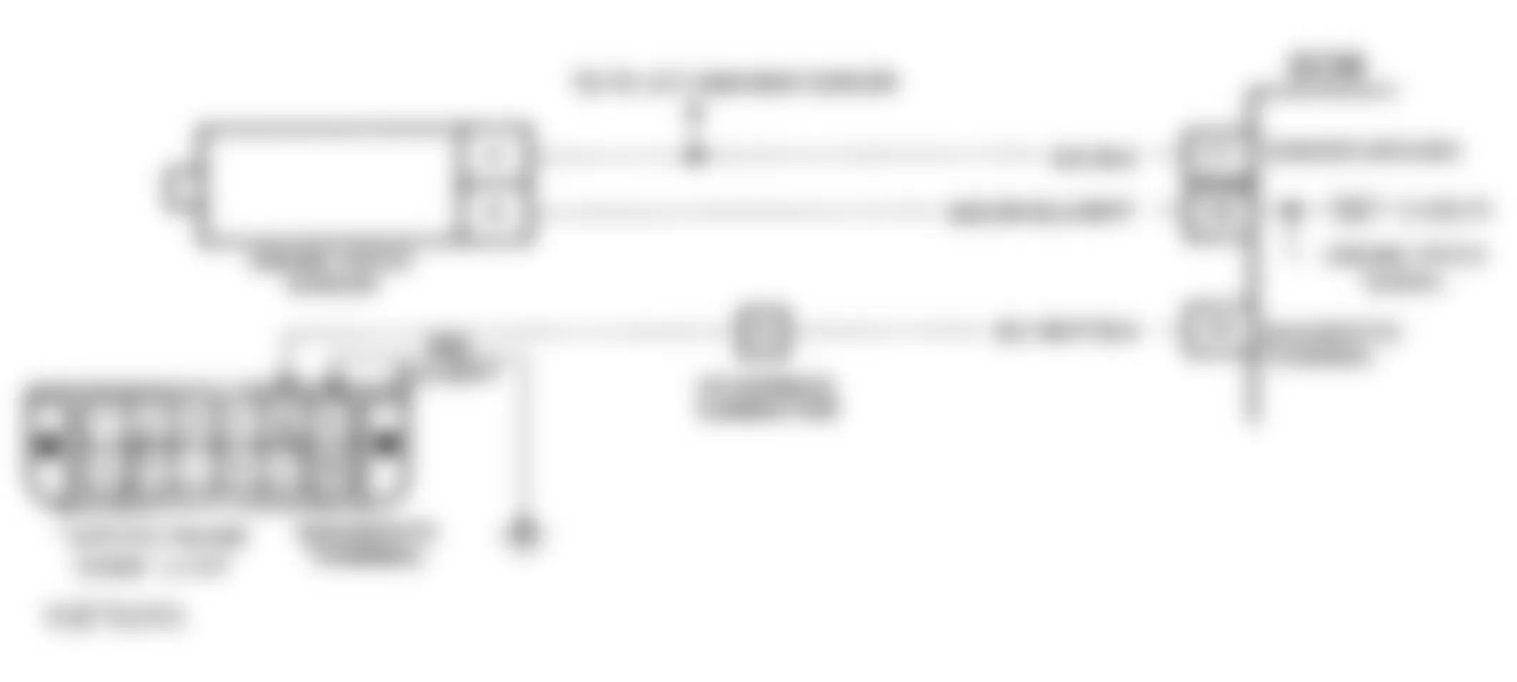
Fig. 25: GMC Yukon 1993 - Component Locations - DTC 12, Flowchart, No Reference Pulse - A/T
GMC Yukon 1993 - DTC 12, NO REFERENCE PULSE (WITH MANUAL TRANSMISSION)
DTC 12 indicates ECM is on, and sees no reference pulse from engine speed sensor. DTC display is normal with ignition on and engine not running. DTC 12 is not stored and will only flash when fault is present. DTC 12 with engine running could indicate an open or ground in engine speed sensor reference circuit.
The engine speed sensor is a camshaft-driven pick-up, mounted at center rear of engine. Sensor is supplied with a 5-volt reference voltage by ECM, and allows ECM to measure engine RPM by the number of times voltage is pulsed. The engine speed sensor pulses reference voltage 4 times per revolution.
NOTE: Test numbers refer to numbers on diagnostic chart.
- This tests for a good 5-volt reference. Normally, ECM should be at about 5 volts for fully charged batteries. Ensure Digital Volt-Ohmmeter (DVOM) is connected to a known good ground.
- This tests for proper ECM voltage to the engine speed sensor. If circuit to ECM is complete, normal voltage will be about 5 volts with harness disconnected from sensor.
- This tests for good sensor ground circuit No. 452 from sensor to ECM. Since result of previous step indicates an open exists, this test will determine if open circuit is in wire or at ECM.
Fig. 26: GMC Yukon 1993 - Component Locations - DTC 12, Schematic, No Reference Pulse (M/T)

Fig. 27: GMC Yukon 1993 - Component Locations - DTC 12, Flowchart, No Reference Pulse (M/T)

GMC Yukon 1993 - DTC 14, ECT SENSOR - HIGH TEMPERATURE INDICATED (WITH A/T)
The Engine Coolant Temperature (ECT) sensor uses a thermistor to control signal voltage from ECM. The ECM applies and monitors voltage over circuit No. 410 to sensor. When engine is cold, sensor resistance is high, the ECM will sense a high signal voltage. As engine warms, sensor resistance becomes less and voltage drops. At normal engine operating temperature, voltage will be 1.5-2.0 volts. When DTC 14 sets, early application of torque converter clutch will occur.
NOTE: Test numbers refer to numbers on diagnostic chart.
- DTC 14 will set if signal voltage indicates a coolant temperature greater than 293?F (145?C) for 0.5 second.
- This test determines if circuit No. 410 is shorted to ground, causing conditions for DTC 14 to set.
GMC Yukon 1993 - Diagnostic Aids
Check circuit No. 410 wiring harness routing for a potential short circuit to ground. Scan tester displays engine temperature in degrees Celsius. After starting engine, temperature should rise to about 90?C and stabilize when thermostat opens. Test coolant sensor at various temperature levels. See TEMPERATURE VS. RESISTANCE VALUES chart. An out-of-calibration sensor can cause poor driveability.
GMC Yukon 1993 - DTC 14, ECT SENSOR HIGH TEMPERATURE INDICATED (WITH M/T)
The Engine Coolant Temperature (ECT) sensor uses a thermistor to control signal voltage from ECM. The ECM applies and monitors voltage over circuit No. 410 to sensor. When engine is cold, sensor resistance is high. The ECM will sense a high signal voltage. As engine warms, sensor resistance becomes less and voltage drops. At normal engine operating temperature, voltage will be 1.5-2.0 volts.
NOTE: Test numbers refer to numbers on diagnostic chart.
- DTC 14 will set if signal voltage indicates a coolant temperature greater than 275?F (135?C) for 3 minutes.
- This test simulates conditions for DTC 15 to set. If ECM recognizes the open circuit (high voltage) and displays a low temperature, the ECM and wiring are okay.
GMC Yukon 1993 - Diagnostic Aids
Check circuit No. 410 wiring harness routing for a potential short circuit to circuit No. 452 or ground. Scan tester displays engine temperature in degrees Celsius. After starting engine, temperature should rise to about 90?C and stabilize when thermostat opens. Test coolant sensor at various temperature levels. See TEMPERATURE VS. RESISTANCE VALUES chart. An out-of-calibration sensor can cause poor driveability.

GMC Yukon 1993 - DTC 15, ECT SENSOR LOW TEMPERATURE INDICATED (WITH A/ T)
The Engine Coolant Temperature (ECT) sensor uses a thermistor which controls signal voltage from ECM. The ECM applies and monitors voltage over circuit No. 410 to sensor. When engine is cold, sensor resistance is high, the ECM will sense a high signal voltage. As engine warms, sensor resistance reduces and voltage drops. At normal engine operating temperature, voltage should be 1.5-2.0 volts. When DTC 15 sets, early application of torque converter clutch will occur.
NOTE: Test numbers refer to numbers on diagnostic chart.
- DTC 15 will set if signal voltage indicates a coolant temperature less than -27?F (-33?C) for 0.5 second.
- This test simulates DTC 14. If ECM recognizes low signal voltage (high temperature), and scan tester reads 145?C or greater, ECM and wiring are okay.
- This test determines if circuit No. 410 is open. Voltage at sensor connector should be 5 volts when measured with Digital Volt-Ohmmeter (DVOM).
GMC Yukon 1993 - Diagnostic Aids
Scan tester displays engine temperature in degrees Celsius. After starting engine, temperature should rise to about 90?C and stabilize when thermostat opens. A faulty connection or an open in circuits No. 410 or 452 can result in DTC 15. Test coolant sensor at various temperature levels. See TEMPERATURE VS. RESISTANCE VALUES chart. An out-of-calibration sensor can cause poor driveability.

GMC Yukon 1993 - DTC 15, ECT SENSOR LOW TEMPERATURE INDICATED (WITH M/T)
The Engine Coolant Temperature (ECT) sensor uses a thermistor which controls signal voltage from ECM. The ECM applies and monitors voltage over circuit No. 410 to sensor. When engine is cold, sensor resistance is high, the ECM will sense a high signal voltage. As engine warms, sensor resistance reduces and voltage drops. At normal engine operating temperature, voltage should be 1.5-2.0 volts.
NOTE: Test numbers refer to numbers on diagnostic chart.
- This checks if DTC was set as a result of a hard failure or intermittent condition. DTC 15 will set if engine has run for more than 5 minutes and coolant temperature is less than -22?F (-30?C).
- This test simulates DTC 14. If ECM recognizes low signal voltage (high temperature), and scan tester reads 130?C or greater, ECM and wiring are okay.
- This test determines if circuit No. 410 is open. Voltage at sensor connector should be 5 volts when measured with Digital Volt-Ohmmeter (DVOM).
GMC Yukon 1993 - Diagnostic Aids
Scan tester displays engine temperature in degrees Celsius. After starting engine, temperature should rise to about 90?C and stabilize when thermostat opens. If DTC 12 or 21 is also set, check circuit No. 452 for faulty wiring or connections. Check terminals at sensor connector. Test coolant sensor at various temperature levels. See TEMPERATURE VS. RESISTANCE VALUES chart. An out-of-calibration sensor can cause poor driveability.

GMC Yukon 1993 - DTC 16, TRANS. OUTPUT SPEED SIGNAL VOLTAGE LOW (A/T ONLY)
This DTC concerns itself with the loss of the 2002 pulses per mile signal to ECM terminal F13. This may be caused by a loss of power to the VSS buffer or an open or grounded circuit. Listed below are the conditions, which must be met for 3 seconds, under which the DTC will set:
- Vehicle speed less than 2 MPH.
- 1000-4000 RPM.
- Throttle angle less than 2 degrees.
- Engine coolant temperature greater than 140?F (60?C).
- Circuit No. 1716 open or grounded.
NOTE: Test numbers refer to numbers on diagnostic chart.
- This tests for battery voltage at VSS buffer.
- Tests for proper ground path for vehicle speed sensor signal buffer.
- This tests for vehicle speed sensor signal buffer CM. Use Digital Volt-Ohmmeter (DVOM) on 20-volt DC scale.
- This tests for a signal from VSS buffer to ECM.
GMC Yukon 1993 - Diagnostic Aids
Check connections at VSS buffer and ECM. Check for codes DTC 24 or DTC 72.
GMC Yukon 1993 - DTC 21, THROTTLE POSITION SENSOR SIGNAL VOLTAGE HIGH (W/ A/T)
The Throttle Position (TP) sensor provides a voltage signal that changes relative to throttle opening. Signal voltage will vary from about 0.5 volt at idle to over 5 volts at Wide Open throttle (WOT). Throttle position signal is one of the most important inputs used by the ECM for transmission control and for most of the ECM control outputs. With throttle closed, TP signal should read less than 1.25 volts. When DTC 21 sets, the following occurs:
- Torque converter clutch will not be applied.
- Pressure control solenoid current will be low, resulting in high line pressure.
- Fixed or harsh shift points, and no 4th gear when hot.
NOTE: Test numbers refer to numbers on diagnostic chart.
- DTC 21 sets if TP signal voltage is greater than 4.9 volts at WOT for 4 seconds.
- With TP sensor disconnected, TP voltage should go low if the ECM and wiring are okay.
- Probing circuit No. 452 with a test light checks the 5-volt return circuit.
GMC Yukon 1993 - Diagnostic Aids
Scan tester displays TP signal in volts, and should display 0.5-1.25 volts with throttle closed and ignition on or engine at idle. Voltage should increase at a steady rate as throttle is moved toward WOT. Monitor TP signal while applying accelerator pedal with engine off and ignition on. Display should vary from less than 1.25 volts with throttle closed, to more than 4.0 volts with throttle at WOT.
Fig. 40: GMC Yukon 1993 - Component Locations - DTC 21, Schematic, TPS Signal Voltage High (A/T)

GMC Yukon 1993 - DTC 21, THROTTLE POSITION SENSOR SIGNAL VOLTAGE HIGH (W/ M/T)
The Throttle Position (TP) sensor provides a voltage signal that changes relative to throttle opening. Signal voltage will vary from about 0.5 volt at idle to over 5 volts at Wide Open throttle (WOT). Full TP sensor signal voltage will be reached at about 50 percent of throttle travel. If diagnostic procedure points to an intermittent, check pin connections at TP sensor connector. When DTC 21 sets, exhaust pressure regulator solenoid is shut off. DTC sets when ECM senses a high voltage at ECM terminal A2, for at least 2 minutes, and engine speed is less than 1120 RPM.
NOTE: Test numbers refer to numbers on diagnostic chart.
- This test confirms DTC 21 fault is present. Ensure Digital Volt-Ohmmeter (DVOM) is connected to a known good ground.
- This tests for 5-volt reference signal at TP sensor harness connector and separates an electrical circuit problem from a faulty TP sensor. If circuit is okay, normal voltage reading will be 5 volts.
- This checks if low reference voltage is due to an open wire or ECM.
Fig. 43: GMC Yukon 1993 - Component Locations - DTC 21, Schematic, TPS Signal Voltage High (M/T)
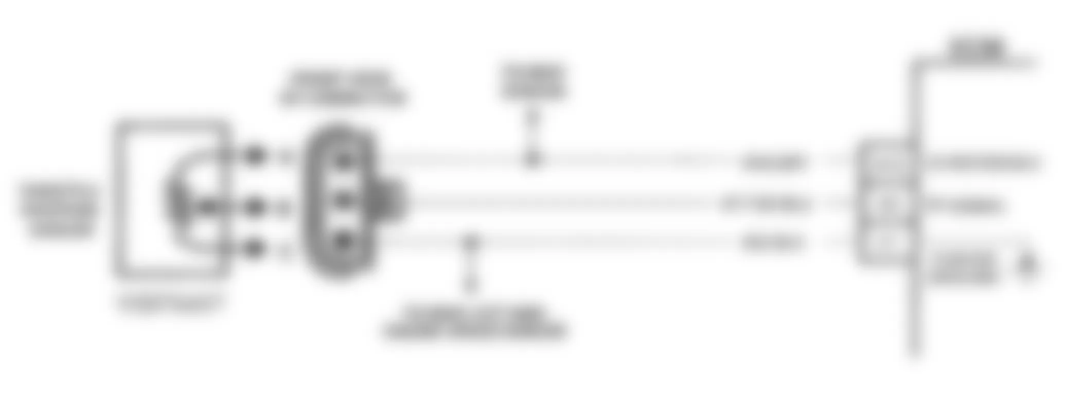
Fig. 44: GMC Yukon 1993 - Component Locations - DTC 21, Flowchart, TPS Signal Voltage High (M/T)
GMC Yukon 1993 - DTC 22, THROTTLE POSITION SENSOR SIGNAL VOLTAGE LOW (W/ A/T)
The Throttle Position (TP) sensor provides a voltage signal that changes relative to throttle opening. Signal voltage will vary from about 0.5 volt at idle to greater than 5 volts at Wide Open throttle (WOT). Throttle position signal is one of the most important inputs used by the ECM for transmission control and for most of the ECM control outputs. With throttle closed, TP signal should read less than 1.25 volts. When DTC 22 sets, the following occurs:
- Torque converter clutch will not be applied.
- Pressure control solenoid current will be low, resulting in high line pressure and harsh shifts.
NOTE: Test numbers refer to numbers on diagnostic chart.
- DTC 22 will set if TP sensor signal voltage is less than 0.06 volt for 4 seconds.
- This test simulates DTC 21 (high voltage). If ECM recognizes high signal voltage, ECM and wiring are okay.
- This test simulates a high signal voltage to check for an open circuit No. 417.
Fig. 45: GMC Yukon 1993 - Component Locations - DTC 22, Schematic, TPS Signal Voltage Low (A/T)

Fig. 46: GMC Yukon 1993 - Component Locations - DTC 22, Flowchart, TPS Signal Voltage Low (A/T)
GMC Yukon 1993 - DTC 22, THROTTLE POSITION SENSOR SIGNAL VOLTAGE LOW (W/ M/T)
The Throttle Position (TP) sensor provides a voltage signal that changes relative to throttle opening. Signal voltage will vary from about 0.5 volt at idle to over 5 volts at Wide Open throttle (WOT). DTC sets when ECM senses a low voltage at ECM terminal A2, for at least 2 minutes, and engine speed is more than 1250 RPM.
NOTE: Test numbers refer to numbers on diagnostic chart.
- This test confirms DTC 22 fault is present.
- This test simulates DTC 21 (high voltage). If ECM recognizes high signal voltage, ECM and wiring are okay. If signal voltage is still low, DTC 23 will set because test was performed at less than 1250 RPM.
Fig. 47: GMC Yukon 1993 - Component Locations - DTC 22, Schematic, TPS Signal Voltage Low (M/T)

Fig. 48: GMC Yukon 1993 - Component Locations - DTC 22, Flowchart, TPS Signal Voltage Low (M/T)
GMC Yukon 1993 - DTC 23, THROTTLE POSITION SENSOR MISADJUSTED
The Throttle Position (TP) sensor provides a voltage signal that changes relative to throttle opening. Signal voltage will vary from about 0.5 volt at idle to over 5 volts at Wide Open throttle (WOT). DTC sets when ECM senses that voltage is not between 0.25-1.35 volts at ECM terminal A15, for at least 30 seconds, and engine speed is 550-650 RPM.
NOTE: Test numbers refer to numbers on diagnostic chart.
- This confirms DTC 23 fault is present.
- This test determines if sensor signal circuit is shorted to ground.
- Adjust throttle position sensor. See THROTTLE POSITION SENSOR in REMOVE/INSTALL/OVERHAUL article in this section.
GMC Yukon 1993 - Diagnostic Aids
Disregard DTC 23 if MIL goes out when throttle is returned to idle.


Fig. 51: GMC Yukon 1993 - Component Locations - DTC 23, Flowchart, TPS Misadjusted
GMC Yukon 1993 - DTC 24, VEHICLE SPEED SIGNAL LOW ("C" & "K" SERIES, M/T ONLY)
The ECM applies and monitors 12 volts on circuit No. 437. Circuit No. 437 connects to Vehicle Speed Sensor (VSS) buffer, which alternately grounds circuit No. 437 when receiving voltage pulses from VSS (drive wheels are turning). The pulsing action occurs approximately 2000 times per mile and the ECM calculates vehicle speed based on the time between pulses. Scan tester reading should closely match speedometer reading with drive wheels turning.
NOTE: Test numbers refer to numbers on diagnostic chart.
- DTC 24 will set after the following conditions are met for at least 40 seconds: circuit No. 437 voltage is constant, engine speed is more than 2000 RPM, and vehicle speed signal at ECM terminal A9 is less than 5 MPH.
- This test determines if VSS buffer is receiving alternating current signal from vehicle speed sensor. Use Digital Volt-Ohmmeter (DVOM) on 20-volt AC scale.
- This test monitors voltage on circuit No. 437. With wheels turning, the pulsating action causes a varying voltage. Voltage variation will be greater at low wheel speeds and an average of 4-6 volts at about 20 MPH.
GMC Yukon 1993 - Diagnostic Aids
With drive wheels turning, scan tester and speedometer reading should closely match.
GMC Yukon 1993 - DTC 24, VEHICLE SPEED SIGNAL LOW (WITH 4L60-E A/T)
The speed sensor circuit consists of a magnetic-induction sensor, Vehicle Speed Sensor (VSS) buffer, and wiring. Gear teeth on output shaft induce an alternating current in sensor. This signal is then transmitted to buffer. The buffer compensates for various axle ratios and converts signal into a square wave signal for use by the speedometer, cruise control ABS, and ECM.
The buffer sends 2 different signals to the ECM. circuit No. 437 relays transmission output speed, which is used to control shift points, line pressure torque converter clutch and DTC 24 and 72. Circuit No. 1716 relays vehicle speed which is used to control engine operating conditions and DTC 16. When DTC 24 sets, only 2nd gear at maximum line pressure will occur. DTC 24 sets when the following conditions are met for 6.4 seconds:
- Transmission is not in Park or Neutral.
- Circuit No. 437 voltage is constant.
- Engine speed is more than 3000 RPM.
- Output speed less than 250 RPM.
- Manifold absolute pressure 14.5-36.9 psi (100-255 kPa).
- Throttle position 10-100 percent.
NOTE: Test numbers refer to numbers on diagnostic chart.
- This test monitors voltage on circuit No. 437. With wheels turning, the pulsating action causes a varying voltage. Voltage variation will be greater at low wheel speeds and an average of 4-6 volts at about 20 MPH.
- Less than one volt at ECM connector indicates circuit No. 437 is shorted to ground. Disconnect circuit No. 437 at VSS buffer. If voltage now reads more than 10 volts, the VSS buffer is faulty. If voltage remains less than 10 volts, then circuit No. 437 is grounded. If circuit No. 437 is not grounded, check for a faulty ECM connector or ECM.
- A steady 8-12 volt reading at the ECM connector indicates that circuit No. 437 is open or VSS buffer is faulty.
GMC Yukon 1993 - Diagnostic Aids
Check all connections at transmission pass-through connector.
GMC Yukon 1993 - DTC 24, VEHICLE SPEED SIGNAL LOW (WITH 4L80-E A/T)
The PCM/TCM applies and monitors 12 volts on circuit No. 437. Circuit No. 437 connects to Vehicle Speed Sensor (VSS) buffer, which alternately grounds circuit No. 437 when receiving voltage pulses from VSS (drive wheels are turning). The pulsing action occurs approximately 2000 times per mile and the ECM calculates vehicle speed based on the time between pulses. Scan tester reading should closely match speedometer reading with drive wheels turning. DTC 24 sets when the following conditions are met for 5 seconds:
- Transmission is not in Park or Neutral.
- Circuit No. 437 voltage is constant.
- Engine speed is more than 1200 RPM.
- VSS signal indicates less than 2 MPH.
NOTE: Test numbers refer to numbers on diagnostic chart.
- This test monitors voltage on circuit No. 437. With wheels turning, the pulsating action causes a varying voltage. Voltage variation will be greater at low wheel speeds and an average of 4-6 volts at about 20 MPH.
- Less than one volt at PCM/TCM connector indicates circuit No. 437 is shorted to ground. Disconnect circuit No. 437 at VSS buffer. If voltage now reads more than 10 volts, the VSS buffer is faulty. If voltage remains less than 10 volts, then circuit No. 437 is grounded. If circuit No. 437 is not grounded, check for a faulty PCM/TCM connector or faulty PCM/TCM.
- A steady 8-12 volt reading at the PCM/TCM connector indicates circuit No. 437 is open or VSS buffer is faulty.
- This is normal voltage, which indicates a possible intermittent condition.
GMC Yukon 1993 - Diagnostic Aids
Check all connections at transmission pass-through connector.
GMC Yukon 1993 - DTC 31, MAP SENSOR SIGNAL VOLTAGE LOW (W/ A/T)
The Manifold Absolute Pressure (MAP) sensor monitors vacuum in Exhaust Gas Recirculation (EGR) circuit and sends a signal back to ECM. The signal is compared to EGR duty cycle calculated by ECM. If there is a difference in ECM command and vacuum sensed by MAP sensor, ECM makes minor adjustments. When a major difference is sensed, ECM recognizes a fault and sends a full EGR signal.
NOTE: Test numbers refer to numbers on diagnostic chart.
- This confirms DTC 31 fault is present. DTC 31 sets when engine speed is less than 1200 RPM and MAP reading is less than 1.83 psi (12.6 kPa) for at least one second.
- Attaching a jumper wire between harness terminals "B" to "C", will determine if sensor is at fault, or if there is a problem with ECM or wiring.
- Tech 1 scan tester may not display 5 volts. The important thing is that ECM recognized the voltage as more than 4 volts, indicating that circuit No. 432 and ECM are okay.
GMC Yukon 1993 - Diagnostic Aids
An intermittent open in circuits No. 432 or 474 will result in DTC 31.

GMC Yukon 1993 - DTC 31, MAP SENSOR SIGNAL VOLTAGE LOW (W/ M/T)
The Manifold Absolute Pressure (MAP) sensor monitors vacuum in Exhaust Gas Recirculation (EGR) circuit and sends a signal back to ECM. The signal is compared to EGR duty cycle calculated by ECM. If there is a difference in ECM command and vacuum sensed by MAP sensor, ECM makes minor adjustments. When a major difference is sensed, ECM recognizes a fault and sends a full EGR signal.
NOTE: Test numbers refer to numbers on diagnostic chart.
- This tests if sensor is at fault for the low voltage signal or if there is an ECM or wiring problem.
- This simulates a high signal voltage to check for an open circuit No. 432. If test light is bright during this test, circuit No. 432 is probably shorted to ground. If scan tester reads more than 4 volts, circuit No. 416 can be checked by measuring voltage at terminal "C".

GMC Yukon 1993 - DTC 32, EGR CIRCUIT LOOP ERROR ("C" & "K" SERIES)
During normal operation, the ECM compares EGR duty cycle signal with Manifold Absolute Pressure (MAP) signal and makes adjustments in duty cycle. If actual EGR control vacuum varies from what ECM has previously determined vacuum should be, and this variance continues for 10 seconds or more, a DTC 32 will be set and ECM will shut down EGR.
NOTE: Test numbers refer to numbers on diagnostic chart.
- This determines if DTC 32 can reset.
- This tests EGR solenoid electrical control circuit. Test light should flicker faintly if ECM harness and connections are okay. A faintly flickering light is a slightly pulsating glow as opposed to a bright steady glow from a continuous ground path.
GMC Yukon 1993 - Diagnostic Aids
A vacuum leak may cause DTC 32. Check all vacuum hoses and components connected to vacuum hoses for leaks. Also check cruise control and A/C system vacuum hoses and components.

GMC Yukon 1993 - DTC 32, EGR CIRCUIT LOOP ERROR ("G" SERIES)
During normal operation, the ECM compares EGR duty cycle signal with Manifold Absolute Pressure (MAP) signal and makes adjustments in duty cycle. If actual EGR control vacuum varies from what ECM has previously determined vacuum should be, and this variance continues for 10 seconds or more, a DTC 32 will be set and ECM will shut down EGR.
NOTE: Test numbers refer to numbers on diagnostic chart.
- This determines if DTC 32 can reset.
- This tests EGR solenoid electrical control circuit. Test light should flicker faintly if ECM harness and connections are okay. A faintly flickering light is a slightly pulsating glow as opposed to a bright steady glow from a continuous ground path.
GMC Yukon 1993 - Diagnostic Aids
A vacuum leak may cause DTC 32. Check all vacuum hoses and components connected to vacuum hoses for leaks. Also check cruise control and A/C system vacuum hoses and components.

Fig. 67: GMC Yukon 1993 - Component Locations - DTC 32 - Diagnostic Flowchart ("G" Series)
GMC Yukon 1993 - DTC 33, MANIFOLD ABSOLUTE PRESSURE SENSOR SIGNAL VOLTAGE HIGH
The Manifold Absolute Pressure (MAP) sensor monitors vacuum in Exhaust Gas Recirculation (EGR) circuit and sends a signal back to ECM. The signal is compared to EGR duty cycle calculated by ECM. If there is a difference in ECM command vacuum sensed by MAP sensor, ECM makes minor adjustments. When a major difference is sensed, ECM recognizes a fault and sends a full EGR signal.
NOTE: Test numbers refer to numbers on diagnostic chart.
- This step determines if solenoids are stuck closed.
- This step determines whether a short to ground exists in solenoid circuit, or if ECM is faulty.
GMC Yukon 1993 - Diagnostic Aids
Check MAP sensor for poor electrical connections. Also check for plugged, disconnected, or leaking MAP sensor vacuum hose.
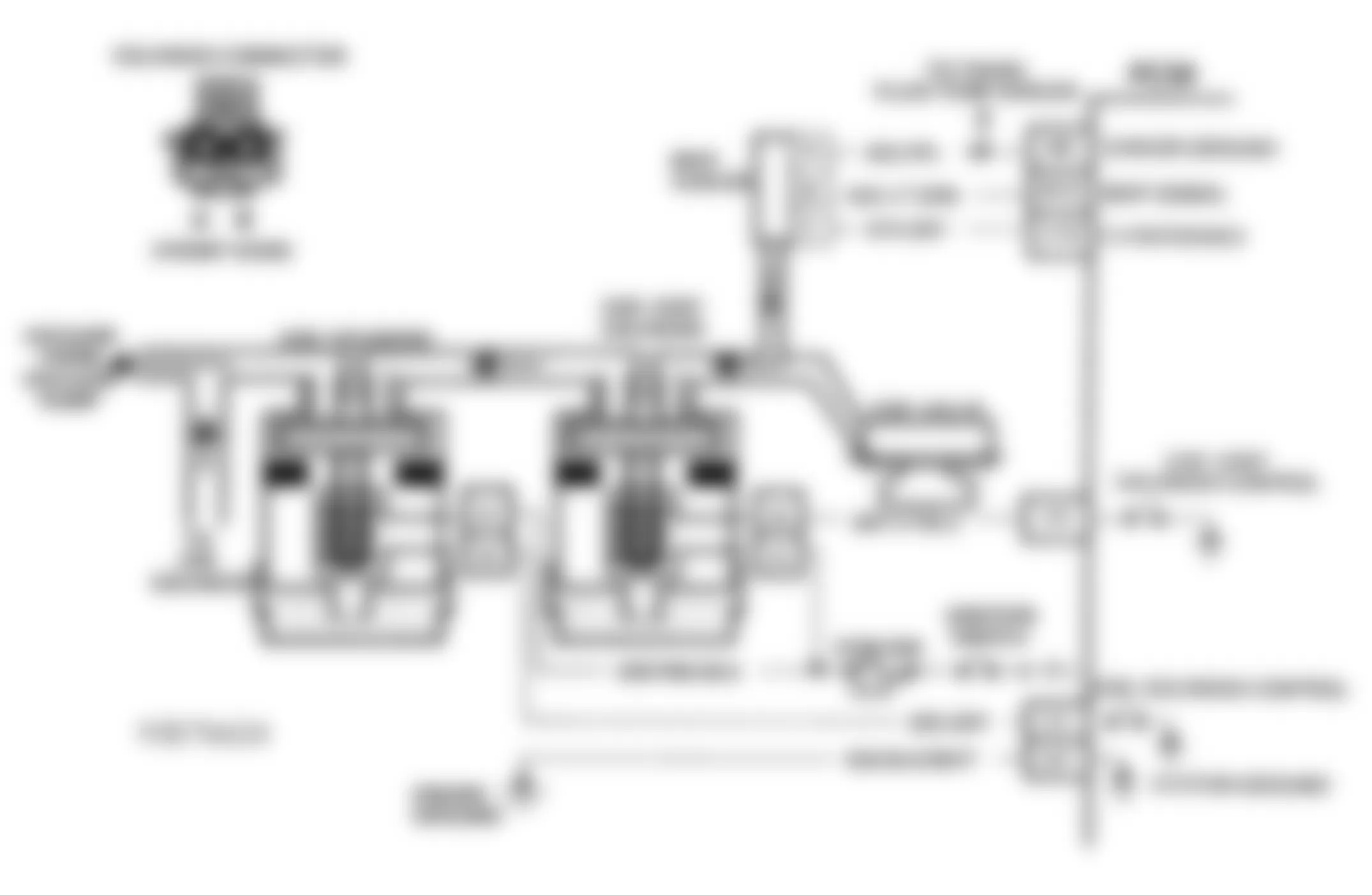


Fig. 71: GMC Yukon 1993 - Component Locations - DTC 33, Flowchart, MAP Sensor Signal Voltage High
GMC Yukon 1993 - DTC 51, PROM PROBLEM
Ensure all pins are fully inserted in socket. If pins are fully inserted, replace PROM and recheck. If problem is not corrected, replace ECM.
GMC Yukon 1993 - DTC 52, ECM FAULT
Ensure ECM connectors are fully inserted. Clear ECM memory. Start engine and check for MIL light. If light and DTC 52 reappear, replace ECM.
GMC Yukon 1993 - DTC 53, VOLTAGE REFERENCE OVERLOAD (W/ A/T)
DTC 53 sets when ignition is on and ECM terminal E16 voltage is greater than 19.5 volts for at least 2 seconds. During the time failure is present, the pressure control solenoid is off, transmission shifts immediately to 3rd gear, and torque converter clutch operation is inhibited. Other DTC codes may set.
NOTE: Test numbers refer to numbers on diagnostic chart.
- Normal battery voltage is 9-15 volts.
- With engine running, check voltage at battery. This tests if high voltage reading is due to alternator, circuit No. 440, or ECM.
- This tests if alternator is faulty under load conditions. If voltage is more than 15 volts, check charging system.
GMC Yukon 1993 - Diagnostic Aids
Charging battery with a battery charger and jump starting engine may set DTC 53. If DTC sets when an accessory is on, check for poor connections or excessive current draw. Check charging system, connections at starter solenoid, and fusible links.


Fig. 74: GMC Yukon 1993 - Component Locations - DTC 53 - Diagnostic Flowchart
GMC Yukon 1993 - DTC 53, VOLTAGE REFERENCE OVERLOAD (WITH MANUAL TRANSMISSION)
The 5-volt reference circuit is overloaded (grounded). It takes 10 seconds before DTC 53 will set.
NOTE: Test numbers refer to numbers on diagnostic chart.
- This confirms DTC 53 is still present.
- This confirms 5-volt reference signal from ECM
- This determines if a short circuit to ground exists in circuit No. 416 or in ECM.
Fig. 75: GMC Yukon 1993 - Component Locations - DTC 53, Schematic, Voltage Reference Overload (M/T)
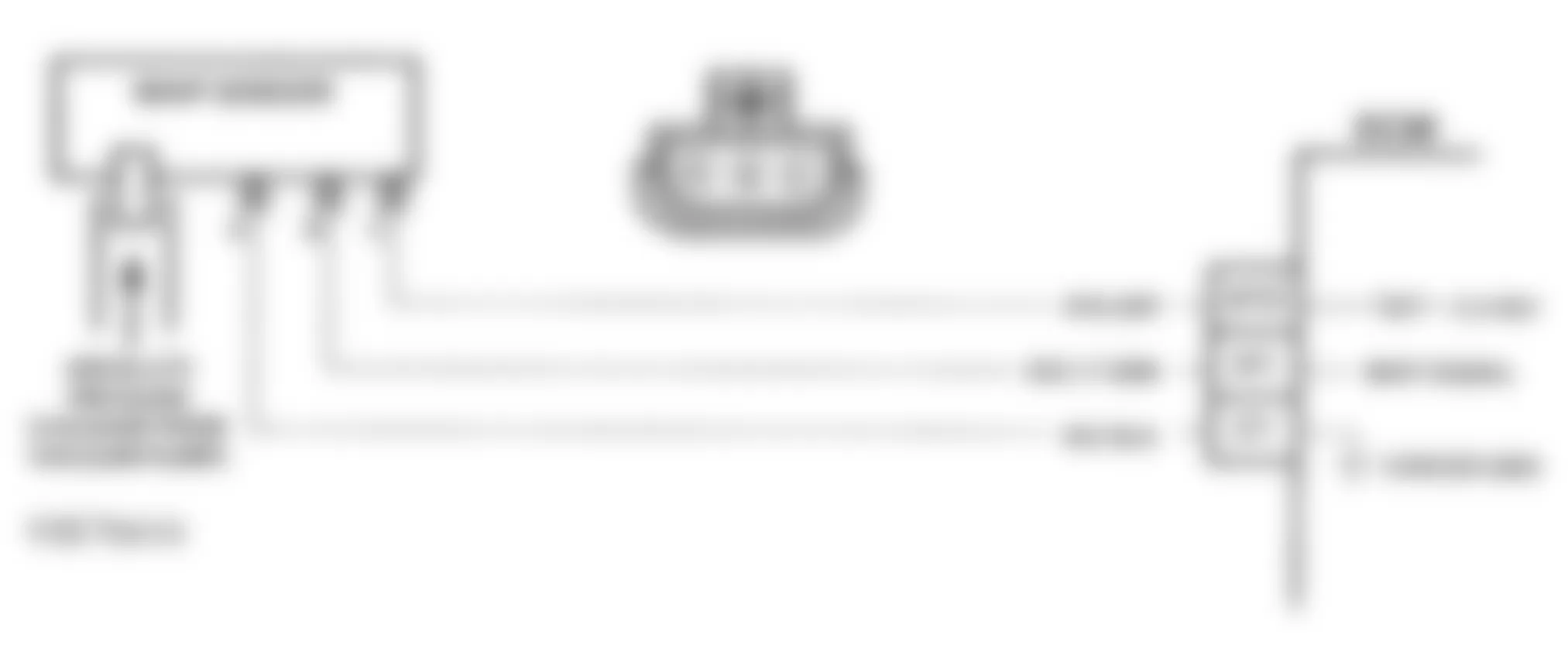
Fig. 76: GMC Yukon 1993 - Component Locations - DTC 53, Flowchart, Voltage Reference Overload (M/T)
GMC Yukon 1993 - DTC 72, VEHICLE SPEED SENSOR SIGNAL LOSS
The speed sensor circuit consists of a magnetic-induction sensor, Vehicle Speed Sensor (VSS) buffer, and wiring. Gear teeth on output shaft induce an alternating current in sensor. This signal is then transmitted to buffer. The buffer compensates for various axle ratios and converts signal into a square wave signal for use by the speedometer, cruise control, ABS and ECM.
The buffer sends 2 different signals to the ECM. Circuit No. 437 relays transmission output speed, which is used to control shift points, line pressure torque converter clutch and DTC 24 and 72. Circuit No. 1716 relays vehicle speed which is used to control engine operating conditions and DTC 16.
On 4WD models, the ECM uses both the transfer case output speed signal and the 4WD low switch to determine transmission output shaft speed. The ECM uses transmission output shaft speed for shift points, line pressure control, torque converter clutch control and DTC 24 and 72.
DTC 72 will set if either of the following conditions is met for 2 seconds:
- Transmission output speed changes more than 1000 RPM (transmission not in Park or Neutral).
- Transmission output speed changes more than 2050 RPM (transmission in Park or Neutral).
NOTE: Test numbers refer to numbers on diagnostic chart.
- This tests vehicle speed sensor signal to ECM. Use Digital Volt-Ohmmeter (DVOM) on 20-volt DC scale.
- This tests vehicle speed sensor signal to vehicle speed sensor buffer.
- This tests vehicle speed sensor signal.
GMC Yukon 1993 - Diagnostic Aids
Check all connections at transmission pass-through connector.
Fig. 77: GMC Yukon 1993 - Component Locations - DTC 72, Schematic, Vehicle Speed Sensor Signal Loss
Fig. 78: GMC Yukon 1993 - Component Locations - DTC 72, Flowchart, Vehicle Speed Sensor Signal Loss