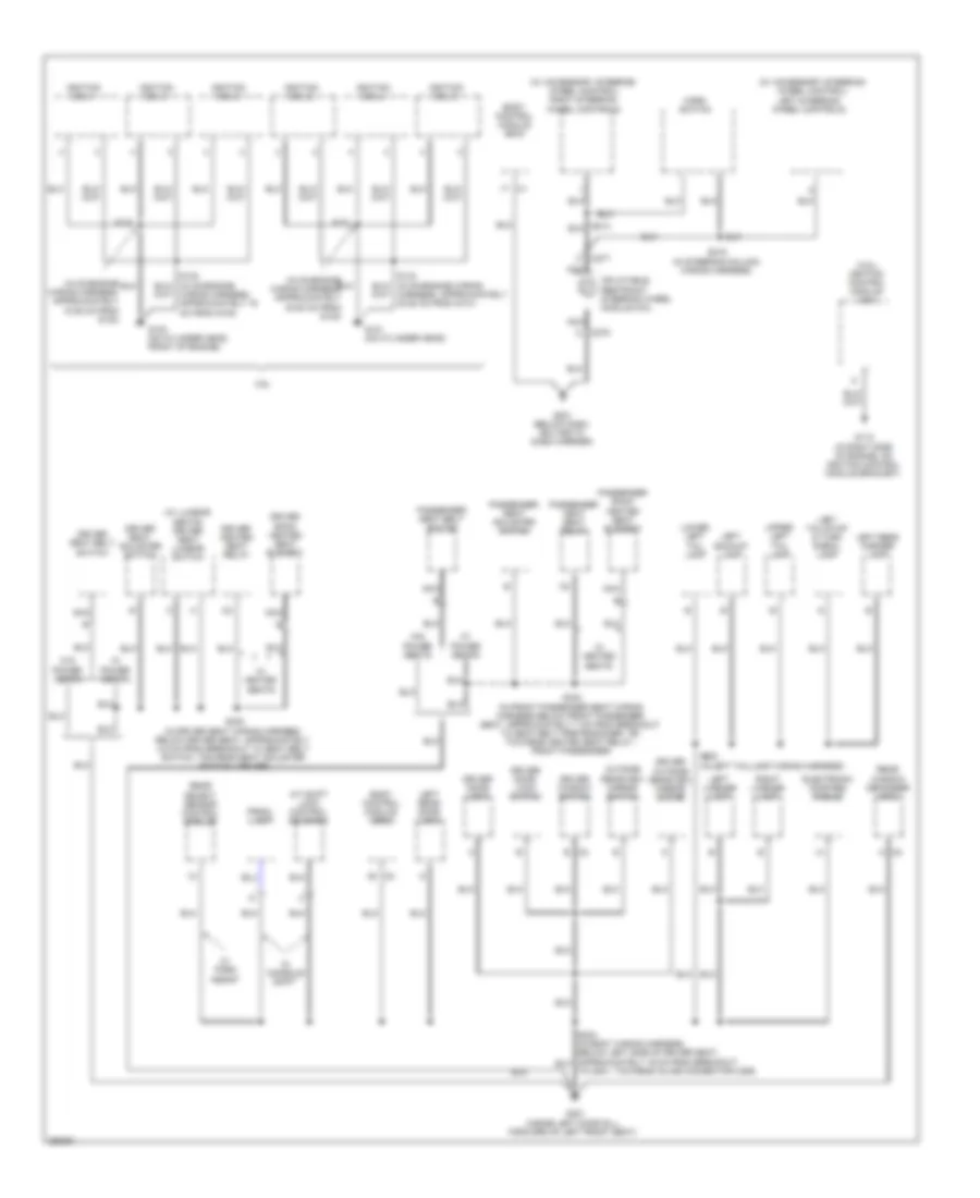
GROUND DISTRIBUTION
Ground Distribution Wiring Diagram (1 of 3) for Buick Allure CXL 2007

List of elements for Ground Distribution Wiring Diagram (1 of 3) for Buick Allure CXL 2007:
- (3.6l) engine control module (ecm)
- (mounted to right strut tower) underhood fuse block
- (sulev) secondary air injection (air) control solenoid valve/ pressure sensor bank 2
- 3.6l
- 3.8l
- A/c clu diode
- A/c clutch diode
- A/c compressor clutch
- Approximately 20 cm from g115)
- Automatic transmission
- B b
- B11
- Battery
- Body control module (bcm)
- C100
- E15
- Electronic brake control module (ebcm)
- Engine oil level switch
- Engine oil pressure (eop) switch
- Except sulev
- Fan 2 relay 46
- Fuel pp relay 41
- G100 (in back of right headlamp on frame)
- G101 (left side of front end upper tie bar, in back of headlamp)
- G102 (3.6l: below right front strut tower) (3.8l: near battery)
- G103 (redundant ground from ecm to even bank cylinder head)
- G111 (3.6l: lower left front of engine, on transmission stud, near starter) (3.8l: lower left side of engine)
- G113 (lower left front of engine, on transmission stud, near starter)
- G115 (mounted to bank 1 cylinder head above exhaust manifold)
- G115 (on transmission stud, to right of starter)
- Hdm beam module 35
- Hood ajar switch
- Horn assembly
- Ign 1 relay 37
- Jumper wiring harness, approximately 5 cm from breakout to left park/turn signal lamp, toward left front fog lamp)
- K14
- Left front fog lamp
- Left front marker lamp
- Left front park/ turn signal lamp
- Left high beam headlamp
- Left low beam headlamp
- Mass air flow (maf)/ intake air temperature (iat) sensor
- Powertrain control module (pcm)
- Right cooling fan
- Right front fog lamp
- Right front marker lamp
- Right front park/ turn signal lamp
- Right high beam headlamp
- Right low beam headlamp
- S101 (in engine wiring harness, in left front of engine compt, approximately 5 cm from breakout to pcm, towards g113)
- S102 (in engine wiring harness. top of engine, approximately 5 cm from breakout to throttle actuator control (tac) module, towards pcm)
- S111
- S112 (in forward lamp harness, approximately 19 cm from left front headlamp assembly)
- S116
- S124 (in forward lamp wiring harness, behind right headlamp, approximately 5 cm from breakout to c142, towards horn assembly)
- S127 (in left headlamp wiring harness)
- Secondary air injection (air) pump (sulev)
- Sulev
- Throttle actuator control (tac) module
- Transmission control module (tcm)
- Transmission internal mode switch (ims)
- Windshield washer fluid level switch
- Windshield washer fluid pump
- Wiper relay 45
- Wiring harness)
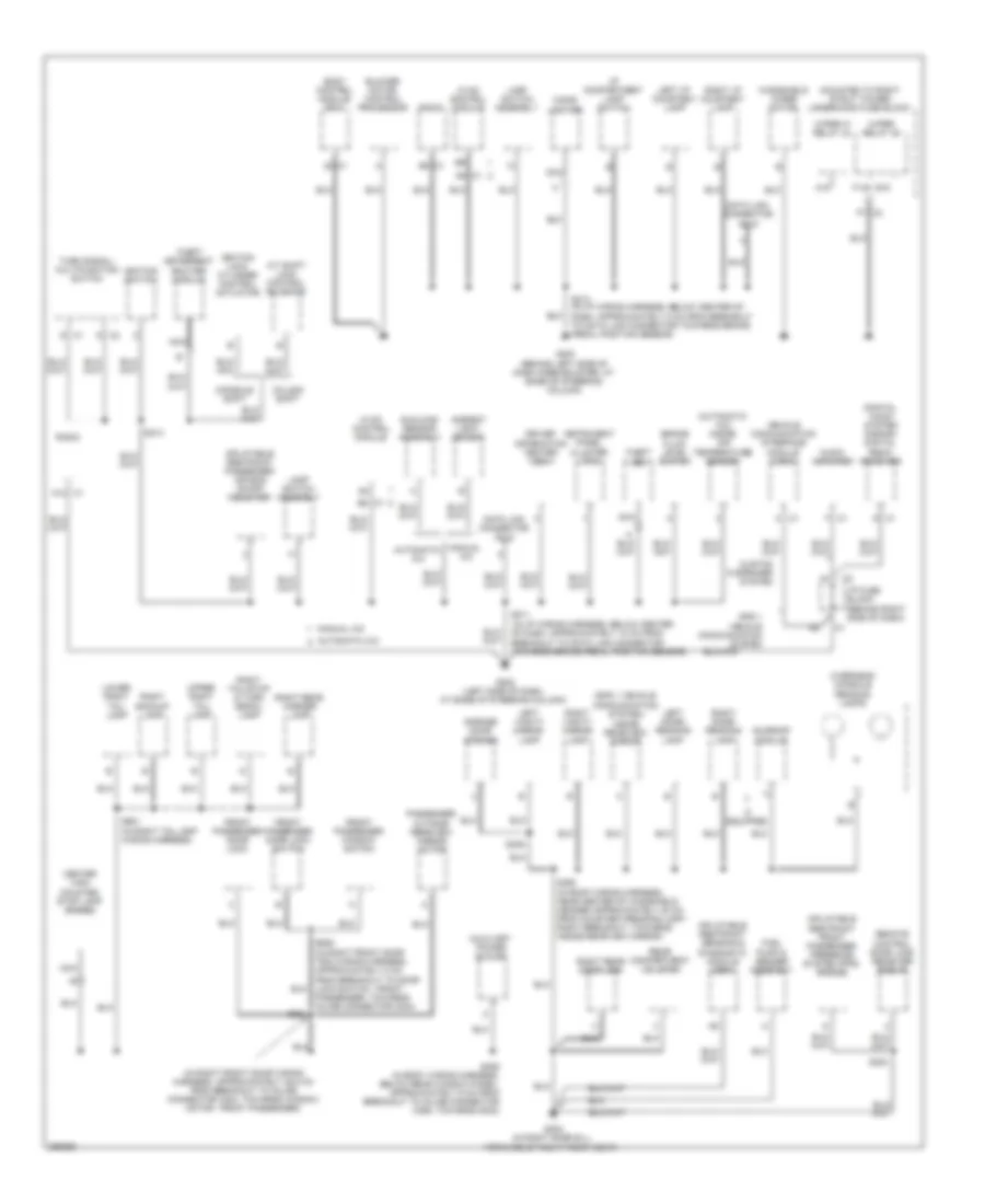
Ground Distribution Wiring Diagram (2 of 3) for Buick Allure CXL 2007
List of elements for Ground Distribution Wiring Diagram (2 of 3) for Buick Allure CXL 2007:
- (3.8l) ignition control module (icm)
- (in on-engine wiring harness, approximately 15.25 cm from g130)
- (in on-engine wiring harness, approximately 30.50 cm from g130)
- (w/ accessory steering wheel control)
- (w/ accessory steering wheel control) right steering wheel controls
- (w/ lumbar seats) driver seat lumbar switch
- 3.6l
- A c2
- A/t shift lock control solenoid
- B c2
- Body control module (bcm)
- C275
- C277
- Driver back heated seat element
- Driver door lock
- Driver door lock switch
- Driver heated seat relay
- Driver outside rearview mirror motor
- Driver seat adjuster switch
- Driver seat belt switch
- Driver window switch
- Electronic compass module
- G112 (in right side of engine, on ignition control module bracket)
- G130 (on cylinder head, front of engine)
- G131 (on cylinder head)
- G201 (below dash, bolted to dash carrier)
- G301 (inside left door sill, forward of left front seat)
- Horn switch
- Ignition coil 1
- Ignition coil 2
- Ignition coil 3
- Ignition coil 4
- Ignition coil 5
- Ignition coil 6
- Inflatable restraint steering wheel module coil
- Left backup lamp
- Left license lamp
- Left rear door lock
- Left rear marker lamp
- Left steering wheel controls
- Left tail/stop & turn signal lamp
- Lower left tail lamp
- Nca
- Outside rearview mirror switch
- Passenger back heated seat element
- Passenger heat seat relay
- Passenger seat adjuster switch
- Passenger seat belt switch
- Prndl lamp
- Rear object sensor control module
- Rear window defogger grid
- Right license lamp
- S130
- S131
- S215 (in steering column wiring harness)
- S330 (in driver seat wiring harness, below driver seat, approximately 4.5 cm from breakout to seat belt switch, towards seat adjuster switch - driver)
- S333 (in front passenger seat wiring harness below front passenger seat, approximately 7 cm from breakout to seat belt pretensioner - rf, towards heated seat relay - front passenger)
- S900 (in left taillamp wiring harness)
- To g301, towards inline connector c355)
- Upper left tail lamp
- W/ console shift
- W/ heated seats
- W/ park assist
- W/ power seats
- W/o power seats
Ground Distribution Wiring Diagram (3 of 3) for Buick Allure CXL 2007
List of elements for Ground Distribution Wiring Diagram (3 of 3) for Buick Allure CXL 2007:
- (automatic a/c) inside air temperature sensor
- (digital audio system s-band) digital radio receiver
- (gps 1 vehicle communication system) inside rearview mirror
- (in i/p wiring harness, below center of dash, approximately 10 cm from breakout to data link connector towards brake pedal position sensor)
- (in i/p wiring harness, below center of dash, approximately 5 cm from breakout to data link connector towards brake pedal position sensor)
- (in right front door wiring harness, approximately 25.5 cm from breakout to inline connector c304, towards window motor - front passenger)
- (mounted to right strut tower) underhood fuse block
- A/t shift lock control solenoid
- A12 c1
- A15
- A6 c1
- Ambient light sensor
- Audio amplifier
- Automatic a/c
- Auxiliary power outlet
- B8 c1
- Blower motor control processor
- Body control module (bcm)
- Brake fluid level switch
- C1 b5
- Center high mounted stop lamp (chmsl)
- Cigar lighter
- Column shift
- Console shift
- Custom 9 speaker system
- D c1
- Data link connector (dlc)
- Driver information center (dic)
- E15
- F c1
- F14
- F7 c2
- Front passenger door lock
- Front passenger door lock switch
- Front passenger window switch
- Fuel pump & sender assembly
- G c2
- G200 (behind left side of dash knee bolster, at base of steering column)
- G202 (left side of dash, at base of steering column)
- G302 (in right door sill, forward of right front seat)
- Garage door opener
- Gps 1 vehicle communication system
- Hvac control module
- I/p compartment lamp switch
- I/p fuse block (behind right side of dash)
- If equipped
- Ignition lock cylinder control actuator
- Ignition switch
- Inflatable restraint front passenger presence system (pps) module
- Inflatable restraint passenger air bag on/off indicator
- Inflatable restraint sensing & diagnostic module (sdm)
- Instrument panel cluster (ipc)
- Lamp switch assembly
- Left dome/ reading lamp
- Left i/p courtesy lamp
- Left vanity mirror lamp
- Lower right tail lamp
- Manual a/c
- Nca
- Overhead console reading lamps
- Passenger outside rearview mirror motor
- Passenger, towards inline connector c304)
- Radio
- Rear compartment lid latch
- Remote control door lock receiver (rcdlr)
- Right backup lamp
- Right dome/ reading lamp
- Right i/p courtesy lamp
- Right rear door lock
- Right rear marker lamp
- Right tail/stop & turn signal lamp
- Right vanity mirror lamp
- S211
- S213
- S214
- S300
- S309
- S390 (in roof wiring harness, near center of windshield header approximately 20 cm from courtesy/reading lamp - right breakout, towards inside rearview mirror)
- S406 (in body wiring harness, below rear window panel, approximately 9 cm from breakout to inline connector c356, towards g302)
- S604
- S901 (in right taillamp wiring harness)
- Sunload sensor assembly
- Sunroof module
- Theft deterrent exciter module
- Theft led
- Turn signal/ multifunction switch
- Upper right tail lamp
- Vehicle communication interface module (vcim)
- Windshield wiper motor
- Wiper hi relay 44
- Wiper relay 45