GROUND DISTRIBUTION
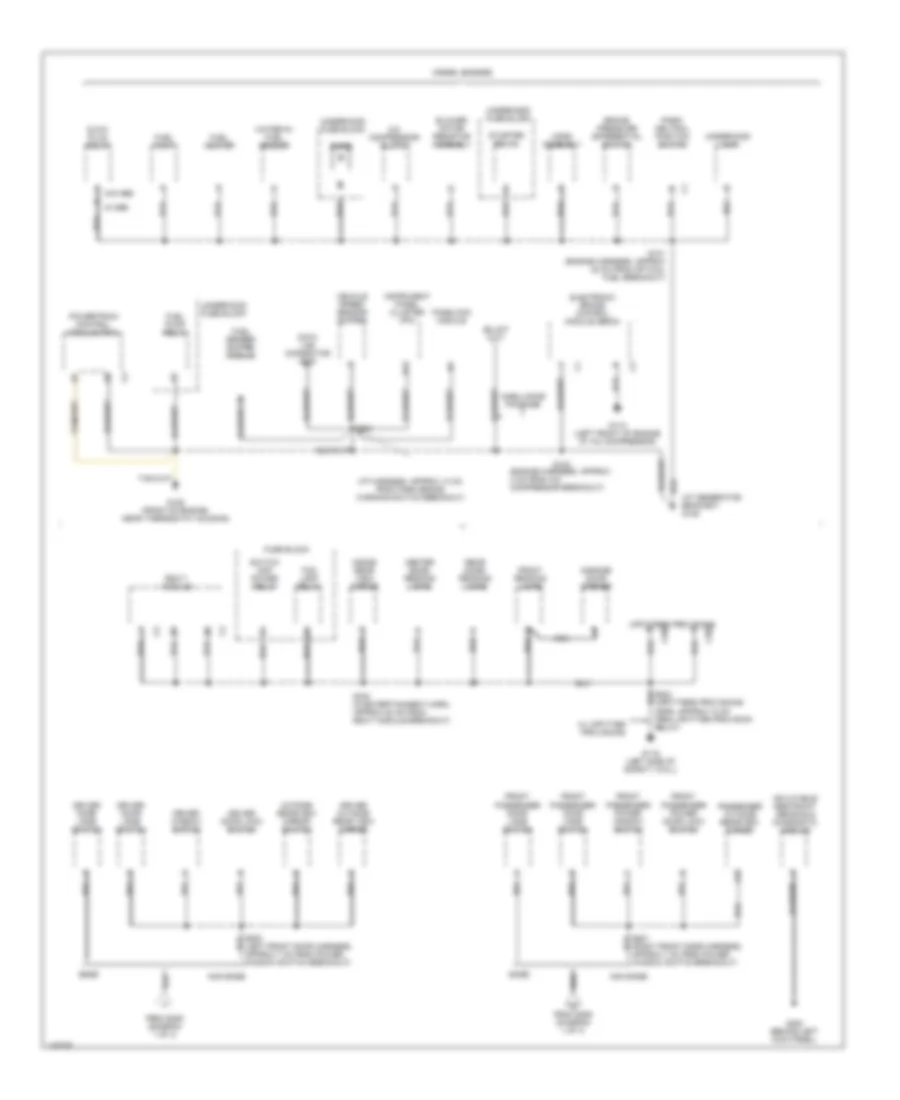
Ground Distribution Wiring Diagram (1 of 4) for Chevrolet Chevy Express G1500 2001

List of elements for Ground Distribution Wiring Diagram (1 of 4) for Chevrolet Chevy Express G1500 2001:
- (forward lamp harness, approx 19 cm into left forward lamp breakout)
- (forward lamp harness, approx 22 cm into right forward lamp breakout)
- (i/p harness, approx 7 cm into vss buffer breakout)
- (lower i/p harness, approx 7 cm into i/p compartment lamp breakout)
- (sun shade harness, approx 7 cm from right sun shade breakout)
- (w/ upfitter provisions)
- 31a
- A/t shift lock solenoid
- A12
- Accessory power outlet
- Air temperature actuator
- Auxiliary battery (diesel)
- Auxiliary blower motor
- Auxiliary blower motor switch
- Battery
- C200
- C202
- C210
- Cigar lighter
- Convenience center
- Convenience center (left side of dash)
- Coolant level module (diesel)
- Coolant level switch (diesel)
- Cruise test resistor connector
- Cruise test resistor connector (school bus only) b
- Data link connector
- Daytime running lamp (drl) control module
- Door jamb switch
- Door lock control module
- Door lock relay
- Driver seat adjuster switch
- E13
- Fog lamp switch
- Front passenger seat adjuster switch
- G100 (left side of engine compt, near fender well)
- G101 (right side of engine compt, near fender well)
- G113 (left frame rail, near auxiliary battery)
- G116 (left side of engine compt, under brake master cylinder)
- G118 (right lower front of engine)
- G119 (right frame rail, near front of engine)
- G200 (behind left kick panel)
- G404 (left rear side of cargo area)
- Headlamp leveling switch
- Headlamp switch
- Hvac control assembly
- I/p compartment lamp
- I/p relay block
- Ignition switch
- Instrument panel cluster (ipc)
- Interior lamp control module
- Left fog lamp
- Left front marker lamp
- Left front park/turn signal lamp
- Left headlamp (w/ sealed beam headlamps)
- Left headlamp leveling actuator
- Left high beam headlamp (w/ composite headlamps)
- Left low beam headlamp (w/ composite headlamps)
- Left rear fog lamp
- Left vanity mirror lamp
- Multi- function alarm module
- Nca
- Power brake (p/b) booster fluid alarm switch
- Radio
- Rear fog lamp switch
- Remote control door lock receiver
- Right fog lamp
- Right front marker lamp
- Right front park/turn signal lamp
- Right headlamp (w/ sealed beam headlamps)
- Right high beam headlamp (w/ composite headlamps)
- Right low beam headlamp (w/ composite headlamps)
- Right vanity mirror lamp
- S150 (approx 19 cm from left forward lamp breakout)
- S201 (i/p harness, approx 4 cm from park brake warning switch breakout)
- S202
- S204
- S205
- S206 (crossbody harness, approx 4 cm from power door lock relay breakout)
- S257 (power seat harn, under left side of dash)
- S328 (approx 80 cm from taillamp breakout)
- School bus equipment
- Seat belt switch
- Steering column ground
- To s500 or left front door jamb switch (diagram 2 of 4)
- To s601 or right front door jamb switch (diagram 2 of 4)
- Turn signal/ hazard flasher module
- Upfitter provisions relay
- W/ upfitter provisions
- W/o keyless entry
- Windshield washer pump motor
- Windshield wiper motor
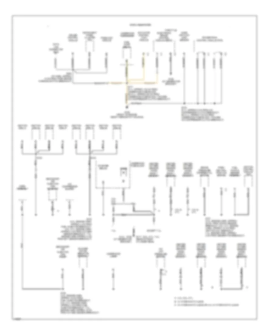
Ground Distribution Wiring Diagram (2 of 4) for Chevrolet Chevy Express G1500 2001
List of elements for Ground Distribution Wiring Diagram (2 of 4) for Chevrolet Chevy Express G1500 2001:
- (at generator bracket) g125
- (engine harness, approx 4 cm from a/c compressor breakout)
- (i/p harness, approx 10 cm from park brake warning switch breakout)
- (left front door harness, approx 7 cm from power window switch breakout)
- (right front door harness, approx 7 cm from power window switch breakout)
- A/c compressor clutch
- A18
- Ambulance package
- B13
- Base
- Blower motor resistor assembly
- Brake pressure differential switch
- C206
- C302
- Center dome/ reading lamps
- Data link connector (dlc)
- Diesel engines
- Diode
- Driver door jamb switch
- Driver door lock switch
- Driver outside rear view mirror
- Driver window switch
- Electronic brake control module (ebcm)
- Fog lamp relay
- From s206 (diagram 1 of 4)
- Front passenger door jamb switch
- Front passenger power door lock switch
- Front passenger power window switch
- Front reading lamps
- Fuel heater
- Fuel pump
- Fuel pump relay
- Fuel sender buffer module
- Fuse block
- G110 (left front of engine at a/c compressor)
- G116 (left side of safety wall)
- G125 (front of engine, near thermostat housing)
- G200 (behind left kick panel)
- Garage door opener
- Glow plug relay
- Horn assembly
- Inflatable restraint sensing & diagnostic module
- Inside rear view mirror
- Instrument panel cluster (ipc)
- Nca
- Non base
- Outside rearview mirror switch
- Park/ neutral position switch
- Passenger outside rearview mirror
- Passlock module
- Powertrain control module (pcm)
- Rear dome/ reading lamps
- Rsa-t module
- S101 (engine harness, approx 22 cm from optical fuel breakout)
- S102
- S254
- S330 (in entertainment harn, approx 20 cm from rsa-t module breakout)
- Starter relay
- Switch amp power relay
- Underhood fuse block
- Underhood lamp
- Upfitters provisions
- Vehicle speed sensor buffer
- W/ nb6
- W/ upfitter provisions
- W/o nb6
- Water-in- fuel sensor
Ground Distribution Wiring Diagram (3 of 4) for Chevrolet Chevy Express G1500 2001
List of elements for Ground Distribution Wiring Diagram (3 of 4) for Chevrolet Chevy Express G1500 2001:
- (4.3l)
- (5.0l, 5.7l, 7.4l)
- 4.3l & 5.7l
- 4.3l 5.0l 5.7l
- 4.3l, 5.0l, 5.7l a
- 7.4l
- A b 8.1l
- A/c compressor clutch
- A/c low pressure switch
- Actuator control (tac) module
- B13
- Blower motor resistor assembly
- Brake pressure differential switch
- Cruise control module
- Data link connector (dlc)
- Diode
- Electronic brake control module (ebcm)
- Except 7.4l
- Fuel pump & sender assembly
- Fuel pump relay
- G117 (rear of right cylinder head)
- G125 (at generator bracket)
- G125 (front of engine, near thermostat housing)
- Gasoline engines
- Heated oxygen sensor (ho2s) bank 1 sensor 1
- Heated oxygen sensor (ho2s) bank 1 sensor 2
- Heated oxygen sensor (ho2s) bank 2 sensor 1
- Heated oxygen sensor (ho2s) bank 2 sensor 2
- Horn assembly
- Ignition coil 1
- Ignition coil 2
- Ignition coil 3
- Ignition coil 4
- Ignition coil 5
- Ignition coil 6
- Ignition coil 7
- Ignition coil 8
- Ignition control module (icm)
- Instrument panel cluster (ipc)
- Mass air flow (maf) sensor
- Nca
- Park/ neutral position switch
- Passlock module
- Powertrain control module (pcm)
- S101 (4.3l: engine harn, approx 20 cm from knock sensor breakout, 5.0l, 5.7l: engine harn, approx 10 cm from ignition coil breakout, 7.4l: engine harn, approx 5 cm from generator breakout)
- S102 (8.1l- approx 5 cm from a/c compressor clutch breakout, ex 8.1l- approx 104 cm from underhood fuse block, toward a/c compressor clutch breakout)
- S103 (4.3l: engine harn, approx 4 cm from fuel injector breakout, 5.0l, 5.7l: engine harn, approx 4 cm from oxygen sensor breakout, 7.4l: engine harn approx 4 cm from ect sensor breakout)
- S152 (4.3l: engine harn, approx 16 cm from fuel injector breakout, 5.0l, 5.7l: engine harn, approx 4 cm from fuel injector breakout, 7.4l: engine harn approx 15 cm from oxygen sensor breakout)
- S171 (8.1l- approx 104 cm from underhood fuse block, ex 8.1l- approx 60 cm from underhood fuse block, toward a/c compressor clutch breakout)
- S183
- S184
- S254 (i/p harn, approx 10 cm from park brake warning switch breakout)
- Secondary air injection (air) pump
- Secondary air injection (air) solenoid
- Starter relay
- Throttle
- Underhood fuse block
- Underhood lamp
- W/ hydra-matic 4l60-e or 4.3l w/ hydra-matic 4l80-e c
- W/ hydra-matic 4l80-e b
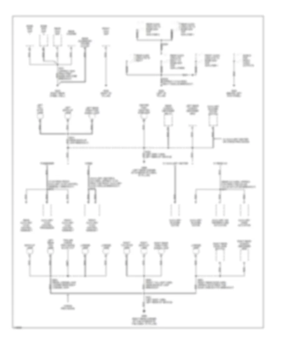
Ground Distribution Wiring Diagram (4 of 4) for Chevrolet Chevy Express G1500 2001
List of elements for Ground Distribution Wiring Diagram (4 of 4) for Chevrolet Chevy Express G1500 2001:
- (13 cm from front auxiliary hvac control assembly breakout) s318
- (approx 7.5 cm from rsa-t module breakout)
- (auxiliary heater & a/c harn, approx 14 cm from the front auxiliary hvac module breakout) s318
- (rear a/c harn, approx 5 cm from the o/s air valve actuator breakout) s411
- Auxiliary air temperature actuator
- Auxiliary blower motor
- Auxiliary blower motor switch
- Auxiliary hvac control processor
- Auxiliary mode actuator
- Back-up lamp
- Bare
- Bose amp
- Cargo
- Center high mounted stoplamp
- Front 100w amp
- Front audio circuits to bose 2000 amp amplifier 1
- Front auxiliary hvac control assembly
- G200 (behind left kick panel)
- G305 (right "b" pillar)
- G308 (left "b" pillar)
- G403 (right rear wheel well)
- G998 (right rear corner of the interior of the cabin, "d" pillar)
- G999 (left rear corner of interior of cabin, "d" pillar)
- Left back-up lamp
- Left rear fog lamp
- Left rear park/turn signal lamp
- Left rear window defogger grid
- Left tail/ stop lamp
- License lamp
- Passenger
- Rear 100w amp
- Rear accessory power outlet b
- Rear audio circuits rsa-t to bose 2000 amp ampllifiers
- Rear audio circuits to bose 2000 amp amplifier 1
- Rear audio circuits to bose 2000 amp amplifier 2
- Rear audio circuits to rsa-t
- Rear auxiliary hvac control assembly
- Rear window defogger relay
- Rear woofer
- Right back-up lamp
- Right rear door jamb switch
- Right rear park/turn signal lamp
- Right rear window defogger grid
- Right tail/stop lamp
- S331 (approx 16cm from first bose amplifier breakout)
- S394 bare
- S400 (left body harn, left rear of vehicle)
- S401 (left body harn, left rear of vehicle)
- S902 (rear license lamp jumper near right license lamp)
- S903 (right rear door harn, approx 29 cm from the door jamb switch breakout)
- S909 (right taillight harn, near back-up lamp breakout)
- S910 (near back-up lamp breakout)
- Shield for radio audio outputs
- W/ auxiliary heater
- W/ auxiliary heater or wiring provisions
- W/ rear a/c
- Wiring provisions