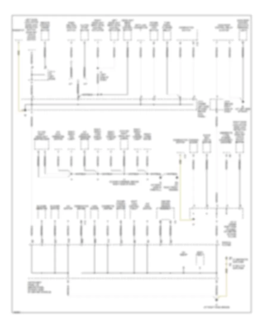
GROUND DISTRIBUTION
Ground Distribution Wiring Diagram, GT-S (1 of 2) for Toyota Celica GT 2004

List of elements for Ground Distribution Wiring Diagram, GT-S (1 of 2) for Toyota Celica GT 2004:
- (on left side of engine compt) engine room j/b
- (on left side of engine compt) engine room r/b 1
- (on left side of engine compt) engine room r/b 2
- (w/ hid) left head light control ecu
- A/c mag- netic clutch & lock sensor
- Air pump motor
- Auto antenna control relay
- Bk (at left side of liftback)
- Bl (at center of rear panel)
- Brake fluid level warning switch
- C12
- C16
- Camshaft position sensor shield
- Combi- nation meter
- Combination switch
- Crankshaft position sensor shield
- Data link connector
- Daytime running light resistor
- Door control receiver
- Drl 3 relay
- Drl 4 relay
- E1 (in engine harness, at left center of engine compartment)
- E1 (in engine harness, at left center of engine compartment)
- E1 (in engine harness, at left center of engine compt)
- E10
- E12
- Ec (at left side of cylinder head)
- Ed at left side of cylinder head
- Efi relay
- Em (at left front fender)
- En (right front of engine compartment)
- Engine con- trol module
- Engine control module
- Engine room j/b (on left side of engine compt)
- Eo (right front of engine compartment)
- F13
- F25
- F26
- Fan 2 relay
- Fuel pump
- Heated oxygen sensor (bank 1 sensor 1)
- Heated oxygen sensor (bank 1 sensor 1) shield
- Heated oxygen sensor (bank 1 sensor 2 shield
- Heated oxygen sensor (bank 1 sensor 2)
- High mounted stop light
- Htr relay
- I1 (in dash harness, behind center of dash)
- Ig2 relay
- Ignition coil & igniter
- J/c 1 (on left side of engine compt, forward of battery)
- J/c 14 (rear of left rear fenderwell)
- Knock sensor shield
- Left front fog light
- Left front parking light
- Left front side marker light
- Left front turn signal light
- Left head- light (low)
- Left license plate light
- Left rear combination light
- Nca
- Noise filter
- Radi- ator fan motor
- Rear window defogger
- Right license plate light
- Right rear combination light
- Skid control ecu w/ actuator
- W/o hid
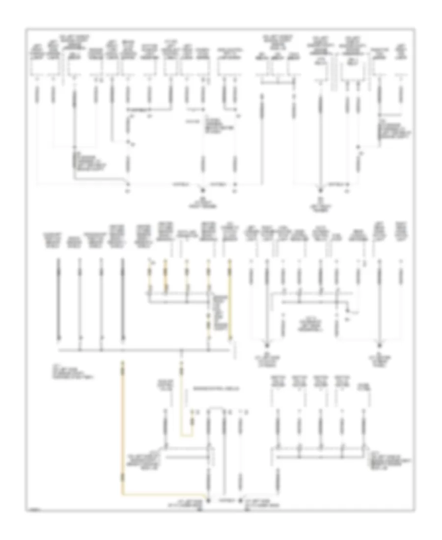
Ground Distribution Wiring Diagram, GT-S (2 of 2) for Toyota Celica GT 2004
List of elements for Ground Distribution Wiring Diagram, GT-S (2 of 2) for Toyota Celica GT 2004:
- (canada) clock
- (seperate type) stereo component amplifier
- (usa) clock
- (w/ hid) right headlight control ecu
- (w/o hid) right headlight (low)
- A/c dual pressure switch
- A/c single pressure switch
- A/c switch
- A/t
- Bi (at left side of roof)
- Blower resistor
- Blower switch
- Body ecu
- C12
- C15
- Center air bag sensor assembly
- Cigarette lighter
- Clutch start switch
- Combination meter
- Combination switch
- Data link connector
- Ea (at right front fender)
- F11
- Front wiper motor
- Glove box light & switch
- Headlight beam level control switch
- I12
- I4 (in dash harness, behind right side of dash)
- I5 (left side of dash)
- If (at right dash brace)
- Ig (at right side of firewall)
- Ig1 relay
- Instrument panel j/b (behind panel on right side of center console)
- J/c 10 (under right side of dash, on center of door pillar)
- J/c 11 (in left door)
- J/c 3 (under left side of dash, behind kick panel)
- J/c 9 (behind right side of dash)
- Left door lock motor door lock detection switch, door key lock & unlock switch
- Left headlight beam level control actuator
- M/t
- M10
- M20
- Moon roof control relay & motor
- Moon roof control switch & personal light
- O/d main switch
- P17
- P18
- Park/ neutral position switch
- Power window lock switch
- Power window master switch
- Radio & player
- Remote control mirror switch
- Rheostat
- Right door lock motor, door lock detection switch, door key lock & unlock switch
- Right front fog light
- Right front parking light
- Right front side marker light
- Right front turn signal light
- Right headlight beam level control actuator
- Shift lock control ecu
- Turn signal flasher relay
- W/ built-in amplifier
- W/ separate amplifier
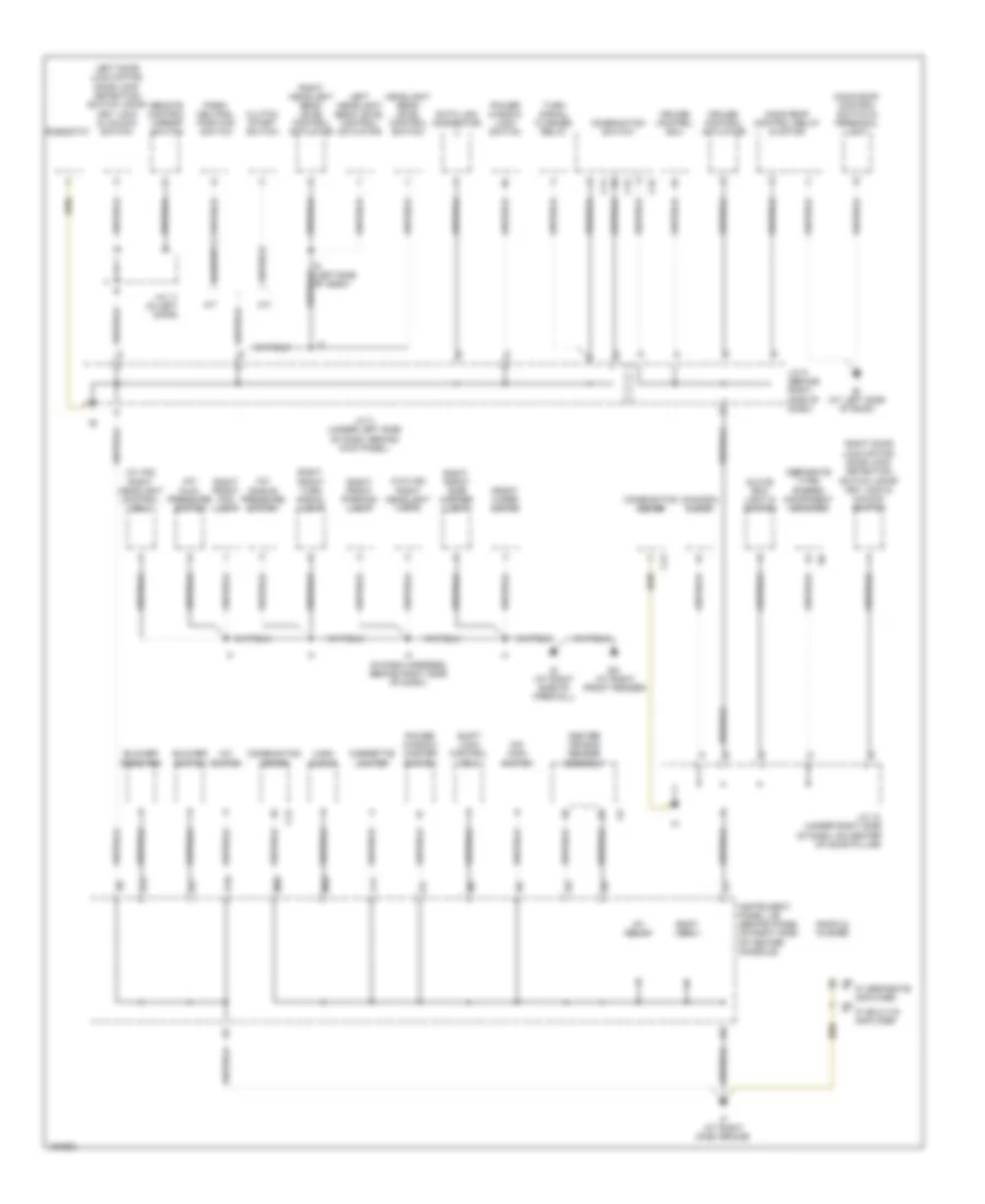
Ground Distribution Wiring Diagram, GT (1 of 2) for Toyota Celica GT 2004
List of elements for Ground Distribution Wiring Diagram, GT (1 of 2) for Toyota Celica GT 2004:
- (at left side of cylinder head) ec
- (at left side of cylinder head) ed
- (in engine harness, at left center of engine compt)
- (on left side of engine compt) engine room j/b
- (on left side of engine compt) engine room r/b 1
- (on left side of engine compt) engine room r/b 2
- (w/ hid) left headlight control ecu
- A/c magnetic clutch & lock sensor
- Auto antenna control relay
- Bk (at left side of hatch liftback)
- Bl (at center of rear panel)
- Brake fluid level warning switch
- C12
- Camshaft position sensor shield
- Combin- ation meter
- Crankshaft position sensor shield
- Data link connector
- Daytime running light resistor
- Door control receiver
- Drl 3 relay
- Drl 4 relay
- E1 (in engine harness, at left center of engine compt)
- Eb (at right front fender)
- Efi relay
- Em (at left front fender)
- Engine control module
- Engine room j/b (on left side of engine compt)
- F13
- F25
- F26
- F27
- Fan 2 relay
- Fuel pump
- Heated oxygen sensor (bank 1 sensor 1)
- Heated oxygen sensor (bank 1 sensor 1) shield
- Heated oxygen sensor (bank 1 sensor 2)
- Heated oxygen sensor (bank 1 sensor 2) shield
- High mounted stop light
- Htr relay
- I1 (in dash harness, behind center of dash)
- Idle air control valve
- Ig2 relay
- Ignition coil & igniter
- J/c 1 (on left side of engine compt, forward of battery)
- J/c 14 (on rear of left rear fenderwell)
- J/c 2 (on left side of engine compartment, beneath engine room j/b)
- J/c 2 (on left side of engine compt, beneath engine room j/b)
- Knock sensor shield
- Left front fog light
- Left front parking light
- Left front side marker light
- Left front turn signal light
- Left head- light (low)
- Left license plate light
- Left rear combi- nation light
- Nca
- Noise filter
- R11
- Radiator fan motor
- Rear window defogger
- Right license plate light
- Right rear combi- nation light
- Skid control ecu w/ actuator
- W/o hid
Ground Distribution Wiring Diagram, GT (2 of 2) for Toyota Celica GT 2004
List of elements for Ground Distribution Wiring Diagram, GT (2 of 2) for Toyota Celica GT 2004:
- (canada) clock
- (separate type) stereo component amplifier
- (usa) clock
- (w/ hid) right headlight control ecu
- (w/o hid) right headlight (low)
- A/c dual pressure switch
- A/c single pressure switch
- A/c switch
- A/t
- Bi (at left side of roof)
- Blower resistor
- Blower switch
- Body ecu
- C12
- C14
- C15
- C16
- Center air bag sensor assembly
- Cigarette lighter
- Clutch start switch
- Combination meter
- Combination switch
- Cruise control actuator
- Cruise control ecu
- Data link connector
- Ea (at right front fender)
- F11
- Front wiper motor
- Glove box light & switch
- Headlight beam level control switch
- I12
- I4 (in dash harness, behind right side of dash)
- If (at right dash brace)
- Ig (at right side of firewall)
- Ig1 relay
- Instrument panel j/b (behind panel on right side of center console)
- J/c 10 (under right side of dash, on center of door pillar)
- J/c 11 (in left door)
- J/c 3 (under left side of dash, behind kick panel)
- J/c 9 (behind right side of dash)
- Left door lock motor, door lock detection switch, door key lock & unlock switch
- Left headlight beam level control actuator
- M/t
- M10
- M20
- Moon roof control relay & motor
- Moon roof control switch & personal light
- O/d main switch
- Of dash)
- P17
- P18
- Park/ neutral position switch
- Power window lock switch
- Power window master switch
- Radio & player
- Remote control mirror switch
- Rheostat
- Right door lock motor, door lock detection switch, door key lock & unlock switch
- Right front fog light
- Right front parking light
- Right front side marker light
- Right front turn signal light
- Right headlight beam level control actuator
- Shift lock control ecu
- Turn signal flasher relay
- W/ built-in amplifier
- W/ separate amplifier