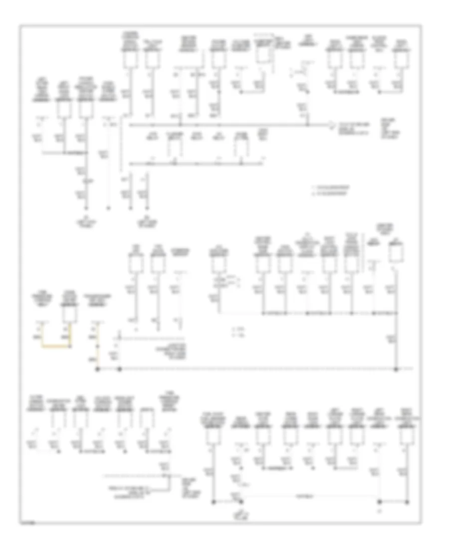
AUTOMOTIVE ELECTRICIANS PORTAL

GROUND DISTRIBUTION – Toyota Matrix S 2011 – SYSTEM WIRING DIAGRAMS

GROUND DISTRIBUTION

Ground Distribution Wiring Diagram (1 of 2) for Toyota Matrix S 2011

Ground Distribution Wiring Diagram (1 of 2) for Toyota Matrix S 2011 https://portal-diagnostov.com/license.html
https://portal-diagnostov.com/license.html Automotive Electricians Portal FZCO Automotive Electricians Portal FZCO
Download PDF file

List of elements for Ground Distribution Wiring Diagram (1 of 2) for Toyota Matrix S 2011:

  • (1.8l) cooling fan ecu
  • (1.8l) fan relay 1
  • (2.4l) cam position sensor shield
  • (2.4l) cooling fan motor
  • (2.4l) fan relay 2
  • (2.4l) oxygen sensor (bank 1 sensor 1) shield
  • (except usa) level warning switch assembly
  • (if equipped) 4wd ecu assembly
  • (left side of engine compt) engine room j/b
  • (left side of engine compt) engine room r/b
  • (w/ ptc heater) quick heater assembly
  • (w/o navigation) radio receiver assembly (w/ navigation) navigation receiver assembly
  • 1.8l
  • 2.4l
  • 2wd
  • 4wd
  • A1 (left front of engine compt)
  • A10
  • A13
  • A2 (left front of engine compt)
  • A23
  • A27
  • A28
  • A3 (right front of engine compt)
  • A37
  • A4 (right front of engine compt)
  • A5 (left end of dash)
  • A6 (right end of dash)
  • Ae5
  • Air fuel ratio sensor (bank 1 sensor 1) shield
  • Al2
  • Am2
  • B1 (2.4l) (rear of engine)
  • B2 (2.4l) (rear of engine)
  • B29
  • B3 (1.8l) (top of engine)
  • B4 (1.8l) (top of engine)
  • Ba2
  • Ba3
  • Blower resistor
  • Brake actuator assembly
  • Brake fluid level warning switch (brake master cylinder reservoir sub-assembly)
  • Canister pump module
  • Cigarette lighter assembly power point socket assembly
  • Crank position sensor shield
  • Daytime running light relay
  • Dlc 3
  • Door control receiver
  • Door control switch assembly
  • E10
  • E3 (right center of dash)
  • E4 (right kick panel)
  • E5 (left center of dash)
  • Ecm
  • Efi main relay
  • Engine room j/b (left side of engine compt)
  • Engine room r/b (left side of engine compt)
  • He1
  • Heater control sub- assembly
  • Htr sub relay 1
  • Htr sub relay 3
  • Ig2 relay
  • Ignition coil 1
  • Ignition coil 2
  • Ignition coil 3
  • Ignition coil 4
  • Junction connector a33 (left side of dash)
  • Knock control sensor (bank 1) shield
  • L17
  • Left fog light assembly
  • Left headlight assembly
  • M1 (right "c" pillar)
  • M2 (right "c" pillar)
  • Ms1
  • Mu1
  • Nca
  • Occupant detection ecu
  • Oxygen sensor (bank 1 sensor 2) shield
  • Power steering ecu assembly
  • Right fog light assembly
  • Right front door lock assembly
  • Right headlight assembly
  • Right outer rear view mirror assembly
  • Spiral cable (steering column)
  • Steering pad switch assembly
  • W/ ptc heater
  • W/ pulley compressor assembly
  • Windshield wiper motor assembly
  • Wireless door lock buzzer

Ground Distribution Wiring Diagram (2 of 2) for Toyota Matrix S 2011

Ground Distribution Wiring Diagram (2 of 2) for Toyota Matrix S 2011 https://portal-diagnostov.com/license.html
https://portal-diagnostov.com/license.html Automotive Electricians Portal FZCO Automotive Electricians Portal FZCO
Get access to all wiring diagrams of the carDownload PDF file

List of elements for Ground Distribution Wiring Diagram (2 of 2) for Toyota Matrix S 2011:

  • (2.4l & 2wd) trans- mission control switch
  • (center of dash) r/b 8
  • (diagram 2 of 2)
  • 1.8l
  • 2.4l
  • A/c amplifier assembly
  • Acc relay
  • Back door lock assembly
  • Center air bag sensor assembly
  • Center stop light assembly
  • Comb- ination meter assembly
  • Combination meter assembly
  • Dlc 3
  • Driver side j/b (left end of dash)
  • E1 (left kick panel)
  • E13
  • E14
  • E17
  • E18
  • E2 (left side of dash)
  • E28
  • E30
  • E73
  • Flasher relay
  • From k1 of driver side j/b a
  • Fuel pump fuel sender gauge (main) assembly
  • Hazard warning signal switch assembly
  • Headlight dimmer switch assembly
  • Heater control base sub- assembly
  • Htr relay
  • Ie1
  • Ig1 relay
  • Inner rear view mirror assembly
  • Inverter relay
  • Junction connector e64 (right side of dash)
  • Key inter lock solenoid
  • L2 (left "c" pillar)
  • Left front door lock assembly
  • Left license plate light assembly
  • Left outer rear view mirror assembly
  • Left rear combination light assembly
  • Main body ecu
  • Main switch assembly
  • Map light assembly
  • Noise filter
  • Outer mirror switch assembly
  • Pl1
  • Power outlet assembly
  • Power window regulator master switch assembly
  • Pwr relay
  • R/b 8 (center of dash)
  • Rear window defogger
  • Rear wiper motor assembly
  • Right license plate light assembly
  • Right rear combination light assembly
  • Room light 1 assembly
  • Room light 2 assembly
  • Shift lock control ecu sub- assembly
  • Sliding roof control ecu
  • St relay
  • Steering sensor
  • Telltale light assembly
  • Tire pressure warning ecu
  • Tire pressure warning reset switch
  • To m7 of driver side j/b (diagram 2 of 2)
  • Transponder key ecu assembly
  • Un-lock warning switch assembly
  • Voltage inverter assembly
  • Vsc off switch
  • W/ multi information display clock assembly
  • W/ sliding roof
  • W/o sliding roof
  • Wind- shield wiper switch assembly
  • Yaw rate sensor