GROUND DISTRIBUTION
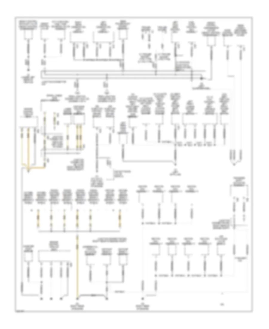
Ground Distribution Wiring Diagram (1 of 4) for Toyota Sequoia SR5 2010

List of elements for Ground Distribution Wiring Diagram (1 of 4) for Toyota Sequoia SR5 2010:
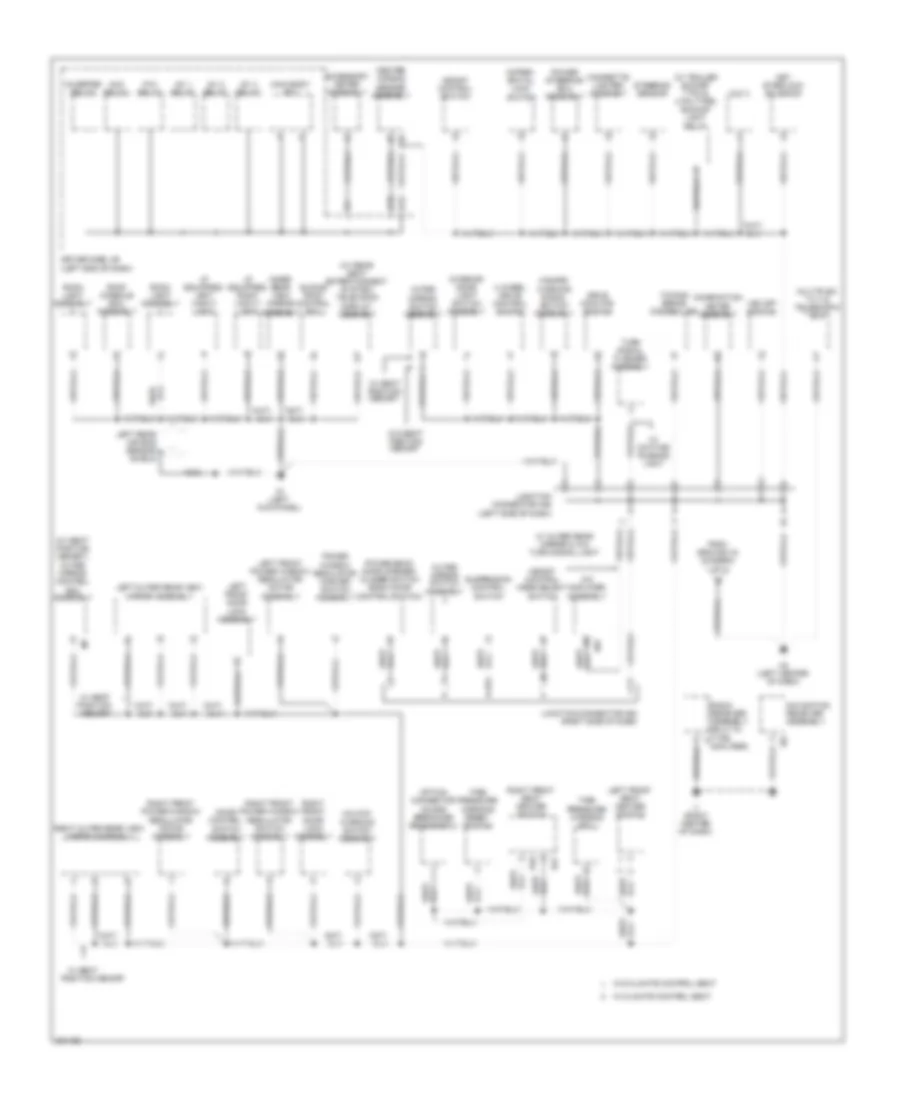
Ground Distribution Wiring Diagram (2 of 4) for Toyota Sequoia SR5 2010
List of elements for Ground Distribution Wiring Diagram (2 of 4) for Toyota Sequoia SR5 2010:
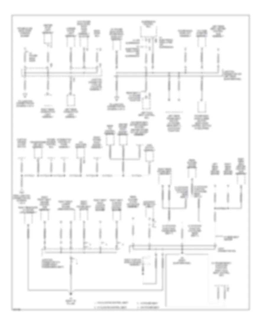
Ground Distribution Wiring Diagram (3 of 4) for Toyota Sequoia SR5 2010
List of elements for Ground Distribution Wiring Diagram (3 of 4) for Toyota Sequoia SR5 2010:
Ground Distribution Wiring Diagram (4 of 4) for Toyota Sequoia SR5 2010
List of elements for Ground Distribution Wiring Diagram (4 of 4) for Toyota Sequoia SR5 2010: