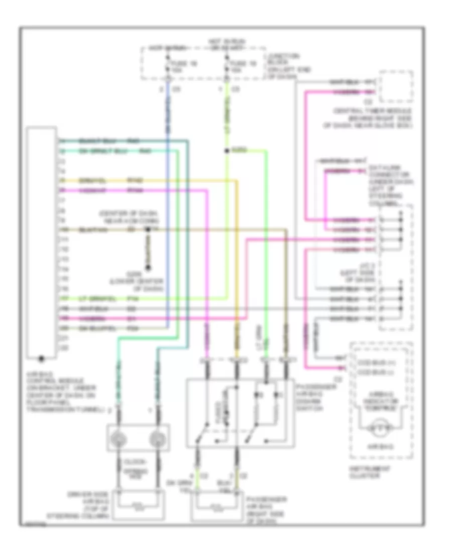
SUPPLEMENTAL RESTRAINTS
Supplemental Restraint Wiring Diagram for Dodge Dakota 1998
 https://portal-diagnostov.com/license.html
Automotive Electricians Portal FZCO
Automotive Electricians Portal FZCO
https://portal-diagnostov.com/license.html
https://portal-diagnostov.com/license.html
Automotive Electricians Portal FZCO
Automotive Electricians Portal FZCO
List of elements for Supplemental Restraint Wiring Diagram for Dodge Dakota 1998:
- (center of dash, near acm conn) s214
- (lower center of dash)
- Air bag
- Air bag control module (on bracket, under center of dash, on floor panel transmission tunnel)
- Airbag indicator control
- Ccd bus (+)
- Ccd bus (-)
- Central timer module (behind right side of dash, near glove box)
- Clock-
- Datalink connector (under dash, left of steering column)
- Driver side air bag (top of steering column)
- F14
- F24
- Fuse 18 10a
- Fuse 19 10a
- Fused resistor
- G206
- Hot in run
- Hot in run or start
- Instrument cluster
- J/c 3 (left side of dash)
- Junction block (on left end of dash)
- Nca
- Passenger air bag (right side of dash)
- Passenger air bag disarm switch
- R142
- R144
- R43
- R45
- S252
- Spring no2
 Čeština
 Dansk
Dansk Deutsch
 Ελληνικά
 English
 English
 Español
 Suomi
Suomi Français
 Français
 Hrvatski
 Magyar
 Italiano
 日本語
日本語 한국어
한국어 Nederlands
 Polski
 Português
 Português
 Română
 Русский
 Slovenčina
 Slovenščina
 Svenska
 Türkçe
 中文 (中国)
 עברית
עברית
