СИСТЕМА КОНДИЦИОНЕРА
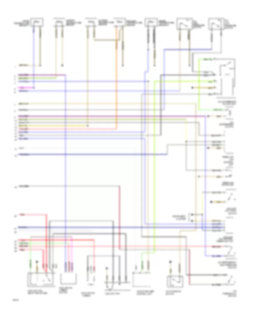
Электросхема кондиционера (1 из 2) для Audi 565 1991


Электросхема кондиционера (1 из 2) для Audi 565 1991 - Список элементов:
- (not used)
- A/c control head
- A/c programmer
- Alternator
- Battery
- Control pressure regulator
- Coolant fan relay #2
- Coolant fan relay #3
- Coolant pump thermo switch
- Cooling fan after run control unit
- Fuse 15a
- Fuse 21 25a
- Fuse 25a
- Fuse 30a
- Fuse 5a
- Fuse/ relay panel
- Hot w/ lights on
- Hot w/ load reduction relay energized
- Ignition(15)
- Ignition(35)
- Injector coolant fan
- Injector coolant fan relay
- Instrument cluster
- Interior temperature sensor 1 fan
- Red
- Temp regulator flap motor
- Thermo switch
- Turbo coolant pump
Электросхема кондиционера (2 из 2) для Audi 565 1991
Электросхема кондиционера (2 из 2) для Audi 565 1991 - Список элементов:
- A/c
- A/c compressor clutch
- A/c compressor clutch unit
- A/c high pressure switch
- A/c kickdown switch
- A/c refrigerant high pressure switch
- A/c thermostat switch
- Ambient temperature sensor
- Control unit
- Coolant fan
- Coolant fan control thermo switch
- Coolant fan relay-3rd stage
- Coolant low level
- Coolant temperature sensor
- Cooling fan
- Cooling fan thermo switch
- Fan
- Fresh air
- Fresh air fan motor
- Idle stabilizer control unit
- Inside temperature sensor 1
- Inside temperature sensor 2
- Instrument cluster
- Low pressure switch
- Outside temperature sensor
- Red
- Switch
- Thermo

 Čeština
 Dansk
Dansk Deutsch
 Ελληνικά
 English
 English
 Español
 Suomi
Suomi Français
 Français
 Hrvatski
 Magyar
 Italiano
 日本語
日本語 한국어
한국어 Nederlands
 Polski
 Português
 Português
 Română
 Русский
 Slovenčina
 Slovenščina
 Svenska
 Türkçe
 中文 (中国)