ENGINE PERFORMANCE
1.3L
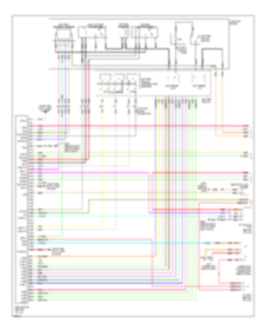
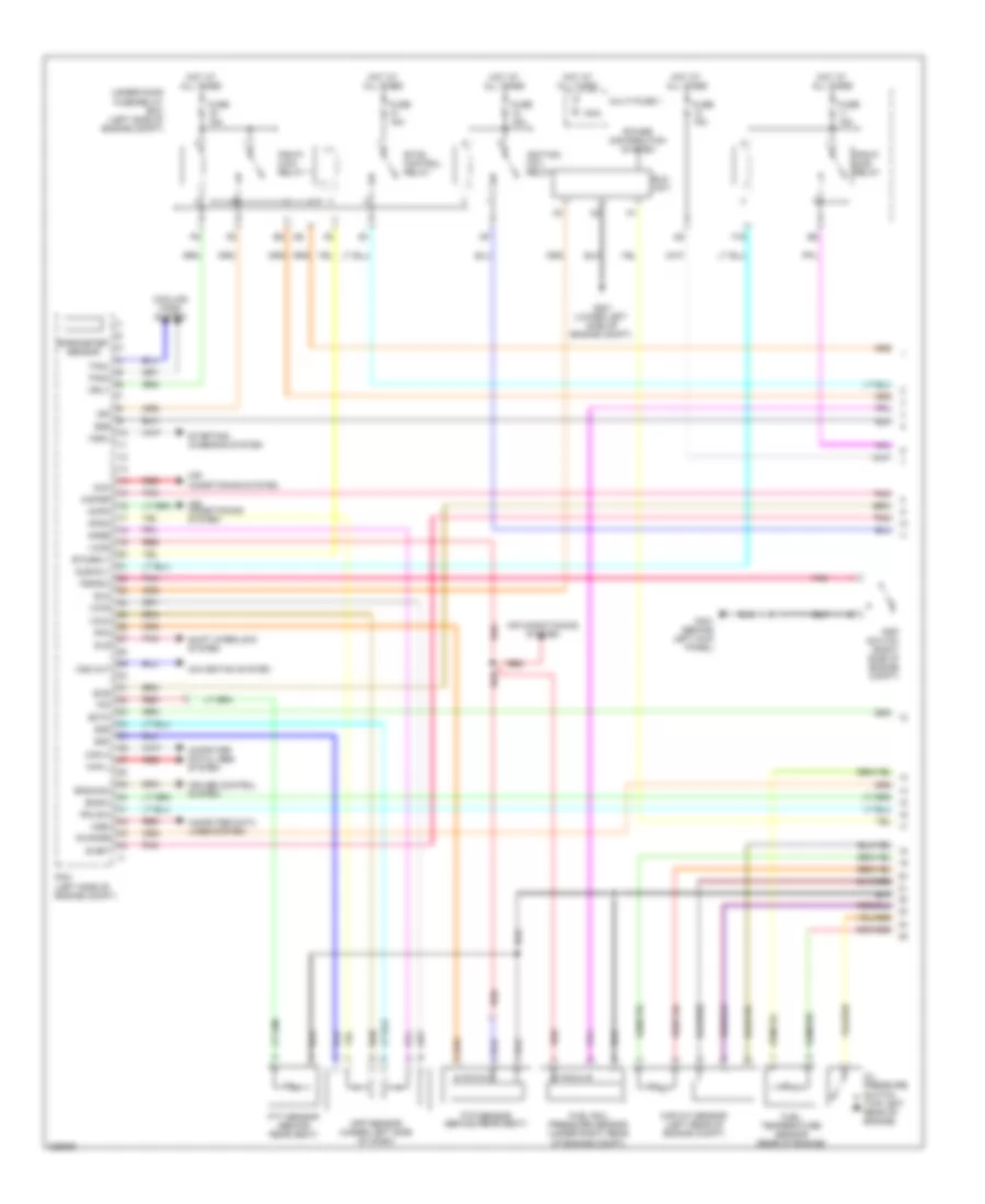
1.3L, Engine Controls Wiring Diagram (1 of 5) for Honda Civic LX 2010


List of elements for 1.3L, Engine Controls Wiring Diagram (1 of 5) for Honda Civic LX 2010:
- (lower front of engine compt) ect sensor 2
- (right side of engine compt) a/c pressure sensor
- (under left rear of vehicle) evap canister vent shut valve
- 100a
- Acc
- Acpd
- Air conditioning & cooling fans systems
- Air conditioning system
- Anti-theft system
- App sensor (under left side of dash)
- Apsa
- Apsb
- B15
- Barometer sensor
- Bksw
- Bkswnc
- Can-h
- Can-l
- Computer data lines system
- Cooling fans system
- Ect2
- Eld
- Eld unit
- Eps control unit (under right end of dash)
- Etcsrly
- F16
- F19
- Fanh
- Fanl
- Ftp
- Ftp sensor
- Fuse 15a
- G301 (lower left side of engine compt)
- Hot at all times
- Igp1
- Igp2
- Imacanh
- Imacanl
- Imoflr
- J/c c101 (left rear corner of engine compt)
- Mrly
- Multi- fuse 1
- Navigation system
- Nep
- Pcm (left side of engine compt)
- Pgm-fi sub- relay
- Pnk
- Power distribution system
- Red
- S-net
- Scs
- Sg3
- Sg4
- Sg5
- Shift interlock system
- Sls
- Starting/charging system
- Starting/charging system cruise control system
- Stc
- Sts
- Sub rly
- Under- hood fuse/ relay box (left rear of engine compt)
- Vcc4
- Vcc5
- Vcc6
- Vssout
- Vsv
- Wen
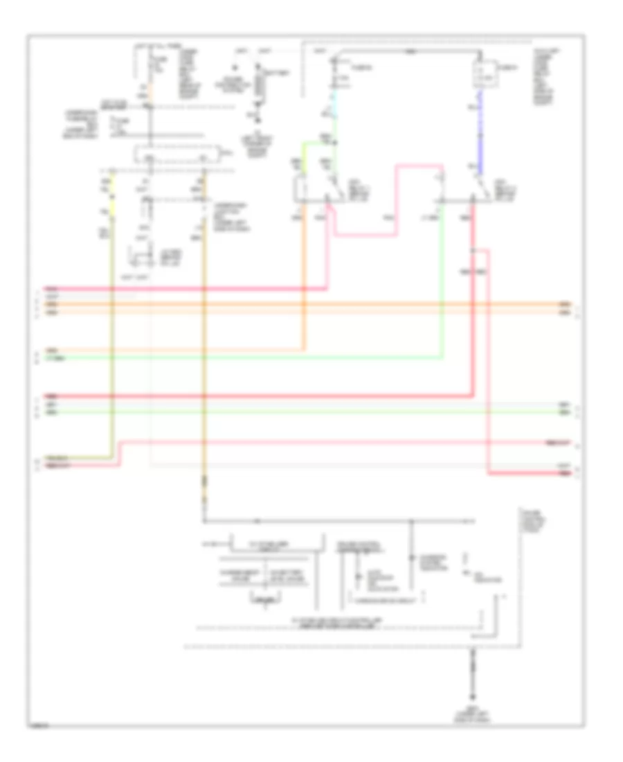
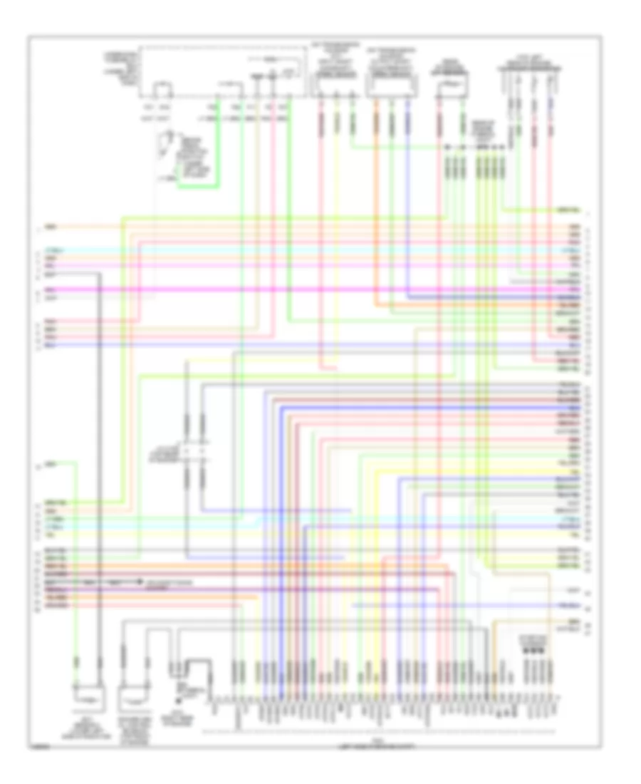
1.3L, Engine Controls Wiring Diagram (2 of 5) for Honda Civic LX 2010
List of elements for 1.3L, Engine Controls Wiring Diagram (2 of 5) for Honda Civic LX 2010:
- (not used)
- 5v stabilize circuit/controller area network controller
- A/t gear position dimming circuit
- A/t gear position indicator drive circuit
- At-p
- Atp-r
- Compulsory turninf-off circuit
- Computer data lines system
- Cvt drive pulley pressure control valve
- Cvt driven pulley pressure control valve
- Cvt start clutch pressure control valve
- F-can transceiver
- F27
- Fail-safe circuit
- Fuse 7.5a
- G102 (left side of engine)
- G504 (under left side of dash)
- Gauge control module (tach)
- Hot in on or start
- Iat sensor
- Ig1
- Ind mil
- Inhibitor solenoid
- J/c c101 (left rear corner of engine compt)
- J14
- K14
- Maf sensor
- Maf/iat sensor (on engine air intake duct)
- Micu
- Oil pressure switch (near oil filter)
- Pnk
- Red
- S2 (thermal joint)
- Transmission range switch (on transmission housing)
- Under-dash fuse/relay box (under left end of dash)
- Under-dash junction box (under left side of dash)
- Warning drive circuit
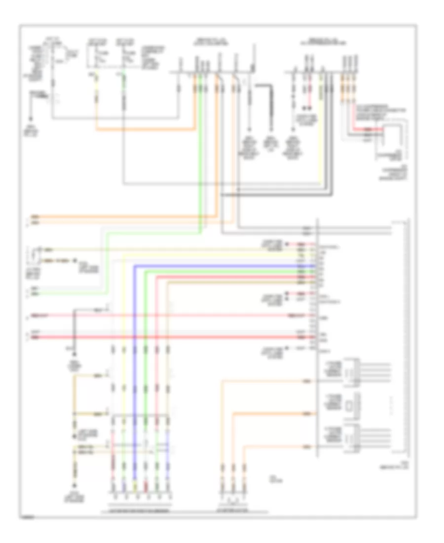
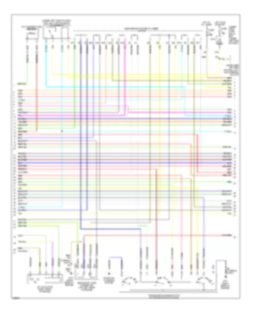
1.3L, Engine Controls Wiring Diagram (3 of 5) for Honda Civic LX 2010
List of elements for 1.3L, Engine Controls Wiring Diagram (3 of 5) for Honda Civic LX 2010:
- (right rear of engine) ect sensor 1
- (right rear of engine) evap canister purge valve
- (thermal joint) s1
- (top front of engine) egr valve & egr valve position sensor
- (top left rear of engine) rocker arm oil control solenoid 1
- (top left rear of engine) rocker arm oil control solenoid 2
- A/f sensor connector (top of transmission housing)
- Atp fwd
- Atpd
- Atpl
- Atpn
- Atpp
- Atpr
- Atps
- Cvt pg1
- Cvt pg2
- Dnls (+)
- Dnls (-)
- Drls (+)
- Drls (-)
- Ect1
- Egr p
- Erg
- Fuse 10a
- G101 (top left side of engine)
- G102 (left side of engine)
- Hot in on or start
- Iat
- Inhsol
- J/c c101 (left rear corner of engine compt)
- Ndr
- Opsw
- Pcm (left side of engine compt)
- Pcs
- Pg1
- Pg2
- Pnk
- Red
- S1 (thermal joint)
- S2 (thermal joint)
- S4 (thermal joint)
- S6 (thermal joint
- Scls (+)
- Scls (-)
- Secondary ho2s connector (top of transmission housing)
- Sg2
- So2shtc
- Under-dash fuse/relay box (under left end of dash)
- Vcc2
- Vg (+)
- Vg (-)
- Vts1
- Vts2
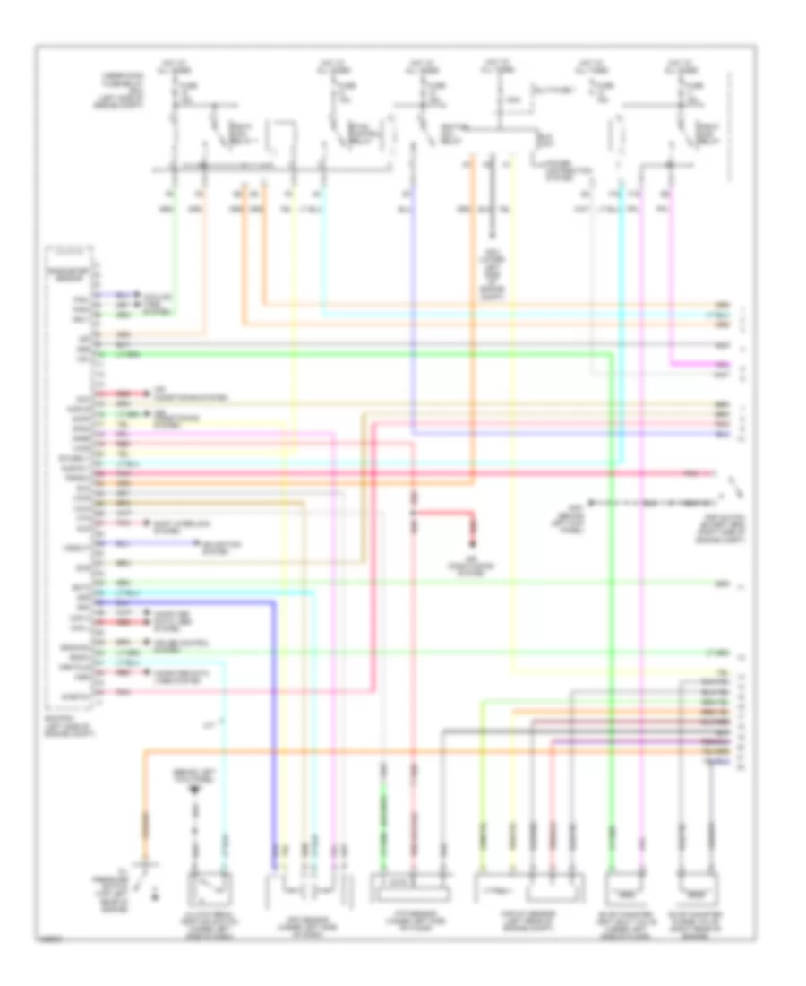
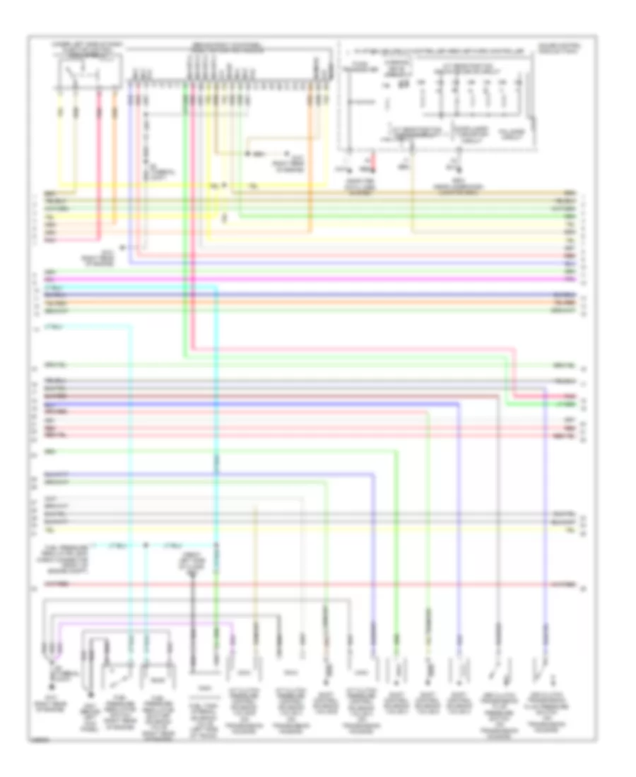
1.3L, Engine Controls Wiring Diagram (4 of 5) for Honda Civic LX 2010
List of elements for 1.3L, Engine Controls Wiring Diagram (4 of 5) for Honda Civic LX 2010:
- A21
- Auxiliary under-hood fuse/ relay box (left side of engine compt)
- B18
- Brake pedal position switch (top of brake pedal assembly)
- Ckp sensor (lower right front of engine)
- Cmp sensor (right rear of engine)
- Cvt drive pulley speed sensor (on transmission housing)
- Cvt driven pulley speed sensor (on transmission housing)
- Cvt speed sensor (on transmission housing)
- Eop sensor (top left rear of engine)
- Etcs control relay
- F10
- F25
- F30
- F31
- Fuel pump
- Fuel tank unit (inside fuel tank)
- Fuse 15a
- G102 (left side of engine)
- G16
- G601 (on left side of floor)
- Hot at all times
- J/c c101 (left rear corner of engine compt)
- J/c c105 (top right rear of engine)
- Map sensor (left rear side of engine)
- Pgm-fi main relay 2
- Red
- Rocker arm oil pressure switch (top left rear of engine)
- S3 (thermal joint)
- S4 (thermal joint)
- S5 (thermal joint) (left side of engine)
- To pgm-fi main relay 1 (diagram 5 of 5)
- Tp sensor/throttle actuator (top right rear of engine)
- Under- hood fuse/ relay box (left rear of engine compt)
- Under-dash fuse/relay box (under left end of dash)
1.3L, Engine Controls Wiring Diagram (5 of 5) for Honda Civic LX 2010
List of elements for 1.3L, Engine Controls Wiring Diagram (5 of 5) for Honda Civic LX 2010:
- (left side of engine) g102
- (thermal joint) s2
- (top left side of engine) injectors
- A16
- A18
- A22
- A23
- Afs (+)
- Afs (-)
- Afshtc
- B16
- B17
- B21
- B23
- Ckp
- Cmp
- E10
- Etcsm (+)
- Etcsm (-)
- F24
- From etcs control relay a (diagram 4 of 5)
- Front ignition coils (top left side of engine)
- Fuse 15a
- Fuse 20a
- G102 (left side of engine)
- G11
- Hot at all times
- Hot in on or start
- Icm
- Ig1
- Ig1etcs
- Ignition coil relay
- Igpls1
- Igpls1e
- Igpls2e
- Igpls2i
- Igpls31
- Igpls3e
- Igpls4e
- Igpls4i
- Igrtne
- Igrtni
- Inj1
- Inj2
- Inj3
- Inj4
- J/c c101 (left rear corner of engine compt)
- J/c c105 (top right rear of engine)
- J/c c106 (top rear of engine)
- Knock sensor (near oil filter)
- Lg1
- Lg2
- Map
- Ndn
- Pcm (left side of engine compt)
- Pgm-fi main relay 1
- Pgmetcs
- Poilcs
- Rear ignition coils (top right side of engine)
- Red
- S1 (thermal joint)
- S2 (thermal joint)
- Sg1
- Sg3
- Sho2s
- Tpsa
- Tpsb
- Under- hood fuse/ relay box (left rear of engine compt)
- Under-dash fuse/relay box (under left end of dash)
- Vcc1
- Vcc3
- Vel
- Vtpsw
1.3L, IMA Wiring Diagram (1 of 3) for Honda Civic LX 2010
List of elements for 1.3L, IMA Wiring Diagram (1 of 3) for Honda Civic LX 2010:
- (+)
- (-)
- (behind ipu lid) j/c c902
- (left side of engine) g102
- 100a
- A10
- A11
- A12
- A13
- A14
- A15
- A16
- A17
- A18
- A19
- A20
- A21
- A22
- A23
- A24
- A25
- A26
- A27
- A28
- A29
- A30
- A31
- A32
- A33
- A34
- A35
- A36
- A37
- A38
- A39
- A40
- B10
- B11
- B12
- B13
- B14
- Batteries 1-12
- Batteries 13-22
- Battery current sensor
- Battery module
- Battery module fuse
- Battery module switch
- Battery module temperature sensors
- Bcm module (behind ipu lid)
- Bypass contractor
- Bypass resistor
- Can h
- Can-l
- Cnt
- Cntpg
- Computer data lines system
- Dlc (under left side of dash)
- E16
- Fanctl
- G902 (behind right side of rear seat back)
- High voltage connector
- Ig1
- Iga2
- Ighld
- Ighld2
- Imacanh
- Imacanl
- Ipu module fan (behind ipu lid)
- Isoc +
- Isoc -
- J/c c902 (behind ipu lid)
- Junction board
- Lg2
- Nca
- Nfan
- Pg2
- Pnk
- Pre
- Red
- Scibd
- Scidb
- Scs
- Sg1soc
- Sgtb
- Tbatt1
- Tbatt2
- Tbatt3
- Under-dash junction box (under left side of dash)
- Vbu
- Vcc1soc
- Vhb0
- Vhb1
- Vhb10
- Vhb11
- Vhb12
- Vhb2
- Vhb3
- Vhb4
- Vhb5
- Vhb6
- Vhb7
- Vhb8
- Vhb9
- Wen
1.3L, IMA Wiring Diagram (2 of 3) for Honda Civic LX 2010
List of elements for 1.3L, IMA Wiring Diagram (2 of 3) for Honda Civic LX 2010:
- 10a
- 10v stabilizer circuit
- 5v stabilize circuit/controller area network controller
- 7.5a
- Auto idle stop ind (auto stop)
- Auxiliary under- hood fuse/ relay box (left side of engine compt)
- Battery
- Charge/assist gauge
- Charging system indicator
- Cruise control dimming circuit
- Driver
- E18
- E28
- Fuse 10a
- Fuse 61
- Fuse 62
- Fuse 7.5a
- G1 (left front corner of engine compt)
- G504 (under left side of dash)
- Gauge control module (tach)
- Hot at all times
- Hot in on or start
- Ig1
- Ima battery level gauge
- Ima indicator
- J/c c903 (behind ipu lid)
- J14
- K14
- Mcm relay 1 (behind ipu lid)
- Mcm relay 2 (behind ipu lid)
- Micu
- Nca
- Pnk
- Power distribution system
- Red
- Under- hood fuse/ relay box (left rear of engine compt)
- Under-dash fuse/relay box (under left end of dash)
- Under-dash junction box (under left side of dash)
- Vbu
- Warning drive circuit
1.3L, IMA Wiring Diagram (3 of 3) for Honda Civic LX 2010
List of elements for 1.3L, IMA Wiring Diagram (3 of 3) for Honda Civic LX 2010:
- (behind ipu lid) a/c compressor driver
- (behind ipu lid) dc-dc converter
- (left side of engine) g102
- 100a
- 12 volt
- A/c compressor (front of engine compt)
- A/c compressor motor
- A/c compressor power cable connector (middle rear of engine compt)
- Braided wire
- Can h
- Can l
- Computer data lines system
- Fuse 10a
- Fuse 7.5a
- G102 (left side of engine)
- G901 (behind right side of rear seat back)
- G902 (behind right side of rear seat back)
- G903 (under mcm)
- G904 (behind ipu lid)
- G904 (behind left ipu lid)
- Gnd
- Hi volt (+)
- Hi volt (-)
- Hot at all times
- Hot in on or start
- Ig1
- Iga2
- Ignition
- Ima can l
- Ima canh
- Ima f-can h
- Ima f-can l
- Ima motor
- J/c c902 (behind ipu lid)
- Lg2
- Mcm (behind ipu lid)
- Motor rotor position sensor
- Multi- fuse
- Nca
- Red
- Scidb
- Starter motor
- U phase
- U phase motor current sensor
- Under- hood fuse/ relay box (left rear of engine compt)
- Under-dash fuse/relay box (under left end of dash)
- V phase
- V phase motor current sensor
- Vbu
- W phase
- W phase motor current sensor
- Wen
1.8L
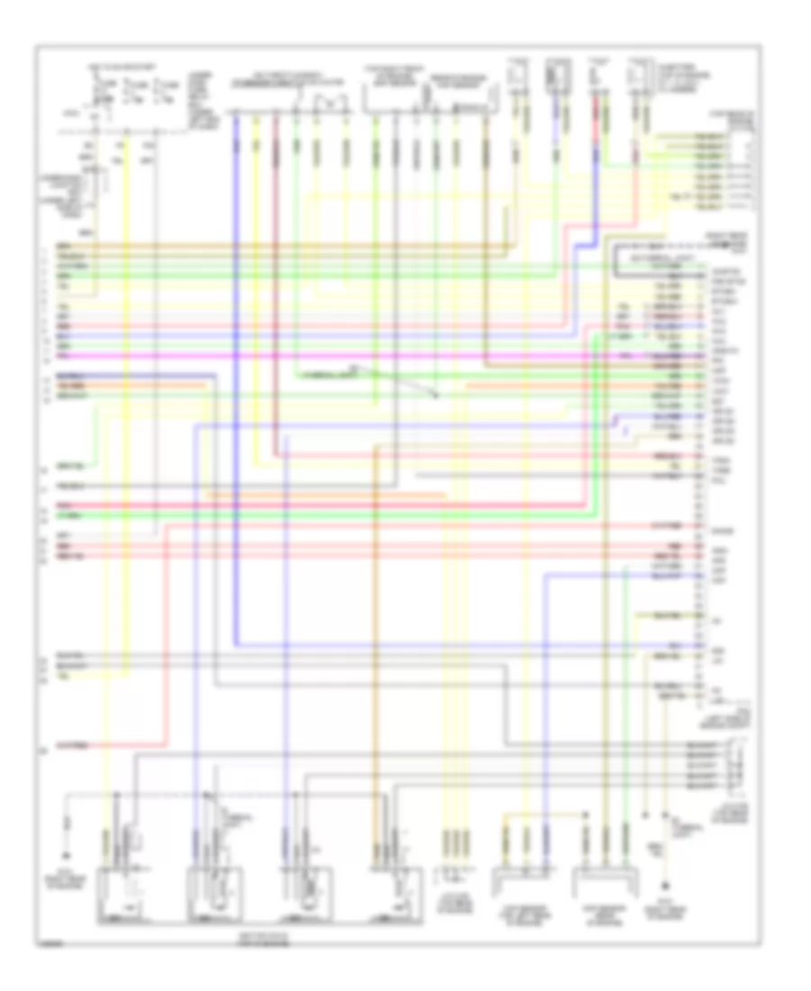
1.8L, Engine Controls Wiring Diagram, Except GX (1 of 5) for Honda Civic LX 2010
List of elements for 1.8L, Engine Controls Wiring Diagram, Except GX (1 of 5) for Honda Civic LX 2010:
- (behind left kick panel) g401
- 100a
- Acc
- Acpd
- Air conditioning system
- App sensor (under left side of dash)
- Apsa
- Apsb
- Barometer sensor
- Bksw
- Bkswnc
- Can h
- Can l
- Clutch pedal position switch (under left side of dash)
- Computer data lines system
- Cooling fans system
- Crmtcls
- Cruise control system
- Ecm/pcm (left side of engine compt)
- Ect2
- Eld
- Eld unit
- Etcs control relay
- Etcsrly
- Evap canister purge valve (right rear of engine)
- Evap canister vent shut valve (under left side of floor)
- F16
- F19
- Fanh
- Fanl
- Ftp
- Ftp sensor (under left side of floor)
- Fuse 15a
- G301 (lower left side of engine compt)
- G401 (behind left kick panel)
- Hot at all times
- Ignition coil relay
- Igp
- Imoflr
- M/t
- Maf/iat sensor (left rear of engine compt)
- Mrly
- Multi-fuse 1
- Navigation system
- Oil pressure switch (top left rear of engine)
- Pgm-fi main relay 1
- Pgm-fi sub- relay
- Pnk
- Power distribution system
- Psp switch (except eps) (right side of engine compt)
- Pspsw
- Red
- S-net5v
- Scs
- Sg4
- Sg5
- Sg6
- Shift interlock system
- Sls
- Sub rly
- Under-hood fuse/relay box (left side of engine compt)
- Vcc4
- Vcc5
- Vcc6
- Vssout
- Vsv
- Wen
1.8L, Engine Controls Wiring Diagram, Except GX (2 of 5) for Honda Civic LX 2010
List of elements for 1.8L, Engine Controls Wiring Diagram, Except GX (2 of 5) for Honda Civic LX 2010:
- (front left side of floor) g601
- (in top of fuel tank)
- (on transmission housing) (a/t) input shaft (mainshaft) speed sensor
- (on transmission housing) output shaft (countershaft) speed sensor
- (rear of engine) (terminal joint) s4
- (rear of engine) ect sensor 1
- (top left rear of engine) a/f sensor connector
- Altc
- Altf
- Altl
- Atft
- Atp fwd
- Atp- p
- Atp2-1
- Atpd
- Atpd3
- Atpn
- Atpp
- Atpr
- Atprvs
- Brake pedal position switch (under left side of dash)
- Ecm/pcm (left side of engine compt)
- Ect sensor 2 (lower left side of radiator)
- Ect1
- Egr
- Egr p
- Eps control unit (if equipped) (behind right kick panel)
- F10
- F11
- F25
- F27
- F30
- F31
- Fuel pump
- Fuel tank unit
- Fuse 15a
- G101 (right rear rear of engine)
- G16
- Hot in on or start
- Iat
- Imt +
- Imt -
- Imtm
- J/c c105 (top rear of engine)
- J/c c207 (right rear of engine compt)
- Lsa
- Lsb
- Lsc
- Micu
- Op2sw
- Op3sw
- Opsw
- Pcs
- Pg1
- Pg2
- Pgm-fi main relay 2
- Pnk
- Red
- Rocker arm oil control solenoid (top front of engine)
- S- net
- Scs
- Sg2
- Sha
- Shb
- Shc
- Shd
- So2shtc
- Starting/ charging system
- Under-dash fuse/relay box (under left end of dash)
- Vcc2
- Vg+
- Vg-
- Vts
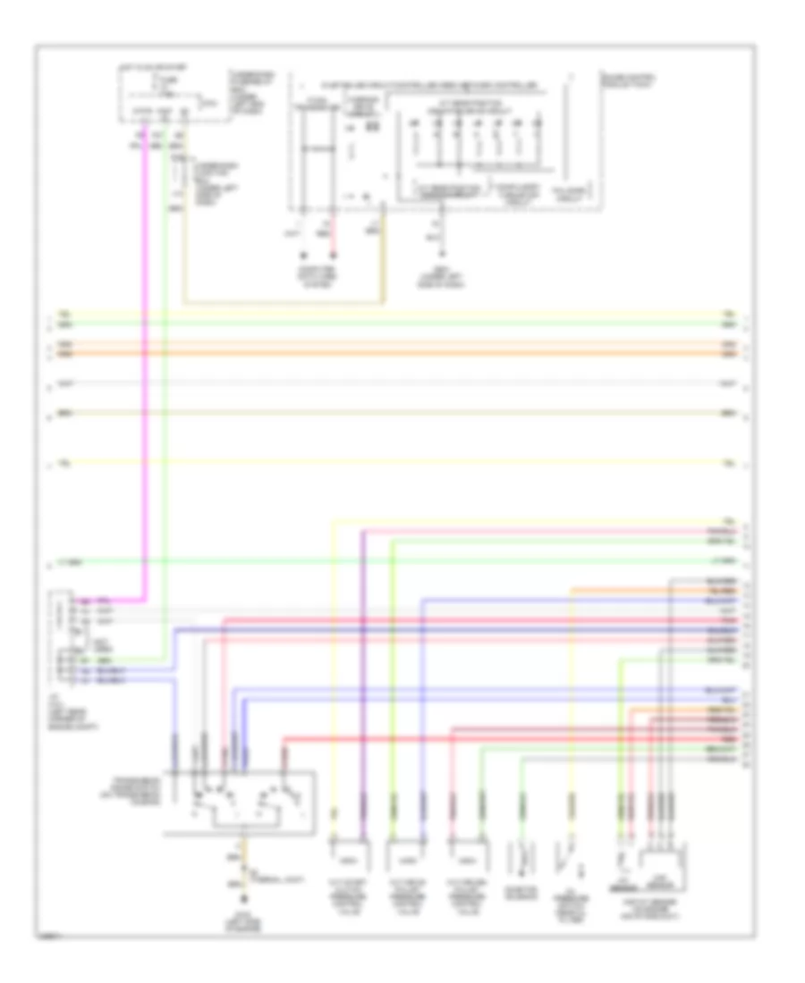
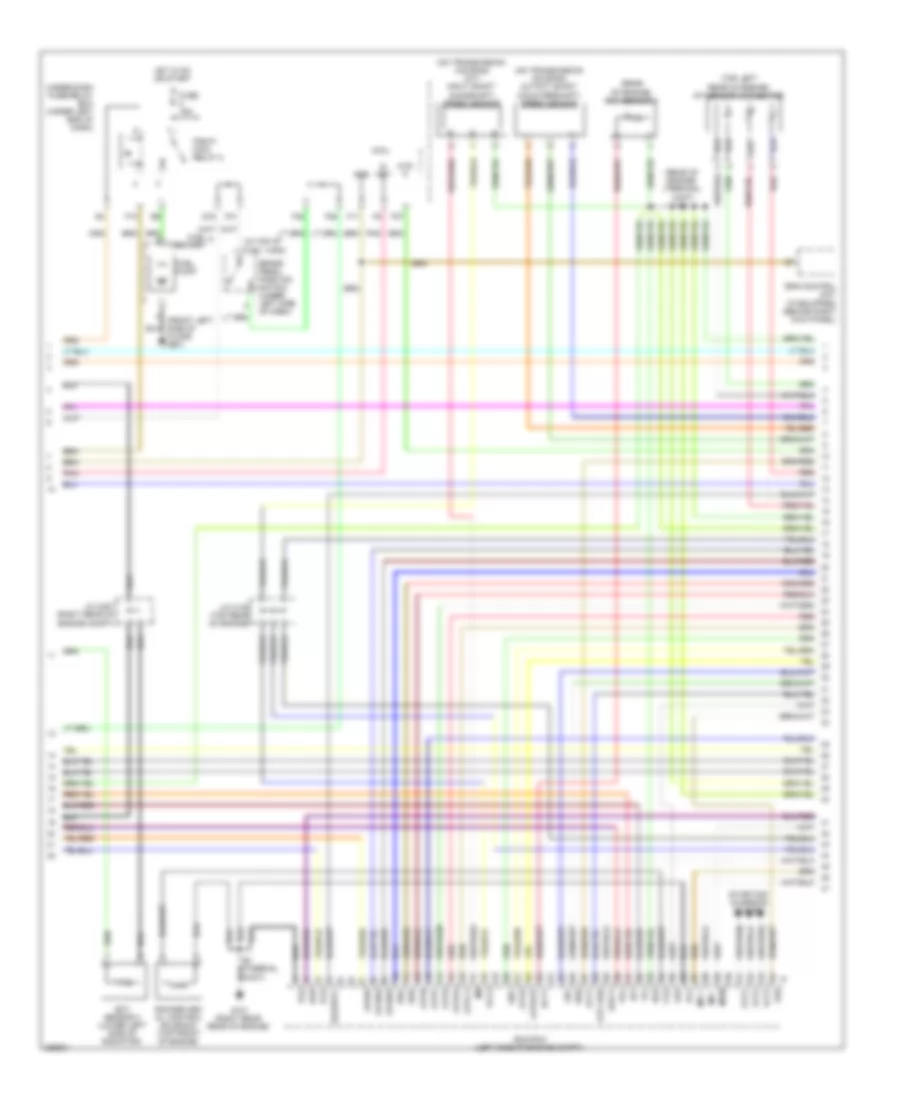
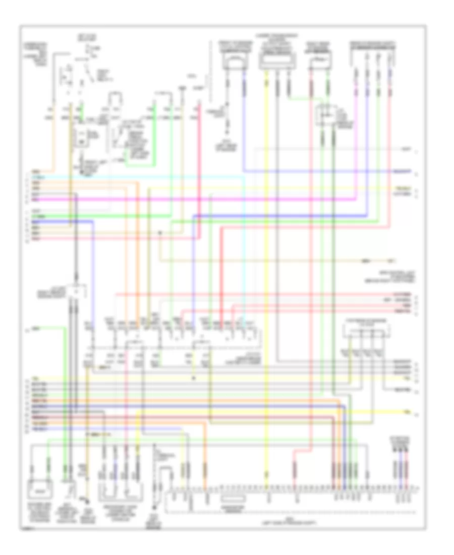
1.8L, Engine Controls Wiring Diagram, Except GX (3 of 5) for Honda Civic LX 2010
List of elements for 1.8L, Engine Controls Wiring Diagram, Except GX (3 of 5) for Honda Civic LX 2010:
- (near brake master cylinder) junction connector c101
- (thermal joint) s3
- 2-1
- A16
- A21
- A22
- A23
- Atf temperature sensor
- B15
- B16
- B17
- B18
- B23
- G101 (right rear of engine)
- Imt actuator (right front of engine)
- Pnk
- Red
- Secondary ho2s connector (top left rear of engine)
- Starting/ charging system
- Transmission range switch (on transmission housing)
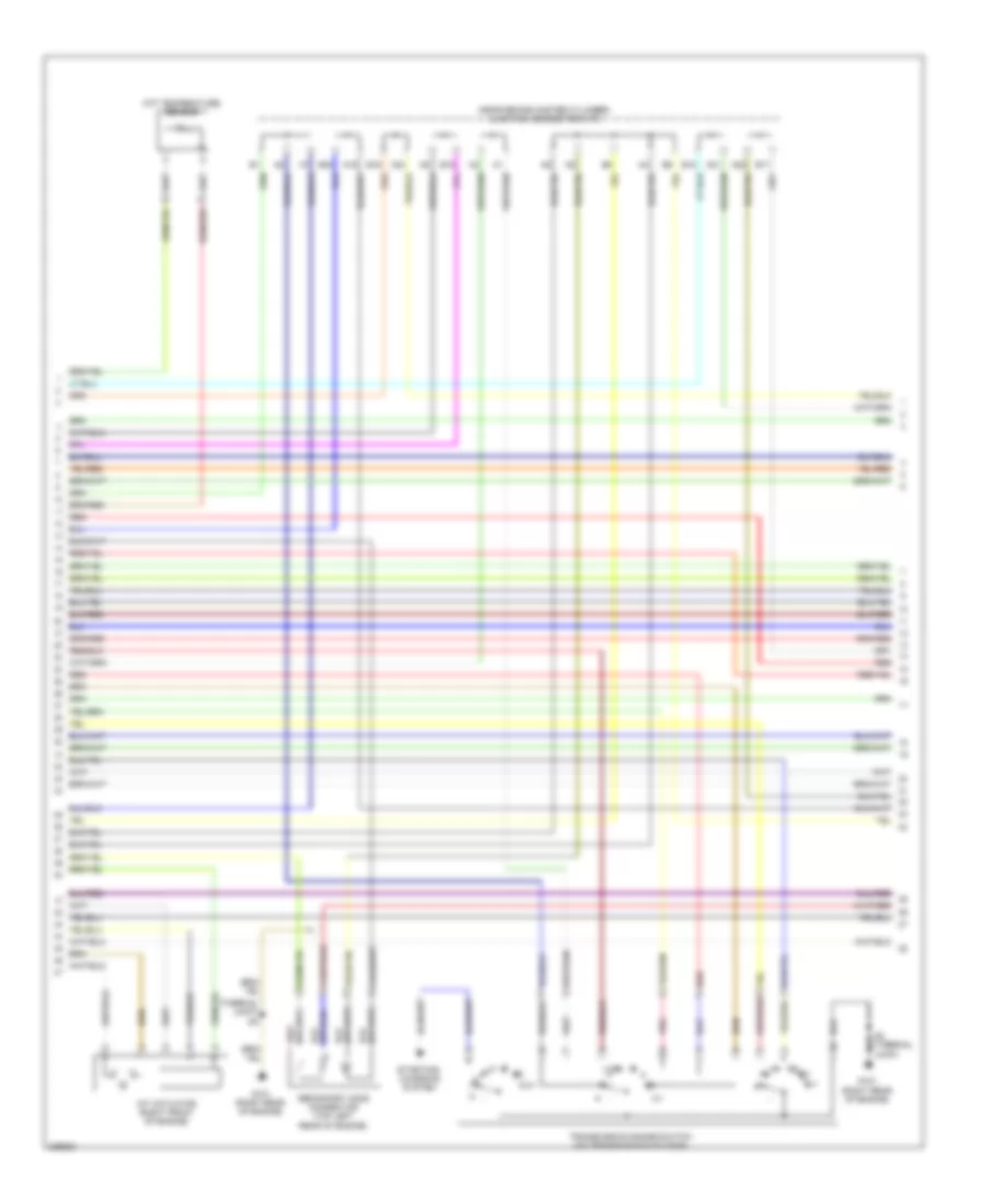
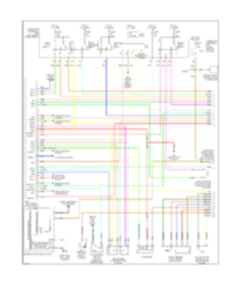
1.8L, Engine Controls Wiring Diagram, Except GX (4 of 5) for Honda Civic LX 2010
List of elements for 1.8L, Engine Controls Wiring Diagram, Except GX (4 of 5) for Honda Civic LX 2010:
- (if equipped) power window master switch
- 2 door
- 2nd clutch transmission fluid pressure switch (on transmission housing)
- 3rd clutch transmission fluid pressure switch (on transmission housing)
- 5v stabilize circuit/ controller area network controller
- A/t clutch pressure control solenoid valve a (on transmission housing)
- A/t clutch pressure control solenoid valve b (on transmission housing)
- A/t clutch pressure control solenoid valve c (on transmission housing)
- A/t gear position dimming circuit
- Circuit drive
- Compulsory turninf-off circuit
- Computer data lines system
- Fail-safe circuit
- Fuse 7.5a
- G101 (right rear of engine)
- G504 (near under-dash junction box)
- Gauge control module (tach)
- Hot in on or start
- Ig1
- Indicator drive circuit a/t gear position
- J14
- K14
- Micu
- Mil ind
- Red
- S2 (thermal joint)
- Shift control solenoid valve a
- Shift control solenoid valve b
- Shift control solenoid valve c
- Shift control solenoid valve d
- Transceiver f-can
- Under-dash fuse/relay box (under left end of dash)
- Under-dash junction box (under left side of dash)
- Warning
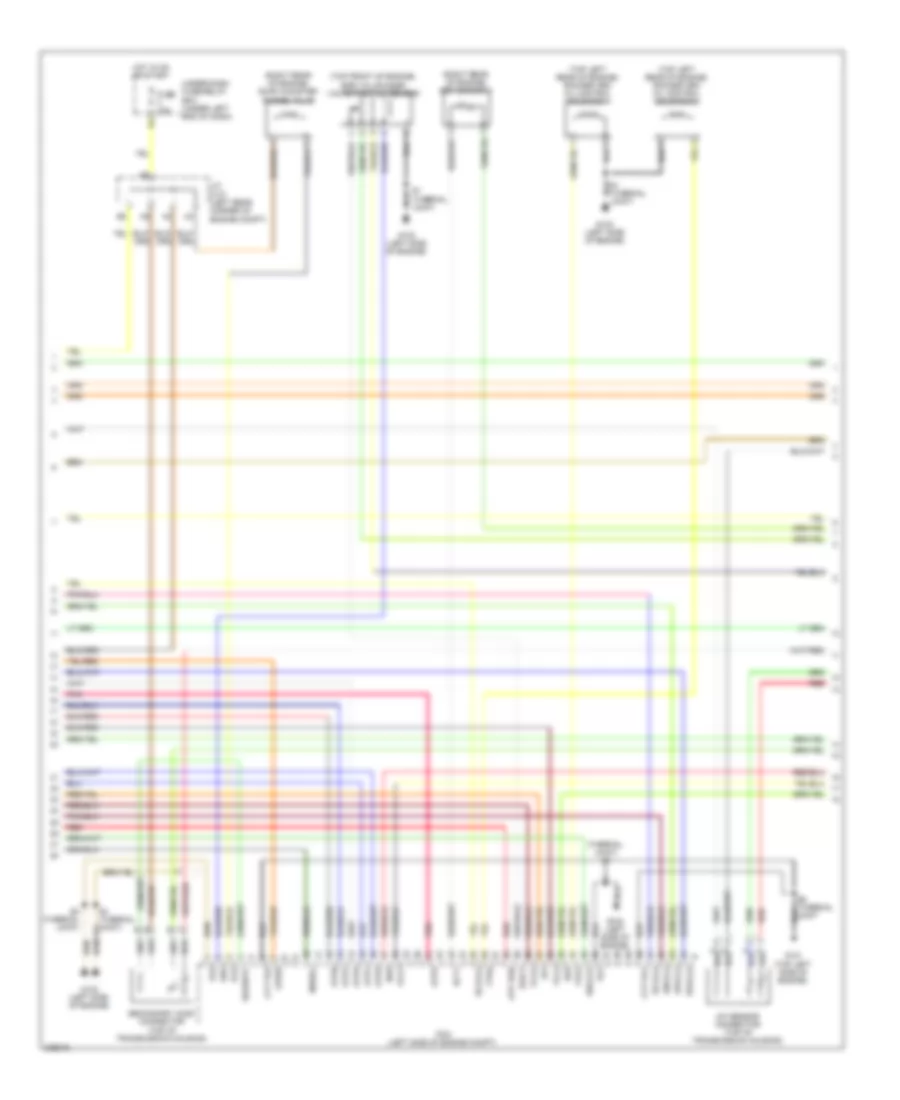
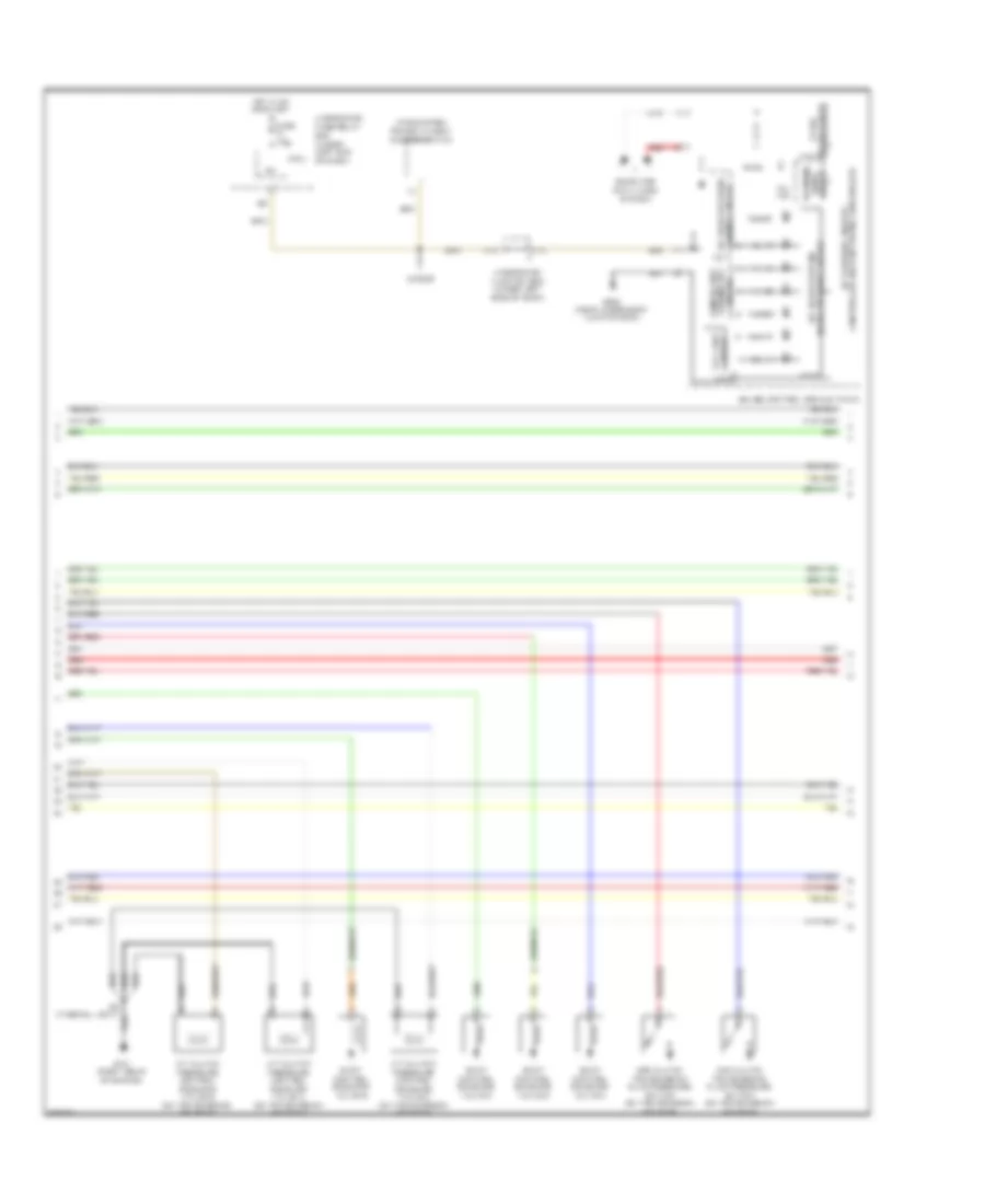
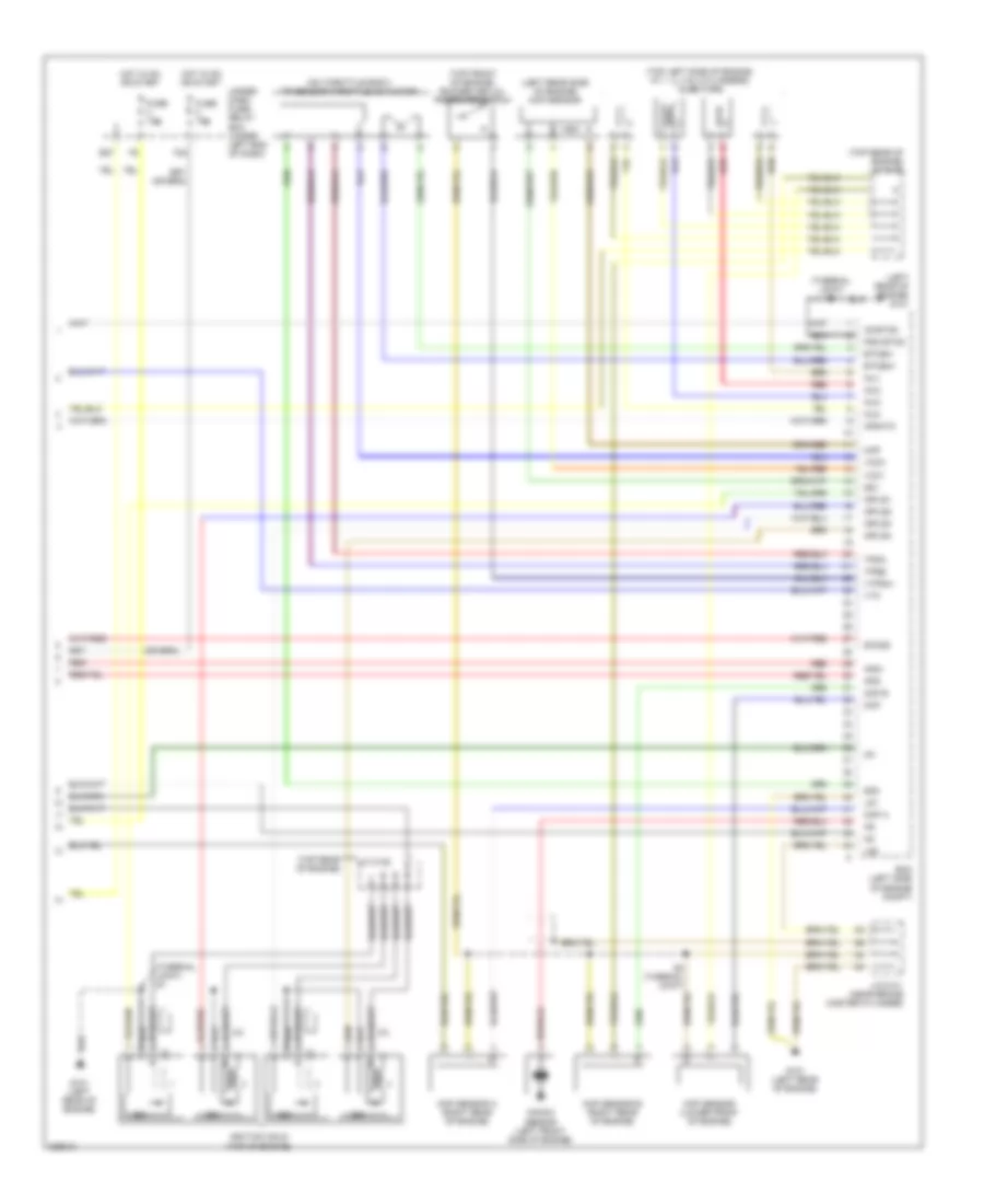
1.8L, Engine Controls Wiring Diagram, Except GX (5 of 5) for Honda Civic LX 2010
List of elements for 1.8L, Engine Controls Wiring Diagram, Except GX (5 of 5) for Honda Civic LX 2010:
- (on throttle body) tp sensor/throttle actuator
- (rear of engine) map sensor
- (right rear of engine) g101
- (thermal joint) s2
- (top rear of engine) j/c c105
- (top right front of engine) eop sensor
- Afs+
- Afs-
- Afshtc
- Ckp
- Ckp sensor (top left rear of engine)
- Cmp
- Cmp sensor (rear of engine)
- Ecm/pcm (left side of engine compt)
- Egr valve & egr valve position sensor (top left rear of engine)
- Etcsm+
- Etcsm-
- F24
- Fuse 10a
- Fuse 15a
- G101 (right rear of engine)
- Hot in on or start
- Icm
- Ig1
- Ig1etcs
- Ignition coils (top of engine)
- Igpls1
- Igpls2
- Igpls3
- Igpls4
- Inj1
- Inj2
- Inj3
- Inj4
- Injectors (top of engine, at 1, 2, 3 & 4 cylinders)
- J/c c105 (top rear of engine)
- Knock sensor (lower right rear of engine)
- Lg1
- Lg2
- Map
- Pgm etcs
- Poil
- Red
- S1 (thermal joint)
- S5 (thermal joint)
- Sg1
- Sg3
- Sho2s
- Tpsa
- Tpsb
- Under- dash fuse/ relay box (under left end of dash)
- Vcc1
- Vcc3
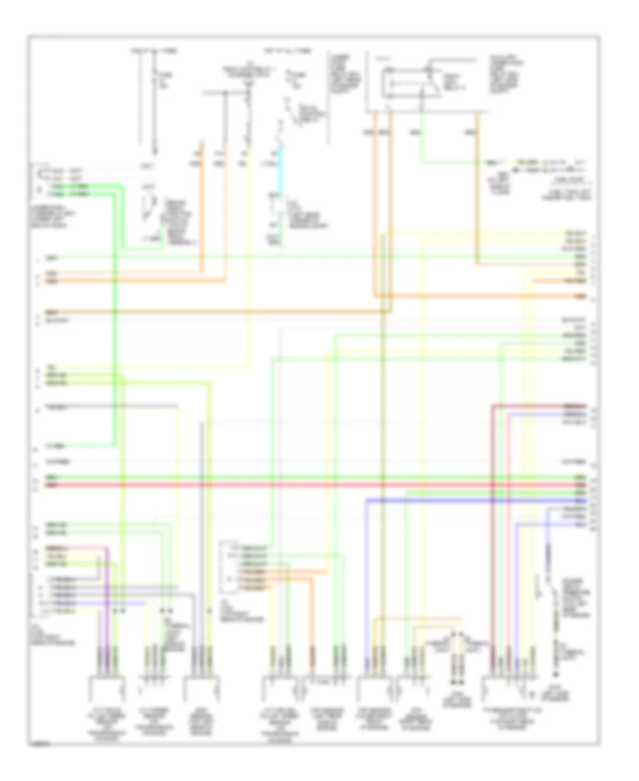
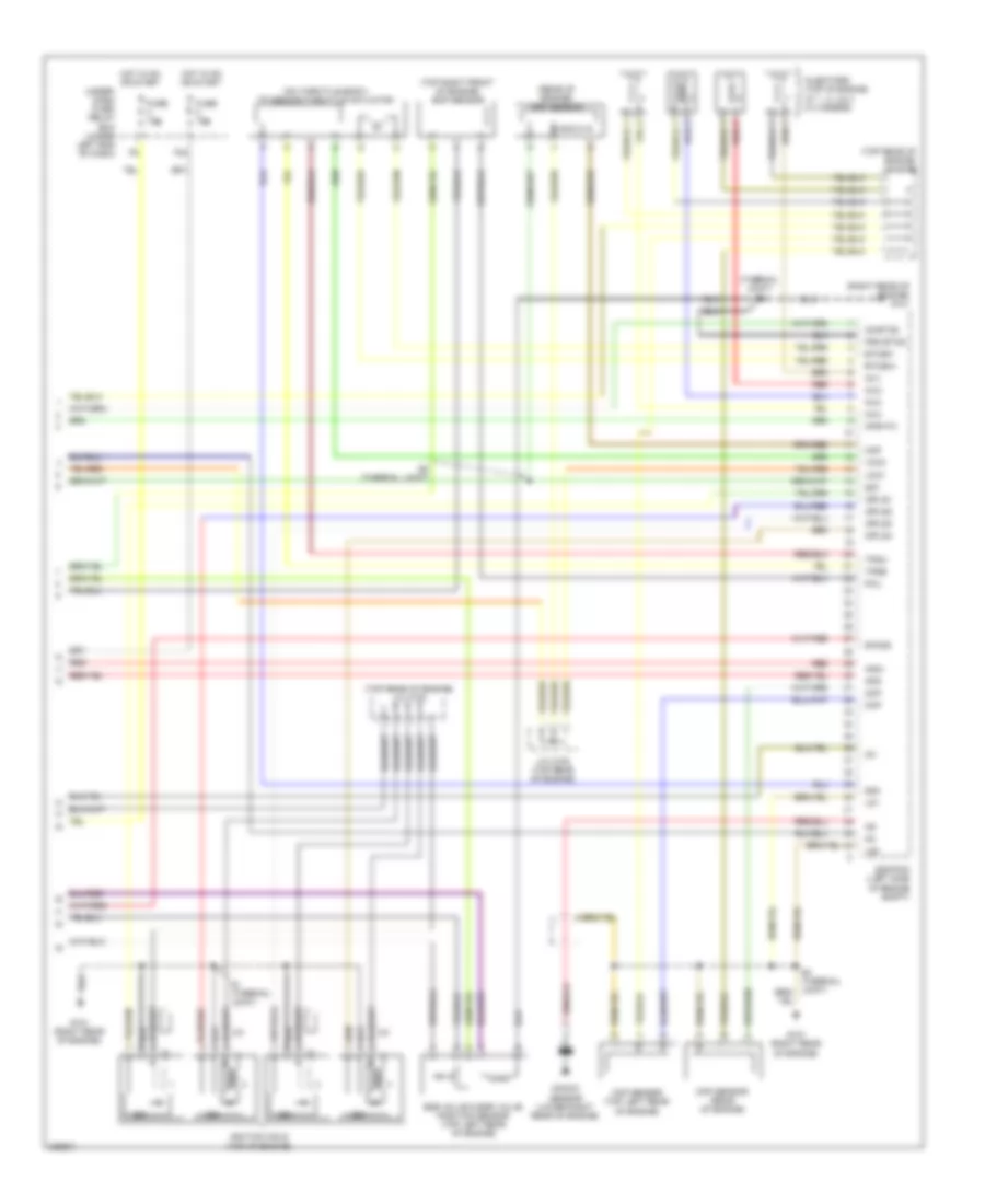
1.8L, Engine Controls Wiring Diagram, GX (1 of 5) for Honda Civic LX 2010
List of elements for 1.8L, Engine Controls Wiring Diagram, GX (1 of 5) for Honda Civic LX 2010:
- 100a
- Acc
- Acpd
- Air conditioning system
- App sensor (under left side of dash)
- Apsa
- Apsb
- Barometer sensor
- Bksw
- Bkswnc
- Can h
- Can l
- Computer data lines system
- Cooling fans system
- Cruise control system
- Ect2
- Eld
- Eld unit
- Etcs control relay
- Etcsrly
- F16
- Fanh
- Fanl
- Ftp sensor (behind rear seat)
- Ftt sensor (behind rear seat)
- Fuel rail pressure sensor (under right rear of engine compt)
- Fuel temperature sensor (rear of engine)
- Fuse 15a
- G301 (lower left side of engine compt)
- G401 (behind left kick panel)
- Hot at all times
- Ignition coil relay
- Igp
- Imofsr
- Injmode
- Maf/iat sensor (left rear of engine compt)
- Mrly
- Multi-fuse 1
- Navigation system
- Oil pressure switch (top left rear of engine)
- Pcm (left side of engine compt)
- Pf2 sw
- Pfo
- Pgm-fi main relay 1
- Pgm-fi sub- relay
- Pnk
- Power distribution system
- Psp switch (right side of engine compt)
- Pspsw
- Red
- S-net
- Scs
- Sg4
- Sg5
- Sg6
- Shift interlock system
- Sls
- Starting/ charging system
- Sub rly
- Tf0
- Under-hood fuse/relay box (left side of engine compt)
- Vcc4
- Vcc5
- Vcc6
- Vss out
- Vssv
- Wen
1.8L, Engine Controls Wiring Diagram, GX (2 of 5) for Honda Civic LX 2010
List of elements for 1.8L, Engine Controls Wiring Diagram, GX (2 of 5) for Honda Civic LX 2010:
- (on transmission housing) (a/t) input shaft (mainshaft) speed sensor
- (on transmission housing) output shaft (countershaft) speed sensor
- (rear of engine) (thermal joint) s4
- (rear of engine) ect sensor 1
- (top left rear of engine) a/f sensor connector
- Air conditioning system
- Altc
- Altf
- Altl
- Atft
- Atp- p
- Atp2-1
- Atpd
- Atpd3
- Atpfwd
- Atpn
- Atpp
- Atpr
- Atprvs
- Brake pedal position switch (under left side of dash)
- Ect sensor 2 (lower left side of radiator)
- Ect1
- F11
- F25
- F27
- F30
- F31
- G101 (right rear of engine)
- G16
- Iat
- Imt +
- Imt -
- Imtm
- J/c c105 (top rear of engine)
- Lsa
- Lsb
- Lsc
- Micu
- Op2sw
- Op3sw
- Opsw
- Pcm (left side of engine compt)
- Pg1
- Pg2
- Pnk
- Red
- Rocker arm oil control solenoid (top front of engine)
- S- net
- Scs
- Sg2
- Sha
- Shb
- Shc
- Shd
- So2shtc
- Starting/ charging system
- Tf2
- Under-dash fuse/relay box (under left end of dash)
- Vcc2
- Vg+
- Vg-
- Vts
1.8L, Engine Controls Wiring Diagram, GX (3 of 5) for Honda Civic LX 2010
List of elements for 1.8L, Engine Controls Wiring Diagram, GX (3 of 5) for Honda Civic LX 2010:
- (near brake master cylinder) j/c c101
- (thermal joint) s3
- (under left side of dash) fuel shut-off solenoid valve relay
- 2-1
- A16
- A21
- A22
- A23
- Atf temperature sensor
- B15
- B16
- B17
- B18
- B23
- Fuse 15a
- G101 (right rear of engine)
- Hot at all times
- Hot in on or start
- Ig1 fuel pump
- Immobilizer keyless control unit (on steering column)
- Imt actuator (right front of engine)
- Micu
- Pnk
- R12
- Red
- S2 (thermal joint)
- Secondary ho2s connector (top left rear of engine)
- Starting/ charging system
- Transmission range switch (on transmission housing)
- Under- dash fuse/ relay box (under left end of dash)
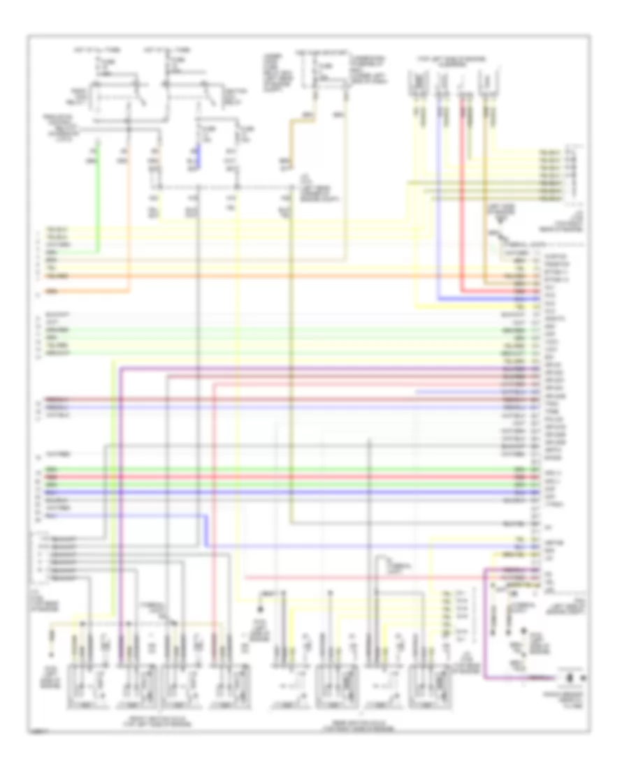
1.8L, Engine Controls Wiring Diagram, GX (4 of 5) for Honda Civic LX 2010
List of elements for 1.8L, Engine Controls Wiring Diagram, GX (4 of 5) for Honda Civic LX 2010:
- (behind right kick panel) injector control module
- (front left side of floor) g601
- (on transmission housing)
- (under left side of dash) injector control module relay
- 2nd clutch transmission fluid pressure switch (on transmission housing)
- 3rd clutch transmission fluid pressure switch (on transmission housing)
- 5v stabilize circuit/controller area network controller
- A/t clutch pressure control solenoid valve a
- A/t clutch pressure control solenoid valve b
- A/t clutch pressure control solenoid valve c (on transmission housing)
- A/t gear position dimming circuit
- A/t gear position indicator drive circuit
- Compulsory turninf-off circuit
- Computer data lines system
- F-can transceiver
- Fail-safe circuit
- Fuel pressure regulator leak check connector (front of engine compt)
- Fuel pressure regulator shut-off solenoid valve (right rear of engine)
- Fuel pressure regulator switch (right rear of engine)
- Fuel tank internal solenoid valve (left side of trunk)
- G101 (right rear of engine)
- G401 (behind left kick panel)
- G504 (near under-dash junction box)
- Gauge control module (tach)
- Inj1
- Inj2
- Inj3
- Inj4
- Injcntl1
- Injcntl2
- Injcntl3
- Injcntl4
- Injigp
- Injmode
- Lg1
- Lg2
- Mil ind
- Pg1
- Pg3
- Pnk
- Red
- S2 (thermal joint)
- Shift control solenoid valve a
- Shift control solenoid valve b
- Shift control solenoid valve c
- Shift control solenoid valve d
- Warning drive circuit
1.8L, Engine Controls Wiring Diagram, GX (5 of 5) for Honda Civic LX 2010
List of elements for 1.8L, Engine Controls Wiring Diagram, GX (5 of 5) for Honda Civic LX 2010:
- (on throttle body) tp sensor/throttle actuator
- (rear of engine) map sensor
- (right rear of engine) g101
- (thermal joint)
- (top rear of engine) j/c c105
- (top right front of engine) eop sensor
- Afs+
- Afs-
- Afshtc
- Ckp
- Ckp sensor (top left rear of engine)
- Cmp
- Cmp sensor (rear of engine)
- Etcsm+
- Etcsm-
- F24
- Fuse 10a
- Fuse 15a
- Fuse 7.5a
- G101 (right rear of engine)
- Hot in on or start
- Icm
- Ig1
- Ig1etcs
- Ignition coils (top of engine)
- Igpls1
- Igpls2
- Igpls3
- Igpls4
- Inj1
- Inj2
- Inj3
- Inj4
- Injectors (top of engine, at 1, 2, 3 & 4 cylinders)
- J/c c105 (top rear of engine)
- K14
- Lg1
- Lg2
- Map
- Micu
- Pcm (left side of engine compt)
- Pf2
- Pgm etcs
- Pnk
- Poil
- Red
- S1 (thermal joint)
- S3 (thermal joint)
- S5 (thermal joint)
- Sg1
- Sg3
- Sho2s
- Tpsa
- Tpsb
- Under- dash fuse/ relay box (under left end of dash)
- Under-dash junction box (under left j14 side of dash)
- Vcc1
- Vcc3
2.0L
2.0L, Engine Controls Wiring Diagram (1 of 3) for Honda Civic LX 2010
List of elements for 2.0L, Engine Controls Wiring Diagram (1 of 3) for Honda Civic LX 2010:
- (behind left kick panel) g401
- (near under-dash junction box) g504
- (under left side of dash) under-dash junction box
- 100a
- 2 door
- Acc
- Acpd
- Air conditioning system
- App sensor (under left side of dash)
- Aps2
- Apsa
- Bksw
- Bkswnc
- Can h
- Can l
- Clutch pedal position switch (under left side of dash)
- Computer data lines system
- Controller area network controller 5v stabilize circuit/
- Cooling fans system
- Crmtcls
- Cruise control system
- Ecm (left side of engine compt)
- Ect2
- Eld
- Eld unit
- Etcs control relay
- Etcsrly
- Evap canister purge valve (right rear of engine)
- Evap canister vent shut valve (under left side of floor)
- F16
- F19
- Fanh
- Fanl
- Fast controller area network transceiver
- Ftp
- Ftp sensor
- Fuse 15a
- Fuse 7.5a
- G301 (lower left side of engine compt)
- Gauge control module (tach)
- Hot at all times
- Hot in on or start
- Ig1
- Ignition coil relay
- Igp
- Imofpr
- J14
- K14
- Maf/iat sensor (left side of engine compt)
- Micu
- Mil ind
- Mrly
- Multi- fuse 1
- Navigation system
- Oil pressure switch (near oil filter)
- Pgm-fi main relay 1
- Pgm-fi sub- relay
- Pnk
- Power distribution system
- Power window master switch (if equipped)
- Red
- Rvslck
- S-net5v
- Scs
- Sg4
- Sg5
- Sg6
- Shift interlock system
- Sub rly
- Under-dash fuse/relay box (under left end of dash)
- Under-hood fuse/relay box (left side of engine compt)
- Vcc4
- Vcc5
- Vcc6
- Vssout
- Vsv
- Warning drive circuit
- Wen
2.0L, Engine Controls Wiring Diagram (2 of 3) for Honda Civic LX 2010
List of elements for 2.0L, Engine Controls Wiring Diagram (2 of 3) for Honda Civic LX 2010:
- (front of engine) vtc oil control solenoid valve
- (in top of fuel tank)
- (rear of engine compt) a/f sensor connector
- (right rear of engine) ect sensor 1
- (top rear of engine) j/c c105
- (under transmission housing) output shaft (countershaft) speed sensor
- A14
- A15
- A16
- A17
- A18
- A19
- A21
- A22
- A23
- Altc
- Altf
- Altl
- B10
- B14
- B15
- B16
- B17
- B18
- B20
- B21
- B22
- B23
- Barometer sensor
- Brake pedal position switch (under left side of dash)
- Ecm (left side of engine compt)
- Ect sensor 2 (lower left side of radiator)
- Ect1
- Eps control unit (if equipped) (behind right kick panel)
- F10
- F11
- F25
- F30
- F31
- Floor) g601
- Fuel pump
- Fuse 15a
- G101 (left rear of engine)
- G16
- Hot in on or start
- Iat
- J/c c101 (near brake master cylinder)
- J/c c105 (top rear of engine)
- J/c c207 (right rear of engine compt)
- Micu
- Opsw
- Pcs
- Pg1
- Pg2
- Pgm-fi main relay 2
- Pnk
- Red
- Rocker arm oil control solenoid (top front of engine)
- S-net
- S1 (terminal joint)
- Scs
- Secondary ho2s connector (under center console)
- Sg2
- So2shtc
- Starting/ charging system
- Under-dash fuse/relay box (under left end of dash)
- Vcc2
- Vg+
- Vg-
- Vts
2.0L, Engine Controls Wiring Diagram (3 of 3) for Honda Civic LX 2010
List of elements for 2.0L, Engine Controls Wiring Diagram (3 of 3) for Honda Civic LX 2010:
- (left rear of engine) g101
- (left rear side of engine) map sensor
- (on throttle body) tp sensor/throttle actuator
- (thermal joint) s1
- (top front of engine) rocker arm oil pressure switch
- (top left side of engine, at 1, 2, 3 & 4 cylinders) injectors
- (top rear of engine)
- (top rear of engine) j/c c105
- Afs+
- Afs-
- Afshtc
- Ckp
- Ckp sensor (lower front of engine)
- Cmp a
- Cmp b
- Cmp sensor a (right rear of engine)
- Cmp sensor b (right rear of engine)
- E27
- Ecm (left side of engine compt)
- Etcsm+
- Etcsm-
- F24
- Fuse 10a
- Fuse 15a
- G101 (left rear of engine)
- Hot in on or start
- Icm
- Ig1
- Ig1etcs
- Ignition coils (top of engine)
- Igpls1
- Igpls2
- Igpls3
- Igpls4
- Inj1
- Inj2
- Inj3
- Inj4
- J/c c101 (near brake master cylinder)
- J/c c105
- Knock sensor (left front side of engine)
- Lg1
- Lg2
- Map
- Pgm etcs
- Red
- S2 (thermal joint)
- Sg1
- Sg3
- Sho2s
- Tpsa
- Tpsb
- Under- dash fuse/ relay box (under left end of dash)
- Vcc1
- Vcc3
- Vtc
- Vtpsw

 Čeština
 Dansk
Dansk Deutsch
 Ελληνικά
 English
 English
 Español
 Suomi
Suomi Français
 Français
 Hrvatski
 Magyar
 Italiano
 日本語
日本語 한국어
한국어 Nederlands
 Polski
 Português
 Português
 Română
 Русский
 Slovenčina
 Slovenščina
 Svenska
 Türkçe
 中文 (中国)