
 Čeština
 Dansk
Dansk Deutsch
 Ελληνικά
 English
 English
 Español
 Suomi
Suomi Français
 Français
 Hrvatski
 Magyar
 Italiano
 日本語
日本語 한국어
한국어 Nederlands
 Polski
 Português
 Português
 Română
 Русский
 Slovenčina
 Slovenščina
 Svenska
 Türkçe
 中文 (中国)

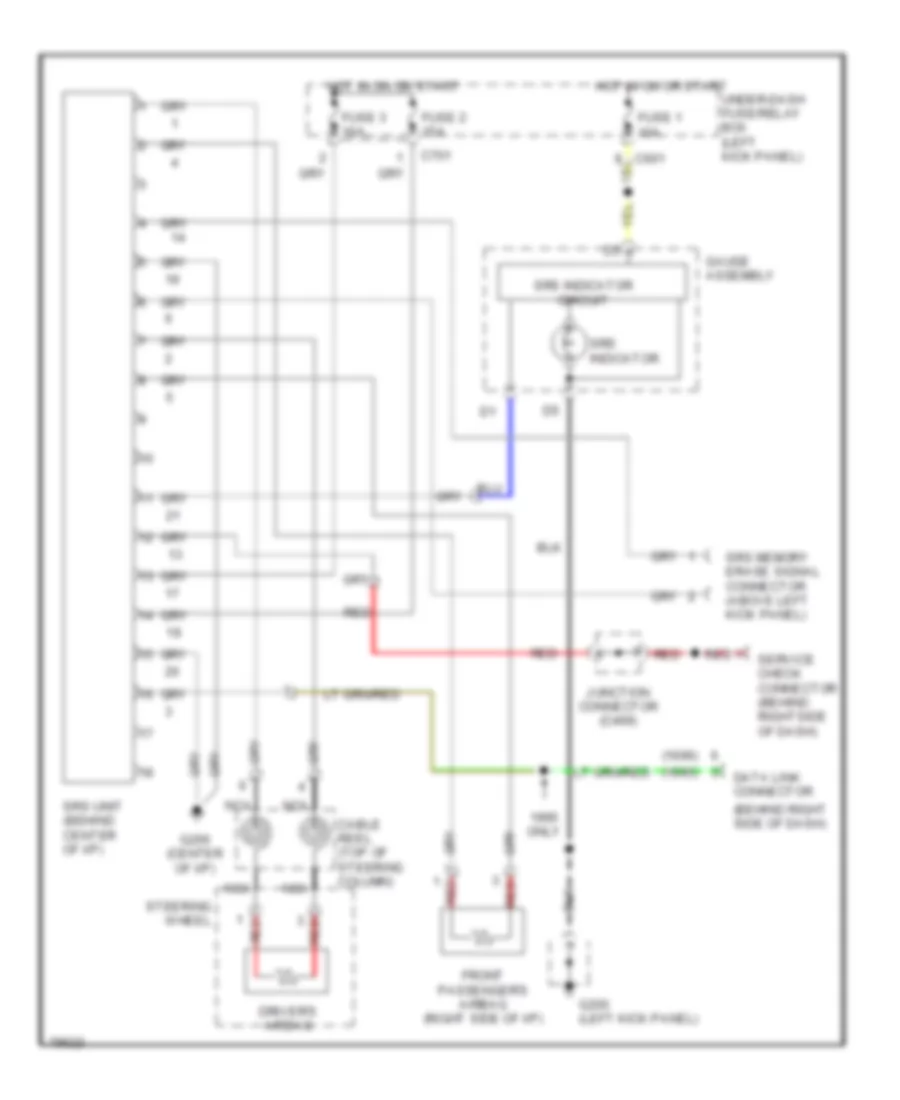
SUPPLEMENTAL RESTRAINTS
Supplemental Restraint Wiring Diagram for Honda Odyssey LX 1995
List of elements for Supplemental Restraint Wiring Diagram for Honda Odyssey LX 1995:

ANTI-LOCK BRAKESCOMPUTER DATA LINESDEFOGGERSAIR CONDITIONINGANTI-THEFTEXTERIOR LIGHTSCOOLING FANENGINE PERFORMANCECRUISE CONTROLGROUND DISTRIBUTIONHEADLIGHTSINTERIOR LIGHTSPOWER DOOR LOCKSINSTRUMENT CLUSTERHORNPOWER DISTRIBUTIONPOWER SEATSPOWER TOP/SUNROOFSTARTING/CHARGINGPOWER MIRRORSSHIFT INTERLOCKSRADIOPOWER WINDOWSWARNING SYSTEMSSUPPLEMENTAL RESTRAINTSTRANSMISSIONWIPER/WASHER