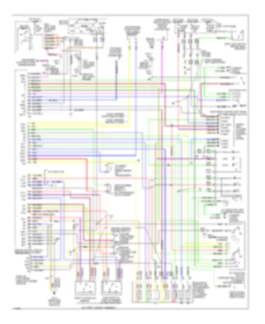
Electronic controlled transmission solenoid (in trans. valve body assembly)
Engine control module (behind right of dash)
Engine coolant temperature sensor (left front side of eng compt)
Eo1
Eo2
G100
G112 (rear side of intake manifold)
Gauge fuse 15a
Hot at all times
Hot in on or start
I123
I125
I128
I129
I130
I134
I54
I65
I68
I72
I75
I78
I79
I80
I83
I87
I92
I93
I94
Idl1
Idl2
Ig2
Igf
Igniter (right rear corner of engine compt)
Ignition switch
Igsw
Igt
Instru- ment cluster system (combina- tion meter)
Instrument cluster system (speedometer)
Interior lights system
J/b 1 (left kick panel)
J/b 3 (behind center of dash)
J/b 3 (center of dash)
J/c 1 (left side of engine compt.)
J/c 6 (behind center of dash)
J/c 7 (behind center b
L indic
Mass air flow meter (near air cleaner housing)
Mrel
N indic
Nc2+
Nc2-
Nco+
Nco-
Norm
Nsw
O/d direct clutch speed sensor (on transmission)
O/d indic
O/d main switch
Od1
Od2
Of dash)
Off
P indic
Pwr
R indic
R n
R/b 2 (left side of engine compt.)
Red
S indic
Sln-
Slt+
Slt-
Slu-
Sp1
Sp2+
Sp2-
St2
Sta
Start
Starting/ charging
Stop fuse 20a
Stop light switch (brake pedal bracket)
Stp
Sub-throttle position sensor (w/traction ctrl.)
Te1
Th0
Tha
Throttle position sensor
Thw
Traction ecu (behind right side of dash)
Vcc
Vehicle speed sensor 2 (for e.c.t.) (on transmission output shaft)
Vg-
Vta1
Vta2
W/ trac ctrl
W/o trac ctrl
We use cookies on our website to give you the most relevant experience by remembering your preferences and repeat visits. By clicking “Accept All”, you consent to the use of ALL the cookies. However, you may visit "Cookie Settings" to provide a controlled consent.
This website uses cookies to improve your experience while you navigate through the website. Out of these, the cookies that are categorized as necessary are stored on your browser as they are essential for the working of basic functionalities of the website. We also use third-party cookies that help us analyze and understand how you use this website. These cookies will be stored in your browser only with your consent. You also have the option to opt-out of these cookies. But opting out of some of these cookies may affect your browsing experience.
Necessary cookies are absolutely essential for the website to function properly. This category only includes cookies that ensures basic functionalities and security features of the website. These cookies do not store any personal information.
Any cookies that may not be particularly necessary for the website to function and is used specifically to collect user personal data via analytics, ads, other embedded contents are termed as non-necessary cookies. It is mandatory to procure user consent prior to running these cookies on your website.
 Čeština
 Dansk
Dansk Deutsch
 Ελληνικά
 English
 English
 Español
 Suomi
Suomi Français
 Français
 Hrvatski
 Magyar
 Italiano
 日本語
日本語 한국어
한국어 Nederlands
 Polski
 Português
 Português
 Română
 Русский
 Slovenčina
 Slovenščina
 Svenska
 Türkçe
 中文 (中国)
 עברית
עברית