AIR CONDITIONING
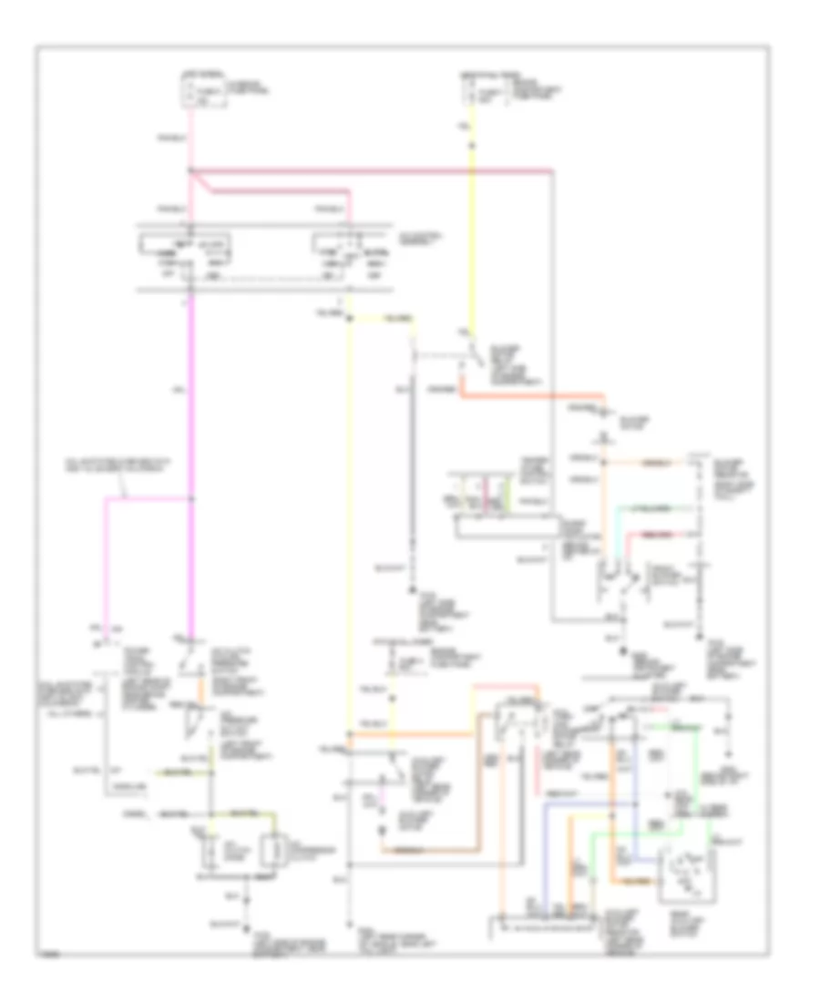
4.9L
4.9L, A/C Wiring Diagram for Ford Cutaway E350 1996


List of elements for 4.9L, A/C Wiring Diagram for Ford Cutaway E350 1996:
- (behind instrument cluster)
- (behind right side of i/p)
- (left front of engine compartment)
- (left rear corner of vehicle)
- (left rear of engine compartment near brake master cylinder)
- (left side of engine compartment near battery)
- (left side of engine compartment, near battery)
- (right front of engine compartment)
- (right side of safety wall)
- 15a
- A/c pressure cut out switch
- A/c clutch cycling pressure switch
- A/c clutch diode
- A/c compressor clutch
- A/c control assembly
- Aux- iliary high blower motor relay
- Auxiliary blower motor
- Auxiliary blower motor relay (left rear corner of vehicle)
- Auxiliary blower motor resistor (left rear corner of vehicle)
- Auxiliary blower switch
- Blend door actuator (behind center of i/p)
- Blower motor
- Blower motor relay (left side of engine compartment)
- Blower motor resistor
- Def
- Engine compartment fuse panel
- Floor
- Front blower switch
- Fuse 9
- Fuse a 60a
- Fuse f 60a
- G108
- G108 (left side of engine compartment near battery)
- G202
- G206
- G404 (left rear corner of vehicle, near left tail light)
- Hot at all times
- Hot in run
- Interior fuse panel
- Lo/ rear
- Max
- Mix
- Norm
- Off
- Pcm power relay
- Power- train control module
- Rear auxiliary blower switch
- Red
- Temper- ature control switch
- Vent
- W/ rear control
- W/o rear con- trol
- Wide open throttle relay (lower left side of engine compartment)
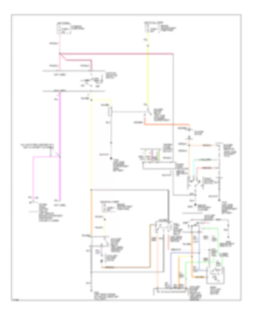
Heater Wiring Diagram for Ford Cutaway E350 1996
List of elements for Heater Wiring Diagram for Ford Cutaway E350 1996:
- (behind instrument cluster)
- (behind right side of i/p)
- (left rear corner of vehicle)
- (not used)
- (right side of safety wall)
- 15a
- 5.8l 49 states over 8600 gvw and 7.5l except california
- Aux- iliary high blower motor relay
- Auxiliary blower motor
- Auxiliary blower motor relay (left rear corner of vehicle)
- Auxiliary blower motor resistor (left rear corner of vehicle)
- Auxiliary blower switch
- Blend door actuator (behind center of i/p)
- Blower motor
- Blower motor relay (left side of engine compartment)
- Blower motor resistor
- Def
- Engine compartment fuse panel
- Floor
- Front blower switch
- Function selector switch
- Fuse 9
- Fuse a 60a
- Fuse f 60a
- G108 (left side of engine compartment near battery)
- G202
- G206
- G404 (left rear corner of vehicle, near left tail light)
- Hot at all times
- Hot in run
- Interior fuse panel
- Mix
- Off
- Power- train control module (left rear of engine compartment near brake master cylinder)
- Rear auxiliary blower switch
- Temper- ature control switch
- Vent
- W/ rear control
- W/o rear con- trol
5.8L
5.8L, A/C Wiring Diagram for Ford Cutaway E350 1996
List of elements for 5.8L, A/C Wiring Diagram for Ford Cutaway E350 1996:
- (5.8l 49 states over 8600 gvw and 7.5l exc. california)
- (all others)
- (behind right side of i/p)
- (left front of engine compartment)
- (left rear corner of vehicle)
- (left rear of engine compt near brake master cylinder)
- (right front of engine compartment)
- (right side of safety wall)
- 15a
- 5.8l 49 states over 8600 gvw and 7.5l except california
- A/c pressure cut out switch
- A/c clutch cycling pressure switch
- A/c clutch diode
- A/c compressor clutch
- A/c control assembly
- Aux- iliary high blower motor relay
- Auxiliary blower motor
- Auxiliary blower motor relay (left rear corner of vehicle)
- Auxiliary blower motor resistor (left rear corner of vehicle)
- Auxiliary blower switch
- Blend door actuator (behind center of i/p)
- Blower motor
- Blower motor relay (left side of engine compartment)
- Blower motor resistor
- Def
- Diesel
- Engine compartment fuse panel
- Floor
- Front blower switch
- Fuse 9
- Fuse a 60a
- Fuse f 60a
- G108 (left side of engine compartment near battery)
- G108 (left side of engine compartment, near battery)
- G202
- G206 (behind instrument cluster)
- G404 (left rear corner of vehicle, near left tail light)
- Gasoline
- Hot at all times
- Hot in run
- Interior fuse panel
- Lo/ rear
- Max
- Mix
- Norm
- Off
- Power- train control module
- Rear auxiliary blower switch
- Temper- ature control switch
- Vent
- W/ rear control
- W/o rear con- trol
Heater Wiring Diagram for Ford Cutaway E350 1996
List of elements for Heater Wiring Diagram for Ford Cutaway E350 1996:
- (behind instrument cluster)
- (behind right side of i/p)
- (left rear corner of vehicle)
- (not used)
- (right side of safety wall)
- 15a
- 5.8l 49 states over 8600 gvw and 7.5l except california
- Aux- iliary high blower motor relay
- Auxiliary blower motor
- Auxiliary blower motor relay (left rear corner of vehicle)
- Auxiliary blower motor resistor (left rear corner of vehicle)
- Auxiliary blower switch
- Blend door actuator (behind center of i/p)
- Blower motor
- Blower motor relay (left side of engine compartment)
- Blower motor resistor
- Def
- Engine compartment fuse panel
- Floor
- Front blower switch
- Function selector switch
- Fuse 9
- Fuse a 60a
- Fuse f 60a
- G108 (left side of engine compartment near battery)
- G202
- G206
- G404 (left rear corner of vehicle, near left tail light)
- Hot at all times
- Hot in run
- Interior fuse panel
- Mix
- Off
- Power- train control module (left rear of engine compartment near brake master cylinder)
- Rear auxiliary blower switch
- Temper- ature control switch
- Vent
- W/ rear control
- W/o rear con- trol
7.3L
7.3L DI Turbo Diesel, A/C Wiring Diagram for Ford Cutaway E350 1996
List of elements for 7.3L DI Turbo Diesel, A/C Wiring Diagram for Ford Cutaway E350 1996:
- (5.8l 49 states over 8600 gvw and 7.5l exc. california)
- (all others)
- (behind right side of i/p)
- (left front of engine compartment)
- (left rear corner of vehicle)
- (left rear of engine compt near brake master cylinder)
- (right front of engine compartment)
- (right side of safety wall)
- 15a
- 5.8l 49 states over 8600 gvw and 7.5l except california
- A/c pressure cut out switch
- A/c clutch cycling pressure switch
- A/c clutch diode
- A/c compressor clutch
- A/c control assembly
- Aux- iliary high blower motor relay
- Auxiliary blower motor
- Auxiliary blower motor relay (left rear corner of vehicle)
- Auxiliary blower motor resistor (left rear corner of vehicle)
- Auxiliary blower switch
- Blend door actuator (behind center of i/p)
- Blower motor
- Blower motor relay (left side of engine compartment)
- Blower motor resistor
- Def
- Diesel
- Engine compartment fuse panel
- Floor
- Front blower switch
- Fuse 9
- Fuse a 60a
- Fuse f 60a
- G108 (left side of engine compartment near battery)
- G108 (left side of engine compartment, near battery)
- G202
- G206 (behind instrument cluster)
- G404 (left rear corner of vehicle, near left tail light)
- Gasoline
- Hot at all times
- Hot in run
- Interior fuse panel
- Lo/ rear
- Max
- Mix
- Norm
- Off
- Power- train control module
- Rear auxiliary blower switch
- Temper- ature control switch
- Vent
- W/ rear control
- W/o rear con- trol
Heater Wiring Diagram for Ford Cutaway E350 1996
List of elements for Heater Wiring Diagram for Ford Cutaway E350 1996:
- (behind instrument cluster)
- (behind right side of i/p)
- (left rear corner of vehicle)
- (not used)
- (right side of safety wall)
- 15a
- 5.8l 49 states over 8600 gvw and 7.5l except california
- Aux- iliary high blower motor relay
- Auxiliary blower motor
- Auxiliary blower motor relay (left rear corner of vehicle)
- Auxiliary blower motor resistor (left rear corner of vehicle)
- Auxiliary blower switch
- Blend door actuator (behind center of i/p)
- Blower motor
- Blower motor relay (left side of engine compartment)
- Blower motor resistor
- Def
- Engine compartment fuse panel
- Floor
- Front blower switch
- Function selector switch
- Fuse 9
- Fuse a 60a
- Fuse f 60a
- G108 (left side of engine compartment near battery)
- G202
- G206
- G404 (left rear corner of vehicle, near left tail light)
- Hot at all times
- Hot in run
- Interior fuse panel
- Mix
- Off
- Power- train control module (left rear of engine compartment near brake master cylinder)
- Rear auxiliary blower switch
- Temper- ature control switch
- Vent
- W/ rear control
- W/o rear con- trol
7.5L
7.5L, A/C Wiring Diagram for Ford Cutaway E350 1996
List of elements for 7.5L, A/C Wiring Diagram for Ford Cutaway E350 1996:
- (5.8l 49 states over 8600 gvw and 7.5l exc. california)
- (all others)
- (behind right side of i/p)
- (left front of engine compartment)
- (left rear corner of vehicle)
- (left rear of engine compt near brake master cylinder)
- (right front of engine compartment)
- (right side of safety wall)
- 15a
- 5.8l 49 states over 8600 gvw and 7.5l except california
- A/c pressure cut out switch
- A/c clutch cycling pressure switch
- A/c clutch diode
- A/c compressor clutch
- A/c control assembly
- Aux- iliary high blower motor relay
- Auxiliary blower motor
- Auxiliary blower motor relay (left rear corner of vehicle)
- Auxiliary blower motor resistor (left rear corner of vehicle)
- Auxiliary blower switch
- Blend door actuator (behind center of i/p)
- Blower motor
- Blower motor relay (left side of engine compartment)
- Blower motor resistor
- Def
- Diesel
- Engine compartment fuse panel
- Floor
- Front blower switch
- Fuse 9
- Fuse a 60a
- Fuse f 60a
- G108 (left side of engine compartment near battery)
- G108 (left side of engine compartment, near battery)
- G202
- G206 (behind instrument cluster)
- G404 (left rear corner of vehicle, near left tail light)
- Gasoline
- Hot at all times
- Hot in run
- Interior fuse panel
- Lo/ rear
- Max
- Mix
- Norm
- Off
- Power- train control module
- Rear auxiliary blower switch
- Temper- ature control switch
- Vent
- W/ rear control
- W/o rear con- trol
Heater Wiring Diagram for Ford Cutaway E350 1996
List of elements for Heater Wiring Diagram for Ford Cutaway E350 1996:
- (behind instrument cluster)
- (behind right side of i/p)
- (left rear corner of vehicle)
- (not used)
- (right side of safety wall)
- 15a
- 5.8l 49 states over 8600 gvw and 7.5l except california
- Aux- iliary high blower motor relay
- Auxiliary blower motor
- Auxiliary blower motor relay (left rear corner of vehicle)
- Auxiliary blower motor resistor (left rear corner of vehicle)
- Auxiliary blower switch
- Blend door actuator (behind center of i/p)
- Blower motor
- Blower motor relay (left side of engine compartment)
- Blower motor resistor
- Def
- Engine compartment fuse panel
- Floor
- Front blower switch
- Function selector switch
- Fuse 9
- Fuse a 60a
- Fuse f 60a
- G108 (left side of engine compartment near battery)
- G202
- G206
- G404 (left rear corner of vehicle, near left tail light)
- Hot at all times
- Hot in run
- Interior fuse panel
- Mix
- Off
- Power- train control module (left rear of engine compartment near brake master cylinder)
- Rear auxiliary blower switch
- Temper- ature control switch
- Vent
- W/ rear control
- W/o rear con- trol

 Čeština
 Dansk
Dansk Deutsch
 Ελληνικά
 English
 English
 Español
 Suomi
Suomi Français
 Français
 Hrvatski
 Magyar
 Italiano
 日本語
日本語 한국어
한국어 Nederlands
 Polski
 Português
 Português
 Română
 Русский
 Slovenčina
 Slovenščina
 Svenska
 Türkçe
 中文 (中国)