ANTI-LOCK BRAKES
Anti-lock Brake Wiring Diagrams for Ford Explorer 1996
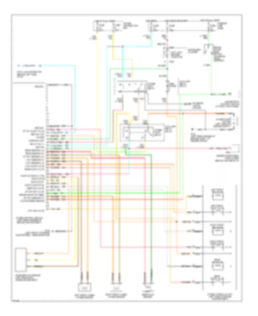
List of elements for Anti-lock Brake Wiring Diagrams for Ford Explorer 1996:
- 4wabs control module (left rear corner of engine compartment)
- 4wabs hydraulic unit (left side of engine compartment)
- 4wabs main relay
- 4wabs pump motor (left side of engine compt)
- 4wabs pump relay
- 87a
- Abs diode
- Acceleration sensor (left frame rail, under driver seat)
- Anti-lock brakes indicator
- Auxiliary relay box #1
- Brake on/off (boo) switch (on brake pedal support)
- Brake on/off sw feed
- C282
- C287
- C288
- Data link connector (behind left side of i/p)
- Exterior lights system
- Fuse 10a
- Fuse 15a
- Fuse 30a
- Fuse 7.5a
- G-switch #1
- G-switch status
- G104 (left rear corner of engine compt, at fender apron)
- G108 (left front of engine compartment, near radiator)
- Gem iso link
- Generic electronic module (gem) (behind center of i/p)
- Ground
- Hot at all times
- Hot in run
- Hot in run or start
- Ignition
- Instrument cluster
- Interior fuse panel
- L fnt dump valve
- L fnt iso valve
- L fnt sensor (hi)
- L fnt sensor (lo)
- Left front dump valve
- Left front iso valve
- Left front wheel 4wabs sensor
- Motor speed sens #2
- Nca
- Pnk
- Power
- Power distribution box
- Powertrain control module (at right kick panel)
- Pump motor rly ctrl g-switch #2
- Rear axle sensor
- Rear dump valve
- Rear iso valve
- Rear sensor (hi)
- Rear sensor (lo)
- Red/pnk
- Relay coil (-)
- Right front dump valve
- Right front iso valve
- Right front wheel 4wabs sensor
- Rt fnt dump valve
- Rt fnt iso valve
- Rt fnt sensor (hi)
- Rt fnt sensor (lo)
- Tan
- Tan/ red
- Tan/red
- Warning lamp
 Čeština
 Dansk
Dansk Deutsch
 Ελληνικά
 English
 English
 Español
 Suomi
Suomi Français
 Français
 Hrvatski
 Magyar
 Italiano
 日本語
日本語 한국어
한국어 Nederlands
 Polski
 Português
 Português
 Română
 Русский
 Slovenčina
 Slovenščina
 Svenska
 Türkçe
 中文 (中国)
 עברית
עברית