ANTI-LOCK BRAKES
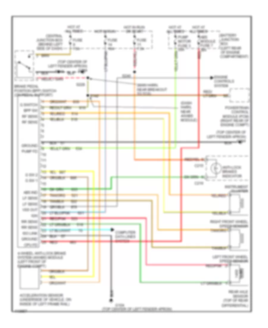
All-Wheel ABS Wiring Diagram for Ford Ranger 1999
 https://portal-diagnostov.com/license.html
Automotive Electricians Portal FZCO
Automotive Electricians Portal FZCO
https://portal-diagnostov.com/license.html
https://portal-diagnostov.com/license.html
Automotive Electricians Portal FZCO
Automotive Electricians Portal FZCO
List of elements for All-Wheel ABS Wiring Diagram for Ford Ranger 1999:
- (dash harn, near 4wabs module)
- (main harn, near breakout to tcs)
- (top center of left fender apron)
- (top center of left fender apron) g104
- 4-wheel anti-lock brake system (4wabs) module (left front of engine compt)
- Abs ind
- Abs module fuse 7 30a red
- Acceleration sensor (underside of vehicle, on inside of left frame rail)
- Anti-lock brakes indicator
- Battery junction box (left rear of engine compartment)
- Bpp sw
- Brake pedal position (bpp) switch (on pedal support)
- C215
- C216
- Central junction box (behind left side of dash)
- Computer data lines system
- Cpu fd
- Differential)
- Engine controls system
- Fuse 10a
- Fuse 7.5a
- G sw 1
- G sw 2
- G switch
- G104
- Ground
- Hot at all times
- Hot in run
- Hot in run or start
- Ign
- Instrument cluster
- Iso link
- Left front wheel speed sensor
- Lf sens
- Ohms
- Powertrain control module (pcm) (right rear of engine compt)
- Pump fd
- Pump motor fuse 3 50a
- Rear axle sensor (top of rear
- Red
- Red/pnk
- Rf sens
- Right front wheel speed sensor
- Rr sens
- S142
- S228
- S240
- Vss out
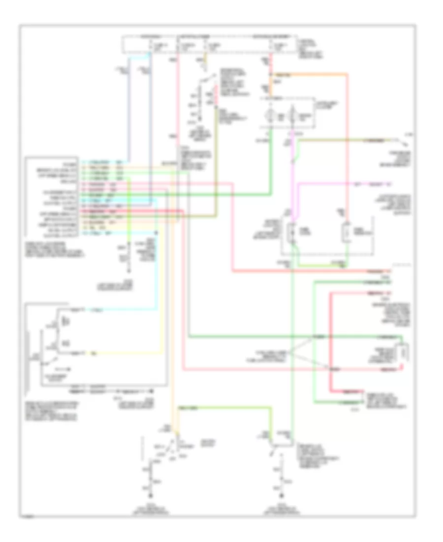
Rear Wheel ABS Wiring Diagram for Ford Ranger 1999
 https://portal-diagnostov.com/license.html
Automotive Electricians Portal FZCO
Automotive Electricians Portal FZCO
https://portal-diagnostov.com/license.html
https://portal-diagnostov.com/license.html
Automotive Electricians Portal FZCO
Automotive Electricians Portal FZCOList of elements for Rear Wheel ABS Wiring Diagram for Ford Ranger 1999:
- (main harn, near breakout to fuse junction panel)
- (top center of left fender apron)
- 1.2 ohms
- 22k ohms
- 4.0 ohms
- Abs ind
- Acc
- Battery junction box (left rear of engine compt)
- Bpp switch input
- Brake fluid level sw
- Brake fluid level switch (left rear of engine compartment, on brake fluid reservoir)
- Brake ind
- Brake pedal position (bpp) switch (behind left side of dash, on brake pedal support)
- C141
- C215
- C216
- C222
- C224
- C244
- Central junction box (behind left side of dash)
- Daytime running lamps (drl) module (left side of lower radiator
- Diff speed sens (hi)
- Diff speed sens (lo)
- Dump sol
- Dump sol output
- Fuse 11 7.5a
- Fuse 14 20a
- Fuse 30 10a
- Fuse 9 7.5a
- G104
- G104 (top center of left fender apron)
- G108 (left side of upper radiator support)
- Generic electronic module (gem)/ central timer module (ctm) (behind center of dash)
- Gnd
- Ground
- Hot at all times
- Hot in run
- Hot in run or start
- Ignition switch
- Instrument cluster
- Iso sol
- Iso sol output
- Keep alive pwr/rabs
- Lock
- Nca
- Off
- Park brake switch (on park brake assembly)
- Power
- Rabs data link test connector (on left rear of engine compartment)
- Rabs diagnostic test connector (c244) (behind right side of dash)
- Rabs diode
- Rabs ind ctrl
- Rabs resistor
- Rear anti-lock brake system (rabs) module (behind lower center of dash, right side of ashtray assembly)
- Rear anti-lock brake system (rabs) proportioning valve switch assembly (below left side of vehicle, on inside of left frame rail)
- Rear axle sensor (top of rear differential)
- Red
- Red/
- Red/pnk
- Run
- S118
- S143
- S204 (main harn, near breakout to rabs module)
- S205
- S228 (main harn, near breakout to tcs)
- S235
- S236
- S240
- S244
- Start
- Support)
- Valve reset input
- Valve reset switch

 Čeština
 Dansk
Dansk Deutsch
 Ελληνικά
 English
 English
 Español
 Suomi
Suomi Français
 Français
 Hrvatski
 Magyar
 Italiano
 日本語
日本語 한국어
한국어 Nederlands
 Polski
 Português
 Português
 Română
 Русский
 Slovenčina
 Slovenščina
 Svenska
 Türkçe
 中文 (中国)
