ENGINE PERFORMANCE
4.6L
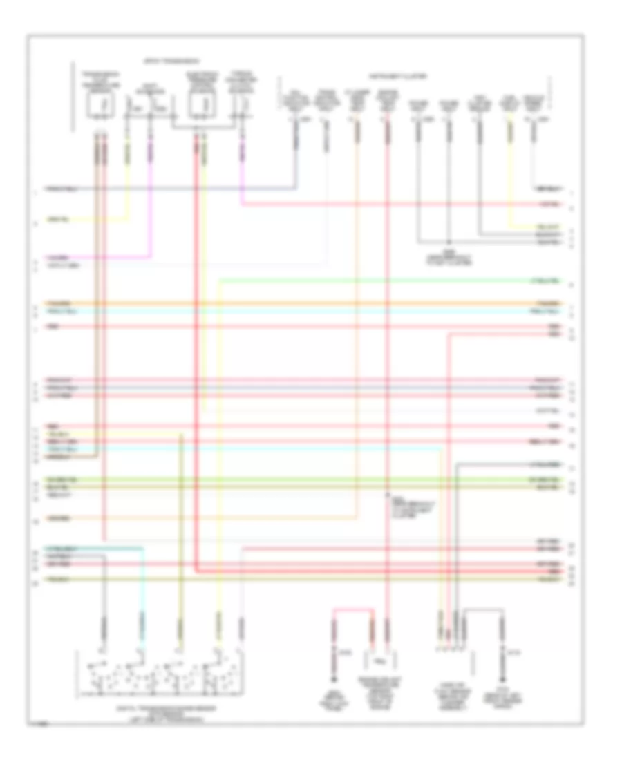
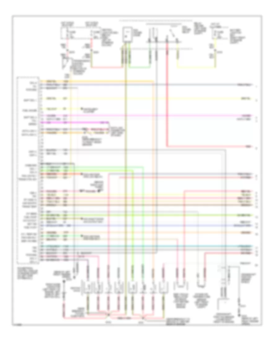
4.6L CNG, Engine Performance Wiring Diagrams (1 of 5) for Ford Crown Victoria 2000


List of elements for 4.6L CNG, Engine Performance Wiring Diagrams (1 of 5) for Ford Crown Victoria 2000:
- (behind right kick panel) g203
- (near breakout to front crash sensor)
- (near breakout to fuel injector 8)
- (near ground at center rear of engine)
- (rear of left front fender apron)
- A/c cycling
- Battery junction box (right front of engine compt)
- Case gnd
- Central junction box (below dash, left of steering column)
- Ckp (+)
- Ckp (-)
- Coil 1
- Coil 3
- Coil 4
- Coil 5
- Coil 6
- Cooling fans (fan high rly)
- Cooling fans (fan low relay)
- Crankshaft position sensor (lower right front of engine)
- Crankshaft position sensor shield
- Cyl temp ind
- Data link (+)
- Data link (-)
- Data link connector (left side of dash)
- Ect ind
- Egr vac reg
- Egr vacuum regulator solenoid (top center rear of engine)
- Eprom
- Fan high rly
- Fan low rly
- Fuel sol vlv
- Fuse 15a
- Fuse 25a
- Fuse 30a
- G104
- G104 (rear of left front fender apron)
- Hot at all times
- Hot in run or start
- Iat sens
- Ignition coils
- Intake air temperature sensor (left front of engine compt)
- Maf sig rtn
- Mil
- Nca
- Pcm power diode
- Pcm power relay
- Powertrain control module (behind left side of dash, on left side of firewall)
- Pwr gnd
- Radio noise capacitor (left front of engine, left side of left ignition coil)
- Red
- Relay center (left side of engine compt)
- Rt ho2s 12
- S100
- S101
- S103
- S119
- S134
- S135
- S151
- S223
- S276
- Shft sol 1
- Shft sol 2
- Tcil
- Tr1
- Tr2
- Tr4
- Trans ctrl sw
- Trans temp
- Transmission control switch (bottom of steering column)
- Vss (+)
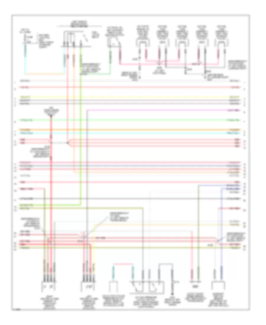
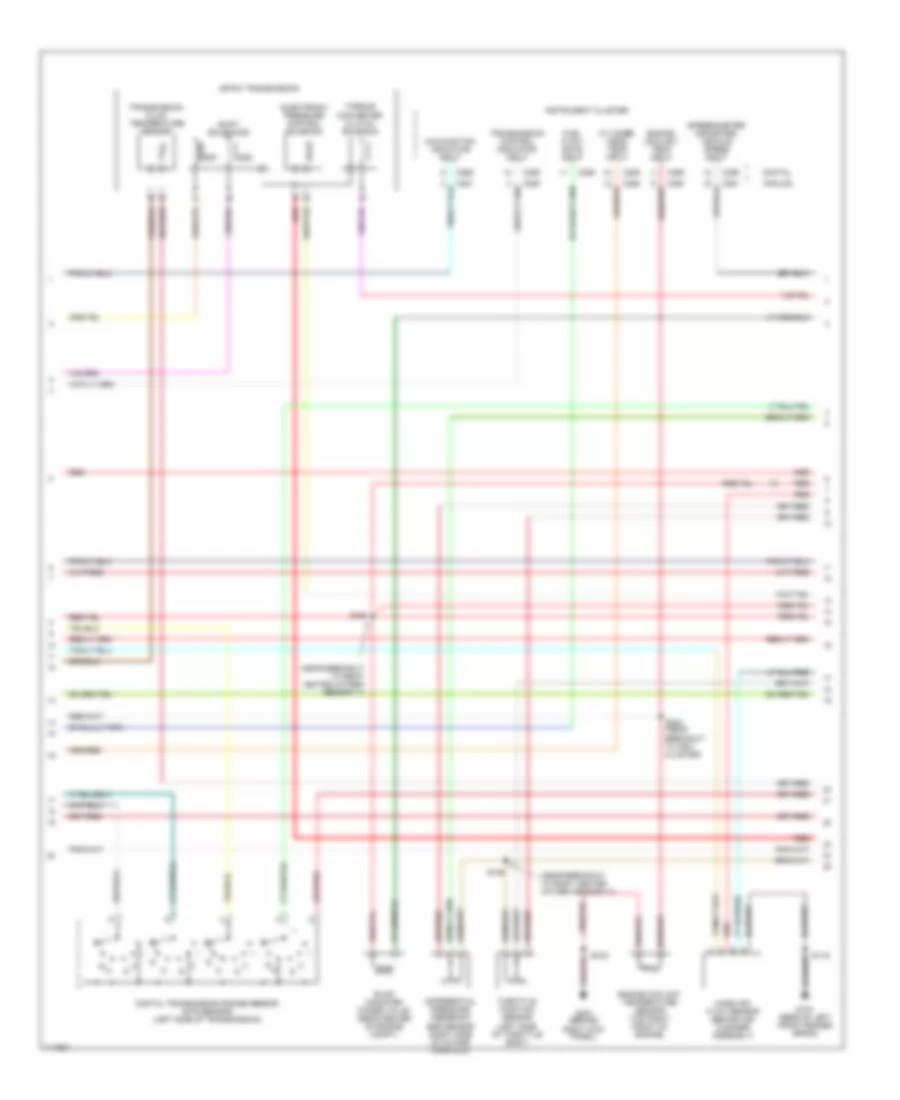
4.6L CNG, Engine Performance Wiring Diagrams (2 of 5) for Ford Crown Victoria 2000
List of elements for 4.6L CNG, Engine Performance Wiring Diagrams (2 of 5) for Ford Crown Victoria 2000:
- 4r70w transmission
- C250
- C251
- Cylinder head temp input
- Digital transmission range sensor (dtr sensor) (left side of transmission)
- Electronic pressure control solenoid
- Engine coolant temp input
- Engine coolant temperature sensor (top right front of engine)
- Fuel display input
- G104 (rear of left front fender apron)
- G203 (behind right kick panel)
- Inst cluster ground
- Instrument cluster
- Mal- function indicator input
- Mass air- flow sensor (behind air cleaner assembly)
- Power input
- R n
- Red
- S105
- S119
- S222 (near breakout to instrument cluster)
- S299 (near breakout to inst cluster)
- Shift solenoids
- Ss1
- Ss2
- Torque converter clutch solenoid
- Trans control indicator input
- Transmission fluid temperature sensor
- Vehicle speed input
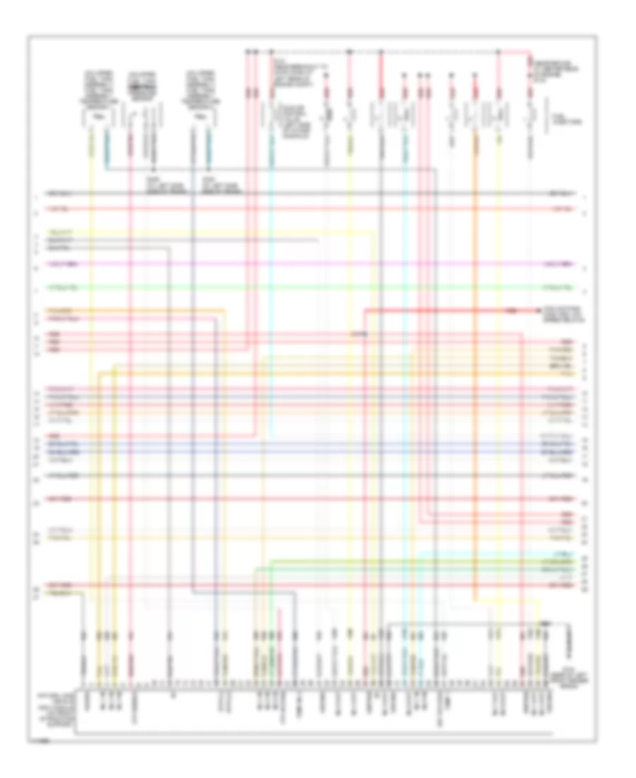
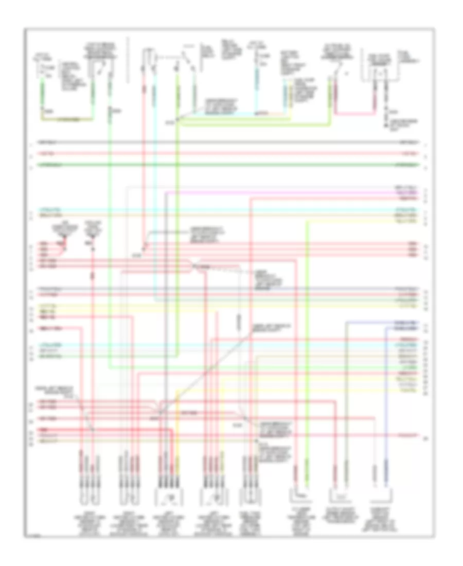
4.6L CNG, Engine Performance Wiring Diagrams (3 of 5) for Ford Crown Victoria 2000
List of elements for 4.6L CNG, Engine Performance Wiring Diagrams (3 of 5) for Ford Crown Victoria 2000:
- (at left kick panel)
- (center rear of luggage compt) g407
- (in trunk, on left support) inertia fuel shutoff switch
- (left side of engine compt) relay center
- (near breakout to 12-pin conn at left rear of engine compt)
- (near breakout to 12-pin conn at left rear of engine compt) s130
- (near breakout to 2-pin conn at left side of luggage compt)
- (near breakout to conn at left rear of transmission)
- (near breakout to conn at left rear of transmission) s148
- (on fuel tank assembly) fuel tank solenoid valve 1
- (on fuel tank assembly) fuel tank solenoid valve 2
- (on fuel tank assembly) fuel tank solenoid valve 3
- (on fuel tank assembly) fuel tank solenoid valve 4
- (on top of engine, on fuel rail) fuel rail cutoff solenoid
- (rear of left front fender apron) g104
- A/c clutch cycling pressure switch (right rear of engine compt, on a/c accumulator)
- A/c high pressure cutout switch (right side of engine compt, near battery junction box)
- Air conditioning (a/c cutout relay)
- Battery junction box (right front of engine compt)
- Camshaft position sensor (left front of engine, below left ignition coil)
- Fuel valve relay
- Fuse 20a
- G104 (rear of left front fender apron)
- Hot at all times
- Left heated oxygen sensor 22 (in exhaust, rear of catalyst)
- Nca
- Output shaft speed sensor (left rear side of transmission)
- Red
- Right heated oxygen sensor 12 (in exhaust, rear of catalyst)
- S119
- S125
- S129 (near breakout to 12-pin conn at left rear of engine compt)
- S147
- S156
- S298
- S427
4.6L CNG, Engine Performance Wiring Diagrams (4 of 5) for Ford Crown Victoria 2000
List of elements for 4.6L CNG, Engine Performance Wiring Diagrams (4 of 5) for Ford Crown Victoria 2000:
- (at left side side of trunk)
- (near ground at center rear of engine) s143
- (on upper fuel tank assembly) fuel tank assembly temperature sensor 1
- (on upper fuel tank assembly) fuel tank assembly temperature sensor 2
- (on upper fuel tank assembly) fuel tank pressure sensor
- Cooling fans (high and low speed relays)
- Data (+)
- Data (-)
- Ftp return
- Ftp sensor
- Fuel injectors
- G104 (rear of left front fender apron)
- Ground
- I/p
- Idle air control valve (left side of intake manifold)
- Ignition
- Inj 1 in
- Inj 1 out
- Inj 2 in
- Inj 2 out
- Inj 3 in
- Inj 3 out
- Inj 4 in
- Inj 4 out
- Inj 5 in
- Inj 5 out
- Inj 6 in
- Inj 6 out
- Inj 7 in
- Inj 7 out
- Inj 8 in
- Inj 8 out
- Natural gas vehicle (ngv) module (on front of radiator support)
- Power
- Red
- Red/pnk
- Ref voltage
- S131 (near breakout to 42-pin conn at left rear of engine compt)
- S141
- S197
- S429
- S430
- Tan
- Tan/red
- Temp 1
- Temp no.2
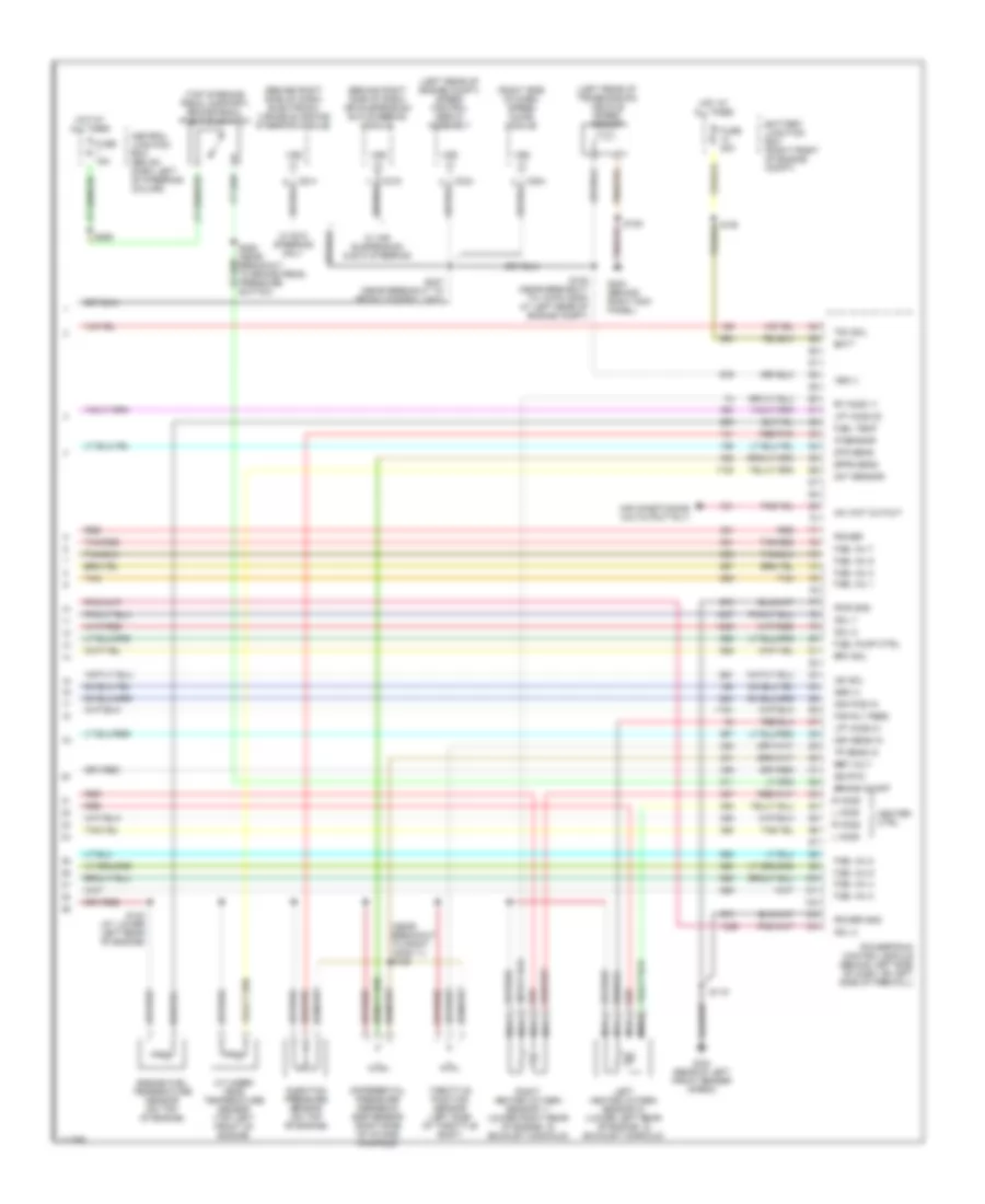
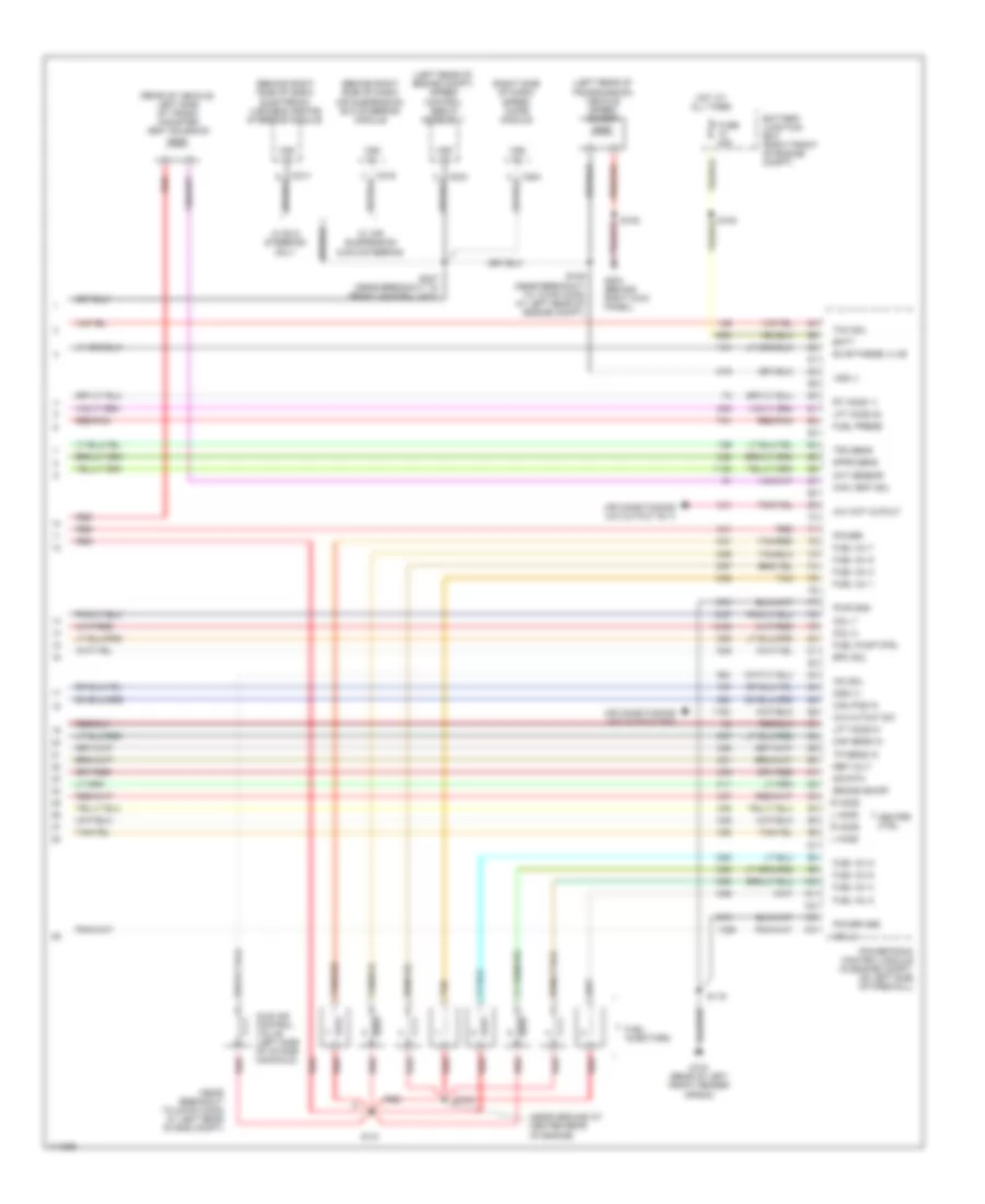
4.6L CNG, Engine Performance Wiring Diagrams (5 of 5) for Ford Crown Victoria 2000
List of elements for 4.6L CNG, Engine Performance Wiring Diagrams (5 of 5) for Ford Crown Victoria 2000:
- (behind right side of dash) air suspension/ evo steering module
- (behind right side of dash) electronic variable orifice steering module
- (left rear of engine compt) speed control servo assembly
- (left rear of transmission) vehicle speed sensor
- (near breakout to right h2os 11) s126
- (right side of dash) speed chime module
- (top of brake pedal support) brake pedal position switch
- A/c wot cutout
- Air conditioning (a/c cutout rly)
- Batt
- Battery junction box (right front of engine compt)
- Brake on/off
- C204
- C214
- C216
- C234
- Cam pos in
- Central junction box (below dash, left of steering column)
- Cht sensor
- Coil 2
- Coil 7
- Coil 8
- Cylinder head temperature sensor (top left front of engine)
- Differential pressure feedback egr sensor (right side of intake manifold)
- Dpfe sens
- Dtr sens
- Engine fuel temperature sensor (on top of engine)
- Epc sol
- Fan rly feed
- Fuel inj 1
- Fuel inj 2
- Fuel inj 3
- Fuel inj 4
- Fuel inj 5
- Fuel inj 6
- Fuel inj 7
- Fuel inj 8
- Fuel pump ctrl
- Fuel temp
- Fuse 15a
- Fuse 30a
- G104 (rear of left front fender apron)
- G203 (behind right kick panel)
- Heater ctrl
- Hot at all times
- Iac sol
- Injection pressure sensor (on top of engine)
- Ip sensor
- L ho2s
- Left heated oxygen sensor 21 (lower left rear of engine, in exhaust manifold)
- Lft ho2s 21
- Lft ho2s 22
- Maf sens in
- Nca
- Oss (+)
- Power
- Power gnd
- Powertrain control module (behind left side of dash, on left side of firewall)
- Pwr gnd
- R ho2s
- Red
- Red/pnk
- Ref volt
- Right heated oxygen sensor 11 (lower right rear of engine, in exhaust manifold)
- Rt ho2s 11
- S105
- S109 (near breakout to 12-pin conn at left rear of engine compt)
- S119
- S123 (at lower left rear of engine)
- S247 (near breakout to front control unit)
- S265
- Sig rtn
- Tan
- Tan/red
- Tcc sol
- Throttle position sensor (left side of throttle body)
- Tp sens in
- Vss (+)
- Vss (-)
- W/ air suspension & evo steering
- W/ evo steering only
4.6L, Engine Performance Wiring Diagrams (1 of 4) for Ford Crown Victoria 2000
List of elements for 4.6L, Engine Performance Wiring Diagrams (1 of 4) for Ford Crown Victoria 2000:
- (behind right kick panel) g203
- (near breakout to fuel injector 8)
- (near breakout to ground at center rear of engine)
- (rear of left front fender apron)
- A/c cutout
- Air conditioning (a/c cutout sw)
- Battery junction box (right front of engine compt)
- Case gnd
- Central junction box (below dash, left of steering column)
- Ckp (+)
- Ckp (-)
- Coil 1
- Coil 3
- Coil 4
- Coil 5
- Coil 6
- Cooling fans (fan high rly)
- Cooling fans (fan low relay)
- Crankshaft position sensor (lower right front of engine)
- Crankshaft position sensor shield
- Cyl temp ind
- Data link (+)
- Data link (-)
- Data link connector (left side of dash)
- Ect ind
- Egr vac reg
- Egr vacuum regulator solenoid (top center rear of engine)
- Eprom
- Fan high rly
- Fan low rly
- Fuel flow
- Fuel gauge
- Fuel pump
- Fuse 15a
- Fuse 25a
- Fuse 30a
- G104
- G104 (rear of left front fender apron)
- Hot at all times
- Hot in run or start
- Iat sens
- Ignition coils
- Instrument cluster
- Intake air temperature sensor (left front of engine compt)
- Maf sig rtn
- Mil
- Nca
- Pcm power diode
- Pcm power relay
- Powertrain control module (in engine compt, on left side of firewall)
- Pwr gnd
- Radio noise capacitor (left front of engine, left side of left ignition coil)
- Red
- Relay center (left side of engine compt)
- Rt ho2s 12
- S100
- S101
- S103
- S119
- S134
- S135 (near breakout to front crash sensor)
- S151
- S223
- S276
- Shft sol 1
- Shft sol 2
- Tcil
- Tr1
- Tr2
- Tr4
- Trans ctrl sw
- Trans temp
- Transmission control switch (bottom of steering column)
- Vss (-)
4.6L, Engine Performance Wiring Diagrams (2 of 4) for Ford Crown Victoria 2000
List of elements for 4.6L, Engine Performance Wiring Diagrams (2 of 4) for Ford Crown Victoria 2000:
- (near breakout to right heated oxygen sensor 11)
- (speedometer/ odometer) vehicle speed input
- 4r70w transmission
- Analog
- C250
- C251
- C255
- C256
- Cylinder head temp input
- Differential pressure feedback egr sensor (right side of intake manifold)
- Digital
- Digital transmission range sensor (dtr sensor) (left side of transmission)
- Electronic pressure control solenoid
- Engine coolant temp input
- Engine coolant temperature sensor (top right front of engine)
- Evap canister purge valve (rear center of engine compt)
- Fuel flow rate input
- G104 (rear of left front fender apron)
- G203 (behind right kick panel)
- Instrument cluster
- Malfunction indicator input
- Mass air- flow sensor (behind air cleaner assembly)
- R n
- Red
- S105
- S119
- S126
- S150
- S222 (near breakout to inst cluster)
- Shift solenoids
- Ss1
- Ss2
- Throttle position sensor (left side of throttle body)
- Torque converter clutch solenoid
- Transmission control indicator input
- Transmission fluid temperature sensor
4.6L, Engine Performance Wiring Diagrams (3 of 4) for Ford Crown Victoria 2000
List of elements for 4.6L, Engine Performance Wiring Diagrams (3 of 4) for Ford Crown Victoria 2000:
- (center rear of trunk) g407
- (in trunk, on left support) inertia fuel shutoff switch
- (near breakout to 12-pin conn at left rear of engine compt)
- (near breakout to 8-pin conn left rear of engine)
- (near left rear of engine compt)
- (near left rear of engine compt) s148
- (top of brake pedal support) brake pedal position switch
- Air conditioning (a/c cutout relay)
- Battery junction box (right front of engine compt)
- Camshaft position sensor (left front of engine, below left ignition coil)
- Central junction box) (below dash, left of steering column)
- Cooling fans (fan low relay)
- Cylinder head temperature sensor (top left front of engine)
- Fuel pump prime connector (left sdie of engine compt)
- Fuel pump relay
- Fuel pump/ fuel gauge sender
- Fuel tank assembly
- Fuel tank pressure sensor (on upper fuel tank assembly)
- Fuse 15a
- Fuse 20a
- Hot at all times
- Left heated oxygen sensor 21 (lower left rear of engine, in exhaust manifold)
- Left heated oxygen sensor 22 (in exhaust, rear of catalyst)
- Nca
- Output shaft speed sensor (left rear side of transmission)
- Red
- Red/pnk
- Relay center (left side of engine compt)
- Right heated oxygen sensor 11 (lower right rear of engine, in exhaust manifold)
- Right heated oxygen sensor 12 (in exhaust, rear of catalyst)
- S115 (near breakout to 16-pin conn at left rear of engine compt)
- S123
- S124
- S125
- S129
- S130
- S147
- S265
- S402
4.6L, Engine Performance Wiring Diagrams (4 of 4) for Ford Crown Victoria 2000
List of elements for 4.6L, Engine Performance Wiring Diagrams (4 of 4) for Ford Crown Victoria 2000:
- (behind right side of dash) air suspension/ evo steering module
- (behind right side of dash) electronic variable orifice steering module
- (left rear of engine compt) speed control servo assembly
- (left rear of transmission) vehicle speed sensor
- (near breakout to 42-pin conn at left rear of eng compt)
- (near ground at center rear of engine)
- (rear of vehicle, left side of trunk) canister vent solenoid
- (right side of dash) speed chime module
- A/c cutout sw
- A/c wot cutout
- Air conditioning (a/c cutout rly)
- Air conditioning (a/c cutout sw)
- Batt
- Battery junction box (right front of engine compt)
- Brake on/off
- C204
- C214
- C216
- C234
- Cam pos in
- Can vent sol
- Cht sensor
- Coil 2
- Coil 7
- Coil 8
- Dpfe sens
- Epc sol
- Evap purge vlve
- Fuel inj 1
- Fuel inj 2
- Fuel inj 3
- Fuel inj 4
- Fuel inj 5
- Fuel inj 6
- Fuel inj 7
- Fuel inj 8
- Fuel injectors
- Fuel press
- Fuel pump ctrl
- Fuse 30a
- G104 (rear of left front fender apron)
- G203 (behind right kick panel)
- Heater ctrl
- Hot at all times
- Iac sol
- Idle air control valve (left side of intake manifold)
- L ho2s
- Lft ho2s 21
- Lft ho2s 22
- Maf sens in
- Oss (+)
- Power
- Power gnd
- Powertrain control module (in engine compt, on left side of firewall)
- Pwr gnd
- R ho2s
- Red
- Red/pnk
- Ref volt
- Rt ho2s 11
- S105
- S109 (near breakout to 12-pin conn at left rear of engine compt)
- S119
- S131
- S143
- S247 (near breakout to front control unit)
- Sig rtn
- Tan
- Tan/red
- Tcc sol
- Tp sens in
- Tr3 sens
- Vss (+)
- Vss (-)
- W/ air suspension & evo steering
- W/ evo steering only

 Čeština
 Dansk
Dansk Deutsch
 Ελληνικά
 English
 English
 Español
 Suomi
Suomi Français
 Français
 Hrvatski
 Magyar
 Italiano
 日本語
日本語 한국어
한국어 Nederlands
 Polski
 Português
 Português
 Română
 Русский
 Slovenčina
 Slovenščina
 Svenska
 Türkçe
 中文 (中国)