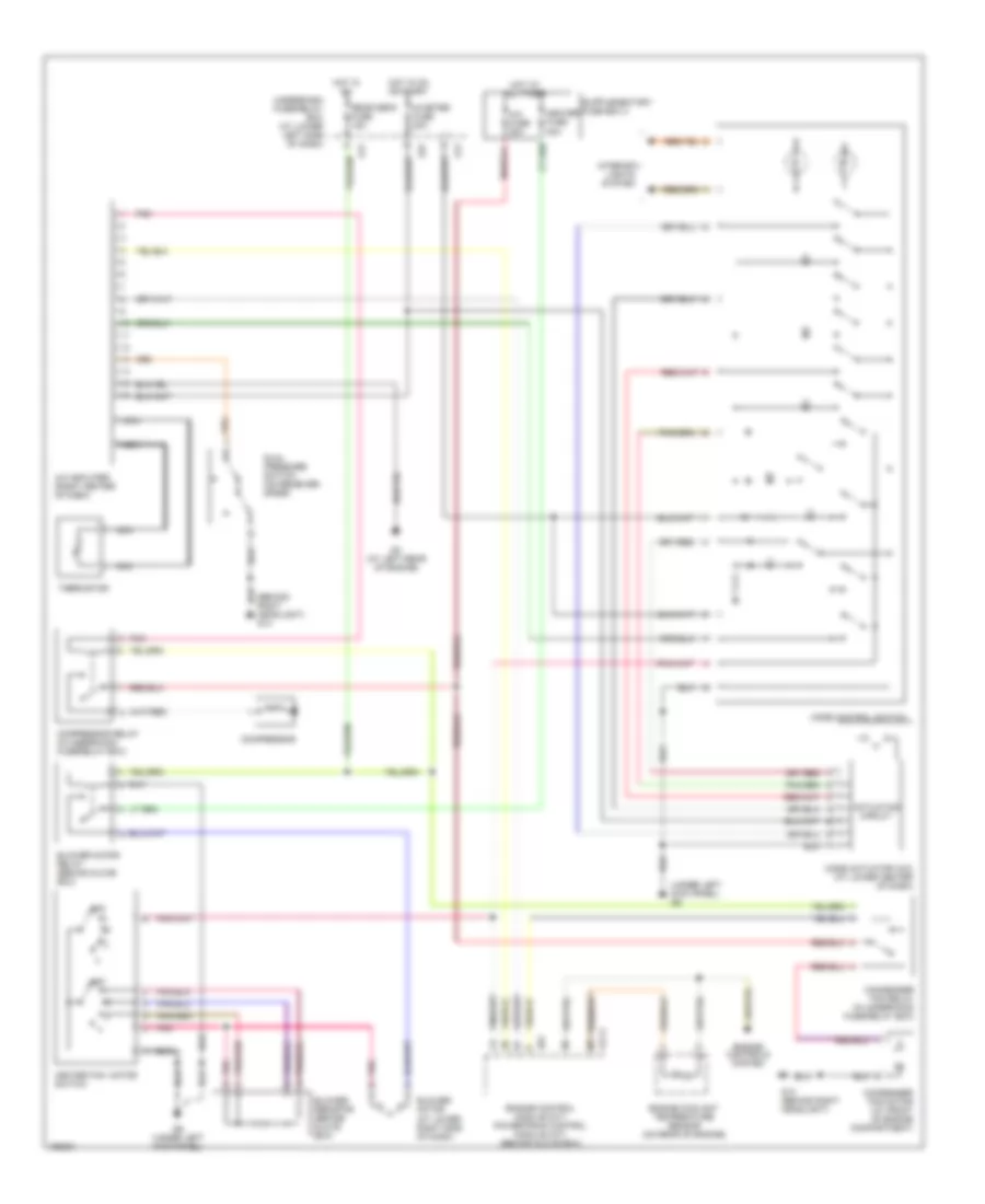
AIR CONDITIONING
Manual A/C Wiring Diagram for Suzuki Vitara 2004
 https://portal-diagnostov.com/license.html
Automotive Electricians Portal FZCO
Automotive Electricians Portal FZCO
https://portal-diagnostov.com/license.html
https://portal-diagnostov.com/license.html
Automotive Electricians Portal FZCO
Automotive Electricians Portal FZCO
List of elements for Manual A/C Wiring Diagram for Suzuki Vitara 2004:
- (behind right headlight) g14
- (under left kick panel) g9
- A/c amplifier (right center of dash)
- A/c fuse 25a
- Actuating circuit
- Blower motor (at lower right side of dash)
- Blower motor relay (behind glove box)
- Blower resistor (behind glove box)
- C51-3
- Compressor
- Compressor relay (in underhood fuse/relay box)
- Condenser fan motor (at front of engine compartment)
- Condenser fan relay (in underhood fuse/relay box)
- Dual pressure switch (on receiver- drier)
- E27
- E61
- Engine control module (m/t) powertrain control module (a/t) (behind glove box)
- Engine controls system
- Engine coolant temperature sensor (on rear of engine)
- G14 (behind right headlight)
- G17
- G3 (at left rear of engine)
- G9 (under left kick panel)
- Heater fan motor switch
- Heater fuse 30a
- Hot at all times
- Hot in on
- Hot in on or start
- Ig meter fuse 20a
- Interior lights system
- Mode actuator (a/c) (at lower center of dash)
- Mode control switch
- Nca
- Off
- Pnk
- Rear defg fuse 15a
- Thermistor
- Underdash fuse/relay box (at lower left side of dash)